Note: Descriptions are shown in the official language in which they were submitted.
;~139~37
....
The present invention relates generally to deYices for
positioning items, such as anchor bolts and reinforcement
bars, within a form for their subsequent embedment within
concrete. ~ore speci~ically, the present invention relates to
devices which rigidly secure such items to a single ~or~
board.
In the formation of building foundations and the like,
builders typically embed various items within concrete
portions of the foundation. The foundations are formed by
pouring wet concrete into an interior portion of a form, and
the embedded items are either positioned within the form prior
to ~he pouring of the concrete or poked into the concr~te
before tne concrete hardens~ Steel reinforcing bars trebar)
are usually embedded to strengthen the resulting foundation.
In addition, anchor bolts, also known as "~-bolts," are often
partially embedded in the foundation. Exposed portions of
anchor bolts serve to attach a building or other structure to
the foundation.
Many foundations utilize a relatively narrow form. In
other words, the distance between non-collinear for~ boards is
relatively short. Due to this short distance, numerous
devices have been developed which rest upon opposing or
perpendicular form boards and which suspend embedable items
from such devices between the form boards. Such devices are
believed to wor~ acceptably well in applications where these
form boards are positioned close together.
However, in the southwestern regions of the United States
and in other locations, common building practices call for
monolithic slab foundations. Monoli~hic slab foundationS
represent vast, contiguous concrete floors which underlie all,
,
.
2 ~:0~ 37
or at least major portions, of their buildings. The
monolithic slab foundations are formed on~site using a ~orm in
which the distance between non-collinear form boards is
relatively great. For a typical single family house, this
distance usually spans the entire length or width of the
house. Thus, for monolithic slabs, the use of conventional
devices which suspend e~bedable items between form boards is
totally impractical.
As a consequence, make-shift techniques are often devised
to embed items in monolithic slab foundations.
Conventionally, rebar is positioned by attaching the rebar to
wooden staXes or other convenient items prior to the pouring
of concrete. As a result, this positioning is typically a
time consuming, costly, and yet imprecise task in the
construction of a foundation.
Make-shift techniques and devices have also been devised
for suspending anchor bolts in a cantilever fashion from a
single form board. However, such make-shift techniques and
devices have proven unsatisfactory. Typically, conventional
make-shift suspending devices are either too flimsy or attach
to the for~ boa~d too unsubstantially to adequately hold an
anchor bolt. Consequently, anchor bolts tend to sag or
otherwise come out of alignment under their own weight, when
jostled by normal construction activities, or when bumped by
concrete buffing machines. As a result, such make-shift
devices tend not to be used at all.
Rather, anchor bolts are typically stabbed into wet
concrete soon after the concrete has been poured. The
stabbing of anchor bolts into wet concrete is particularly
undesirable for several reasons. For example, the anchor
bolts cannot be positively tied into the rebar structure of
the foundation. Failure to tie anchor bolts into a rebar
structure severely diminishes the building's overall strength
and ability to withstand earthguakes. Moreover, inspec~ion of
3 ~ 3~
embedded portions of anchor bolts is impossible after concrete
has been poured.
In addition, the stabbing of anchor bolts into wet
concrete is a slow, tedious, and generally unsatisfactory
process. Precise measurements are required to correctly
position the anchor bolts. For example, the height of the
anchor bolts above the concrete, the angle of the anchor bolts
projecting out from concrete, and the positioning of the
anchor bolts within the form must all be set for each anchor
bolt. Then, timing considerations complicate the process. If
the concrete is too wet when the anchor bolt is stabbed, the
', anchor bolt tends to sag or fall over. If the concrete is too
hard when the anchor bolt is stabbed, embedding the anchor
bolt and adequately molding the concrete around the anchor
bolt become difficult. As a result of the numerous problems
associated with stabbing anchor bolts into wet concrete,
frequent rework is required. Slnce this rewGrk doesn't occur
until after the concrete has hardened, it is time consuming,
difficult and expensive.
Accordingly, it is an advantage of the present invention
that an improved apparatus for posi~ioning ite~s for
subsequent embedment in concrete is provided.
Another advantage of the present invention is that a
cantilever apparatus is provided so that items may be
positioned relative to a single form board. ~hus, the present
invention is useful in the construction of monolithic slab
foundations, as well as other concrete structures.
Yet another advantage is that the present invention
represents a positioning apparatus which rigidly holds items,
; e.g. anchor bolts. Thus, such items tend to remain in
place throughout the formation of a ~oundation.
Still another advantage is that the present invention is
capable o~ rigidly supporting su~stantial weight in addition
- .:
. , .
4 ~ 3~
to an anchor bolt. Thus, rebar may be directly tied to and
supported by the present invention.
Another advantage is that the present invention permits
the tying of rebar to an anchor bolt in numerous diverse
configurations.
The terms "vertical" and "horizontal" are used herein as
relative terms to describe items whose orientations are
generally similar to or are substantially different from one
another. Those skilled in the art will recognize that only
general orientations and not precise orientations relative to
the direction of force exerted by gravity are implied. In
other words, as used herein ~vertical" and "horizontal" refer
to directions which may differ considerably from precisely
vertical and precisely horizontal orientations, respectively.
While the terms 'Ivertical~ and "horizontal" apply to
orientations of items during normal usage of the present
invention, those skilled in the art will further recognize
that all such items may, in other circumstances, be physically
orien~ed so that "vertical" items extend precisely
~0 "horizontal" and vice-versa.
The above and other advantages of the present invention
are carried out in one form by an apparatus which rigidly
positions an anchor bolt alongside an interior vertical
surface of a form board. The anchor bolt may thereafter be
embedded in concrete. The apparatus includes a member which
extends in a generally vertical direction when sPcured to an
exterior vertical surface of the form board. In addition, the
apparatus includes a member which extends in a generally
horizontal dixection when the appara~us is secured to the form
board. The horizontally extending member rigidly attaches to
the vertically extending member at substantially a
perpendicular angle. Moreover, the horizontally extending
member is configured to rest upon a top horizontal surface of
the form board. The apparatus also includes a device which
: '
,
2~9~317
couples to the horizontally extending member to releasably
hold the anchor bolt.
In the accompanying drawings: .
FIGURE 1 shows a perspective Vi2W of a holding device
constructed in accordance with the teaching of the present
invention and attached to a form board;
FIGURE 2 shows a cross-sectional side view of a ~irst
embodiment of the holding device of the present invention;
FIGURE 3 shows an exploded, perspective view of a first
embodiment of the holding device of the present invention;
FIGURE 4 shows an exploded, perspective view of a second
embodiment of the holding device of the present invention;
FIGURE 5 shows a cross-sectional side view of the second
embodiment of the holding device of the present invention;
FIGURE 6 shows the present invention operated to position
anchor bolts for embedment in concrete and attachment to a
column;
FIGURE 7 shows a cross-sectional side view of the present
invention taken about line 1--7 of FIGURE 6;
: FIGURE 8 shows the holding device of the present
invention installed on a one-by form board;
FIGURE 9 shows the holding device of the present
invention supporting a curtain wall of rebar;
FIGURE 10 shows a perspective view of a cradle portion of
the present invention supporting a rebar in a first
orientation;
:: FIGURE 11 shows a side view of the cradle portion of the
~ present invention supporting a rebar in the ~rst orientation;
,
,, ,
Z~3~3~3~
FIGURE 12 shows a perspective view of the cradle portion
of the present invention supporting a rebar in a second
orientation;
FIGURE 13 shows a side view of the cradle portion of the
present invention supporting a rebar in the second
orientation; and
FIGURE 14 shows a cross-sectional side view taken about
line 1~--14 of FIGURE 12.
In accordance with the teaching of the present invention,
FIGURES 1-3 show a first embodiment of a holding device 10,
which is used to position items for embedment in concrete 12.
For the purposes of the present invention, concrete 12 may,
but need not necessarily, represent a monolithlc slab
foundation. Holding device 10 positions a conventional anchor
bolt 14 relative to a conventional 'itwo-by" (ie. 2 X 6, 2 X 8,
X 10, etc.) form board 16. As is conventional, form board
16 serves as one stop in a form 18 into which concrete 12 is
poured while in a wet state. When concrete 12 hardens, form
18, including form board 16, is removed and concrete 12
retains the shape (not shown) defined by form 18.
With specific reference to FIGURE 3, holding device 10
includes a wrench 20, a wrench receiver 22, a thumb-screw 24,
and a steel strap 26. In the preferred embodiments, strap 26
is approximately 3/16 inch thic~ steel that is approximately
3/4 inch wide. Strap 26 is bent into a fastener 28, a spacer
30, and 2n elevator 32. Fastener 26 extends to a corner 34.
At corner 3~, fastener 26 joins spacer 30, which extends to a
`! 30 corner 36. At corner 36, spacer 30 joins elevator 32.
Corners 34 and 36 ma~e approximately 90- angles in strap 26.
Thus, fastener 28 extends vertically, spacer 30 extends
horizontally, and elevator 32 extends vertically. In the
preferred e~bodiments, ~astener 28 extends approximately four
inches, spacer 30 extends approximately 7/8 inch inside-to-
~36~3~
inside, and elevator 32 extends approximately 5/8 of an inch
from its end to the bottom of spacer 30.
In the preferred embodiments, wrench receiver 22 is
formed from hollow, square steel channel, approximately 3/4
inch on a side in cross section and approximately khree inches
long. A top surface of wrench receiver 22 includes a threaded
hole 38 into which thumb screw 24 is screwed. Hole 38 may be
directly taped in wrench receiver 22 or include a threaded nut
welded to wrench receiver 22. Wrench receiver 2~ is rigidly
mounted, preferably by welding, upon spacer 30 of strap 26.
Accordingly, wrench receiver 22 extends horizontally. In
addition, wrench receiver 22 is positioned relative to strap
26 so that one end of wrench receiver 22 is generally flush
with elevator 32. Thus, a little less than two inches of
wrench receiver 22 does not directly overlie any portion of
strap 26.
In the preferred embodiments, wrench 20 is formed from a
nut 40 and a hollow, square steel channel 42 approximately six
inches long. In cross section, channel 42 is smaller on a
side than the interior of wrench receiver 22. Thus, channel
42 slidably fits within the interior of wrench receiver 22.
For example, channel 42 may be 5/8 or 1/2 inch channel. Nut
40 is preferably a threaded steel nut which is welded to an
end of channel 42 so that a hole 44 in nut 40 may extend
vertically through nut 40. In addition, a top side of wrench
20 includes first and second notches 46a and 46b.
In attaching holding device 10 to form board 16, a
desired position is first identified on form board 16 for the
attachment of holding device 10. The measuring required in
~; 30 this identification is a relatively simple task because a
position for holding device 10 must be determined in only the
one dimension for which form board 16 principally extends. In
addition, a single operation may measure positions for
multiple holding devices 10 along form board 16.
~3~7
.
Consequently, positions for several holding devices 10 mzy bedetermined quickly.~ olding device lO is positioned at the indicated location
and, as shown in FIGURES 1-3, oriented so that Lastener 28
lies alongside an exterior vertical surface 4~ of form board
16, and elevator 32 rests directly on a top horizontal sur~ace
50 of form board 16. Fastener 28 includes centrally located
holes 52a and 52b, which serve in attaching holding device 10
to form board 16. Preferably, double-headed nails 54a and 54b
are driven through holes 52a-52b, respectively, to securely
fasten fastener 28 to form board 16 at the indicated position
on exterior vertical surface 48. Double-headed nails ease
nail removal after concrete 12 has hardened.
As is conventional, anchor bolt 1~ includes threads 56.
: 15 Nut 40 is chosen so that it is compatibly threaded ~ith
threads 56. Thus, anchor bolt 14 is threaded into nut 40 a
desired distance and a finger portion 58 of anchor bolt 14
pointed a desired direction. In addition, wrench 20 is
inserted in wrench receiver 22. Specifically, wrench 20 is
inserted in wrench receiver 22 so that anchor bolt 14 extends
in a vertical orientation and is spaced inwardly, relative to
form 18, and apart from an interior vertical surface 60 o~
form board 16.
Moreover, wrench 20 is inserted in wrench receiver 22 so
that one of notches 46a-46b aligns with a predetermined point,
e.g. interior vertical surface 60 of form 16. Notches 46a-
46b are positioned on wrench 20 so that when they are so
aligned, the center of nut 40 and of anchor bol~ 1~ are spaced
a predetermined distance away fro~ interior vertical surface
`30 60. In the preferred embodlment, these predetermined
distances indicated by notches 46a and 46b are approximately
1-3/4 and 2-3/4 inches, respectively, from surface 60. Notch
46a aligns anchor bolt 14 with the center of a conventional
building's 2 X 4 mud sill, and notch 46b aligns anchor bolt 14
with the center of a conventional building's 2 X 6 mud sill.
.
~39~37
g
Once wrench 20 has been ins~rted so that the desired one o~
notches 46a-46b aligns with the desired point, thumb screw 24
is tightened against wrench 20 to lock wrench 20 in place
within wrench receiver 22.
When all holding devices 10 required by a foundation have
been positioned as described above, inspections may take place
and then concrete 12 poured. After concrete 12 hardens, thumb
screws 24 are loosened~ nails 54 are removed, and wrenches 20
are unscrewed from anchor bolts 1~. In addition to
extricating wrench 20 from anchor bolt 14, the unscrewing of
wrench 20 cleans concrete 12 from threads 56 of anchor bolt
14.
FIGURES 4-5 show a second preferred embodiment of holding
device 10. As discussed above, in the first embodiment
illustrated by FIGURES 1-3, wrench 20 extends for
approximately six inches from nut 40. Accordingly, in order
to unscrew wrench 20 from anchor bolt 14 after concrete 12
(see FIGURE 2) hardens, clear space around anchor bolt 14 with
a minimum radius of six inches must exist. However, anchor
bolt 14 may occasionally be located near an obstruction, such
as a vertically running water or gas pipe, which would impede
the removal of wrench 20 from anchor bolt 14. The second
embodiment illustrated by FIGURES 4 5 addresses the problem of
- nearby obstructions.
As shown in FIGURES 4-5, wrench receiver 22, thumb screw
24, and strap 26 are all configured substantially as discussed
above in connection with FIGURES 1-3. However, a wrench 20l
of this second embodiment differs from wrench 20 of the first
embodiment. Specifically, a nut 40' attaches to an end of a
hollow, square steel channel 41', which is approximately 1
inch long. Preferably, channel 41' is approximately 1/2 inch
on a side in cross section. Another hollow, square steel
channel 42' is approxinately six inches long. Channel 42',
which is preferably around 5/8 inch on a side in cross
section, slidably mates with wrench receiver 22 as discussed
~03~3~
above in connection with channel 42. Channel 42' includes a
threaded hole 62 to which a thumb screw ~4 mates.
Additionally, channel 42' includes notches 46a-46b, as
discussed above.
Channel 41' mates with channel 42' in a manner similar to
the way channel 42' mates with wrench receiver 22.
Specifically, channel 41' slidably mates with channel 42' and
is locked in place by thumb screw 64. This second embodiment
is utilized substantially as discussed above in connection
with the first embodiment. However, after concrete 12 (see
FIGURE 2) has hardened, channel 42' may be separated from
channel 41~ by loosening thumb screw 64. since channel 41' is
only around one inch long, nut 40' and channel 41' may be
unscrewed from anchor bolt 14 when obstructions are nearby.
While the above discussion relates to the positioning of
items relative to a single form board 16, the present
invention is n~t limited to such use and may be adapted for
use in connection with suspending items from ~eams supported
by two form boards 16 located on opposing sides of the items,
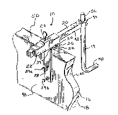
as shown in FIGURE 6. FIGURE 6 shows a plate 68 having four
anchor bolts 14 attached thereto for embedment in concrete
(not shown) and subsequent attachment to a column (not shown).
Plate 68 is suspended from beams 70 and 72. Beam 70 extends
across the entire width of form 18 from a form board 16a to a
form board 16b, which opposes form board 16a. Likewise, beam
72 extends across the entire length of form 18 from a form
board 16c to a form board 16d, which opposes form board 16c.
Beams 70-72 mate with wrench receivers 22 in the manner
discussed above in connection with FIGU~ES 1-5 for wrench 20.
Stop pins 74 retain plate 68 centrally positioned on one of
beams 70-72 while permitting sliding movement with the other
of beams 70-72. Thus, plate 68 may be precisely positioned at
a desired location within form 18 by adjusting beams 70-72 and
locking thumb screws 24.
.
,
.
9~37
11
In addition, beam 70 resides below beam 72. The diverse
heights achieved by beams 70-72 result from ori~nting holding
devices lOa and lOh, which collectively retain beam 70,
differently from holding devices lOc and lOd, which
collectively retain beam 72. As shown in FIGURE 6, elevators
32 of holding devices lOc-lOd are placed on top surfaces 50 of
form boards 16c-16d, respectively, in the manner discussed
above in connection with FIGURES 1-5. On the other hand,
elevators 32 of holding devices lOa-lOb are not used in
connection with form boards 16a-16b. Rather, holding devices
lOa-lOb are turned around so that their wrench receivers 22
directly rest on top surfaces 50 of form boards 16a-16b,
respectively. F~GURE 7 illus~rates this orientation of
holding devices lOa-lOb in greater detail. Thus, beam 70 is
spaced below beam 72 by the length of elevators 32. The same
alternate orientation relative to form boards 16 may be used
to achieve greater flexibility in vertically positioning
anchor bolts 14 (see FIGURES 1-5) relative to concrete 12 (see
FIGURE 2).
FIGURE 8 shows yet another use of holding device 10 in
connection with a form board 16e. Form board 16e represents
conventional "one-by" lumber (ie. 1 X 6, 1 X 8, 1 X 10, etc.),
which is typically around 7/8 inch thick. In this
orientation, elevator 32 extends vertically downward alongside
interior vertical surface 60 of form board 16e, and spacer 30
rests directly on top surface 50 of form board 16e.
Accordingly, holding device 10 rigidly and securely attaches
to one-by form board 16e due ~o the cooperative dimensioning
between spacer 30, elevator 3~, and the thickness of form
board 16e.
The above-discussed embodiments of holding device 10
operate to rigidly hold anchor bolt 14 in position relative to
form board 16. This rigidness or security occurs, at least in
part, from the attachment of fastener 28 to exterior vertical
surface 48 of form board 16, to the resting of wrench receiver
3~3~37
22 on top surface 50 of Porm board 16, either directly or
through elevator 32, and the metal construction o~ the
components of holding device 10. As shown in FIGU~E 9, this
rigidity in holding anchor bolt 14 permits anchor bolt 14 to
support additional items, such as reinforcing steel bars
(rebar~ 76. Specifically, an entire curtain wall of rebar 76
may be positively tied or wired to anchor bolt 14 and
supported by anchor bolt 14 within form 18 without causing
anchor bolt 1~ or rebar 76 to sag or otherwise move out of
position.
However, conventional foundation construction practices
occasionally specify that rebar 76 should be positioned
further inward within form 18 from anchor bolt 14.
Accordingly, a cradle 78 constructed in accordance with the
teachings of the present invention, as illustrated in FIGURES
10-14, may serve to conveniently tie rebar 76 and anchor bolt
14 together while simultaneously spacing rebar 76 away from
anchor bolt 14. ~olding device 10 supports cradle 78 along
with all rebar 76 tied thereto.
Cradle 78 represents a specifically configured, stamped
piece of metal strapping. Preferably, cradle 78 is six-eight
inches in length and bent so that a spacer section 80 resides
at one end of cradle 78 and a finger section 82 resides at the
other. A bolt hole 84 extends vertically through the
thickness of spacer 80 near an end of cradle 78, and a rebar
hole 86 extends vertically through the central portion of
spacer 80. Hole 84 is generally circular ~hile hole 86 is
elongated. In addition, cradle 78 is dimpled throughout most
of its length. Accordingly, cradle 78 exhibits a concave
shape, with an opening pointing up. This concave shape
enhances the strength of cradle 78 and ~orms a spoon section
88 in the end of cradle 78 provided by finger 82. Spoon
section 88 conforms to the circular cross-sectional shape of
conventional rebar, as discussed below in connection with
FIGURES 12-14.
.
~3~ 7
Bolt hole 84 in cradle 78 is dimensioned in cooperation
with anchor bolt 1~. In particular hole 84 has a diameter
slightly larger than the diameter of anchor bolt 14. Thus,
anchor bolt 14 may be inserted through hole 8~ and cradle 78
may freely slide up and down on anchor bolt 14 when anchor
bolt 14 is installed in hole 84. On the other hand, the
diameter of hole 84 is not significantly larger than the
diametex of anchor bolt 14. Thus, unless spacer section 80 is
positioned generally perpendicular to anchor bolt 14, a wall
90, which surrounds hole 84, of cradle 78 binds against anchor
bolt I4. This binding prevents movement of cradle 78 on
anchor bolt 14 and occurs when spacer 80 is positioned at an
angle ~ relative to anchor bolt 14.
Accordingly, cradle 78 may be installed on an anchor bolt
14 and raised or lowered so that, when it is placed at angle
relative to anchor bolt 14, it resides at a desired position.
The force exerted by gravity on cradle 78 serves to maintain
angle ~. Consequently, cradle 78 remains at the selected
location re~lative to anchor bolt 14.
ZO As shown in FIGURES 10 and 11, this desired position
allows rebar 76 to be positioned at a desired vertical
location. When spacer 80 exhibits angle ~, it is angled
slightly downward. The bend which forms an intersection 92
between spacer 80 and finger 82 defines an anyle B which
causes finger 82 to projec~ slightly upward. In the preferred
embodiments angle B is around 90-. Thus, when rebar 76 is
oriented generally parallel ~o form board 16 ~see FIGURE 9),
the force exerted on rebar 76 by gravity urges rebar 76 to
remain at intersection 92. Moreover, the additional weight
added to cradle 78 by rebar 76 serves to increase binding
forGes between anchor bolt 14 and wall 90 so that cradle 78
remains clamped in place on anchor bolt 14.
FIGURES 12-14 illustrate an alternate use of cradle 78 in
positioning and tying rebar 76 to anchor bolt 14. Rebar hole
86 is suf~iciently large so that rebar 76 easily ~its therein,
,
:
~3~3~7
14
including any distortions of rebar 76 caused by bending.
Thus, FIGU~ES 12~14 show various views of rebar 76 extending
through rebar hole 86 toward anchor bolt 14 and form board 16
(see FIGURES 1,~, and 9). Typically, in this alternate use,
rebar 76 is bent downwards, as shown in FIGURES 12-13 or
sideways lnot shown) in the vicinity of anchor bolt 14~ Of
course, additional rebar 76 may be tied into the rebar 76
positioned using cradle 7~.
In addition, rebar hole 86 resides at a location
determined in cooperation with angle ~, angle B, the length of
finger 82, and the diameter of rebar 76. Specifically, when
cradle 78 exhibits angle ~ relative to anchor bolt 14, spoon
88 resides below an upper wall 94 of hole 86 by a distance
substantially equivalent to the diameter of rebar 76. Upper
wall 94 is the wall of hole 86 which resides nearest bolt hole
84. Those skilled in the art may properly position spoon 88
by controlling angle ~ in cooperation with the length of
finger 82 in accordance with well known trigonometric
principles. As a result, when rebar 76 is installed through
hole 86 and rests in spoon 88, it is substantially level and
perpendicular to anchor bolt 14.
The concave shape of cradle 78 in the vicinity of spoon
88 conforms to the shape of rebar 76 and causes rebar 76 to
remain stably positioned so that minor bumps and other
construction jostles do not dislodge rebar 76 from cradle 78.
In addition, the weight of rebar 76 extending away from anchor
bolt 14 and cradle 78 firmly positions rebar 76 against upper
wall 94 and firmly clamps cradle wall 90 to anchor bolt 14.
In summary, the present invention provides an improved
apparatus for positioning items so that they may subsequently
be embedded in concrete. The present invention includes a
cantilever holding device which positions items relative to a
single form board. Thus, the present invention is useful in
the construction of monolithic slab foundations. The holding
device is configured for quicX and easy positioning of anchor
I ~ID39~3'7
bolts in a variety of different applications~ Moreover, the
present invention rigidly holds items so that ~he weight of
I anchor bolts and rebar and the no~mal jostling which occurs
during construction do not significantly alter positioning.
Furthermore, the present invention includes a cradle which
permits spacing and tying of rebar relative to an anchor bolt.
The cradle is configured for convenient use and flexibility in
adapting it to rebar structures. As a result of the present
invention, foundation strength improves due to the tying of
anchor bolts into rebar structures, construction time
decreases due to ease and convenience in using the present
j invention, accurate and meaningful inspections may take place
prior to the pouring of concrete, and rework time is reduced.
The present invention has been described above with
reference to preferred embodiments. However, those skilled in
the art will recognize that changes and modifications may be
made in ~hese preferred embodiments without departing fro~ the
scope of the present invention. For example, while the above
discussion mentions the use of metal components, nothing
prevents suitable plastic materials from being adapted for one
or more o~ the components included in the present invention.
In addition, the precise dimensions mentioned above may be
substantially changed in order to adapt the present invention
to different applications.
: