Language selection

Search

Patent 2039664 Summary

Third-party information liability

Some of the information on this Web page has been provided by external sources. The Government of Canada is not responsible for the accuracy, reliability or currency of the information supplied by external sources. Users wishing to rely upon this information should consult directly with the source of the information. Content provided by external sources is not subject to official languages, privacy and accessibility requirements.

Claims and Abstract availability

Any discrepancies in the text and image of the Claims and Abstract are due to differing posting times. Text of the Claims and Abstract are posted:

  • At the time the application is open to public inspection;
  • At the time of issue of the patent (grant).
(12) Patent: (11) CA 2039664
(54) English Title: BARRIER PLUG FOR A BORE
(54) French Title: CLAPET OBTURATEUR POUR SONDAGE
Status: Expired and beyond the Period of Reversal
Bibliographic Data
(51) International Patent Classification (IPC):
  • E02D 5/74 (2006.01)
  • E04B 1/41 (2006.01)
  • E21D 20/02 (2006.01)
(72) Inventors :
  • GRBAVAC, ROGER (United States of America)
  • MCCARTNEY, CLIFFORD A. (United States of America)
(73) Owners :
  • INGERSOLL-RAND COMPANY
(71) Applicants :
  • INGERSOLL-RAND COMPANY (United States of America)
(74) Agent: SWABEY OGILVY RENAULT
(74) Associate agent:
(45) Issued: 1995-12-12
(22) Filed Date: 1991-04-03
(41) Open to Public Inspection: 1991-10-20
Examination requested: 1991-04-03
Availability of licence: N/A
Dedicated to the Public: N/A
(25) Language of filing: English

Patent Cooperation Treaty (PCT): No

(30) Application Priority Data:
Application No. Country/Territory Date
510,925 (United States of America) 1990-04-19

Abstracts

English Abstract


A barrier for use with a rod extending into a bore
having a cross sectional dimension, formed in a structure.
The barrier is located on one side of a fluid supply in the
bore. The barrier includes a sealing portion adjacent the
fluid supply, the sealing portion has a flexible flange in
sealing contact with the bore. A tube is connected to the
sealing portion and has a rod passageway formed there
through. A diameter of the tubular portion is smaller than
the cross sectional dimension prior to insertion of the rod,
and expands to conform to the cross sectional dimension in
response to insertion of the rod. A rupture portion is
connected to the tubular portion, and seals the rod
passageway to limit a passage of fluid therethrough prior to
insertion of the rod. The rupture portion is adapted to
rupture in response to penetration by the rod. The barrier
may be used in conjunction with a dynamic earth anchor, to
prevent passage of the grout to between the anchor and the
bore.


Claims

Note: Claims are shown in the official language in which they were submitted.

The embodiments of the invention in which an
exclusive property or privilege is claimed are
defined as follows:-
1. A barrier means for use in combination with a
rod extending into a bore having a cross-sectional
dimension, formed in a terrestrial structure, the
barrier being located on one side of a fluid in the
bore, the barrier comprising:
a tubular portion connected to a sealing
portion, the tubular portion having a rod passageway
formed therethrough, a diameter of the tubular
portion being smaller than the cross-sectional
dimension prior to insertion of the rod, and
expanding to conform to the cross-sectional
dimension in response to insertion of the rod, the
rod passageway forming a seal with the rod after
insertion of the rod; and
rupture means being formed in the tubular
portion for sealing the rod passageway to limit a
passage of fluid therethrough prior to insertion of
the rod, and adapted to rupture in response to
penetration by the rod.
2. The barrier as defined in claim 1, further
comprising:
the sealing portion adjacent the fluid has a
flexible flange in sealing contact with the bore.
3. The barrier as defined in claim 1, wherein
the tubular portion comprises:
a sleeve means for connecting the rod to a
portion of the bore.
4. A terrestrial restraint to be inserted into a
bore having a bore wall formed in a terrestrial
structure comprising:

a rod having a first axial segment and a
second axial segment, the first axial segment being
axially spaced from the second axial segment;
sleeve means engaging the first axial
segment, for securing the first axial segment to a
first axial portion of the bore;
hardenable fluid grout means engaging the
second axial segment for securing the second axial
segment to a second axial portion of the bore;
barrier means inter-spaced between the sleeve
means and the fluid grout means for restricting
grout passage from the second axial segment to the
first axial segment of the bore, the passage of
grout being restricted both prior to and after
insertion of the rod into the bore.
5. The restraint as described in claim 4,
wherein the barrier means comprises:
a flange mounted circumferentially of said
barrier means, an outer periphery of which engages
the bore wall.
6. The restraint as described in claim 4,
wherein the barrier means includes a body portion
which, when inserted into the bore, is axially
aligned therewith.
7. The restraint as described in claim 6,
wherein the cross-section of the body portion is a
first dimension prior to said rod insertion and a
second dimension after said rod insertion, said
first dimension being less than a diameter of the
bore wall, and the second dimension being greater or
equal to the diameter of the bore wall.

8. The restraint as described in claim 6,
wherein the body portion includes an aperture having
an aperture wall formed therein which, after the rod
insertion, forms a seal between the rod and the
aperture wall.
9. The restraint as described in claim 6,
further comprising:
an aperture formed in the body portion; and
rupture means, proximally located to the
aperture, for preventing grout passage through the
aperture prior to said rod insertion.
10. The restraint as described in claim 9,
wherein the rupture means comprises:
a cap portion which is mounted on a face of
the body portion adjacent the first axial portion.
11. The restraint as described in claim 9,
wherein the rupture means comprises:
a diaphragm disposed within the aperture.
12. The restraint as described in claim 4,
wherein the grout is a resin-hardener mixture.
13. The restraint as described in claim 4,
wherein the grout is a cement.
14. A barrier plug for insertion into a bore
formed in a terrestrial structure for restricting
passage of a grout from a first portion to a second
axial separated portion of the bore, the barrier
plug comprising:
a body portion having an axially extending
aperture located within the body portion permitting
insertion of a rod therethrough, said aperture being

formed by an aperture wall, after said rod
insertion, forms a seal between the aperture wall
and the rod;
rupture means for preventing grout passage
through the aperture prior to said rod insertion,
and adapted to be ruptured by the rod insertion; and
seal means for preventing grout passage
between the body portion and the bore both prior to
and after the rod insertion.
15. The plug as described in claim 14, wherein
the seal means comprises:
a flange mounted circumferentially of the
body portion, an outer periphery of which engages a
bore wall which forms the bore.
16. The plug as described in claim 14, wherein a
cross-section of the body portion is a first
dimension prior to said rod insertion and a second
dimension after said rod insertion, said first
dimension being less than a diameter of the bore
wall, the second dimension being greater or equal to
the diameter of the bore wall.
17. The plug as described in claim 14, wherein
the rupture means comprises:
a cap portion which is mounted on a face of
the body portion adjacent the first axial portion.
18. The plug as described in claim 14, wherein
the rupture means comprises:
a diaphragm disposed within the aperture.
19. The restraint as described in claim 14,
wherein the grout is a resin-hardener mixture.

20. The restraint as described in claim 14,
wherein the grout is a cement.

Description

Note: Descriptions are shown in the official language in which they were submitted.


203~664
Docket No. 1012-IR-RD
BARRIER PLUG FOR A BORE
BACKGROUND OF THE INVENTION
This invention relates generally to barrier members, and
more particularly to a barrier member to prevent the passage
of fluid from a first portion of a bore formed in a
structure to a second portion, located on the other side of
the barrier member. This invention is especially applicable
to the restriction of grout to a specific portion of the
bore.
In one present system, grout has been used in
conjunction with a sleeve to maintain a dynamic rock anchor
in a bore. This grout often seeps between the sleeve and
the bore. This grout can act as lubrication, permitting the
sleeve to be displaced when a rod is inserted into the
sleeve.
Also, when the rod is inserted behind the grout, the rod
often can force the grout through a hole in the sleeve. If
the depth of the bore is limited, then the grout will
collect in the upper portion of the bore. This grout will
develop hydraulic lock and will prevent the full extension
of the rod into the bore.
-1- ,~

2~39~6~
Docket No. 1012-IR-RD
The foregoing illustrates limitations known to exist in
present dynamic rock anchors. Thus, it is apparent that it
would be advantageous to provide an alternative directed to
overcoming one or more of the limitations set forth above.
Accordingly, a suitable alternative is provided including
features more fully disclosed hereinafter.
SUMMARY OF THE INVENTION
In one aspect of the present invention, this is
accomplished by providing a barrier for use with a rod
extending into a bore having a cross sectional dimension,
formed in a structure The barrier is located on one side
of the fluid in the bore.
A tubular portion is connected to the sealing portion
and has a rod passageway formed therethrough. A diameter of
the tubular portion is smaller than the cross sectional
dimension prior to insertion of the rod, and expands to
conform to the cross sectional dimension in response to
insertion of the rod. A rupture portion is connected to the
tu~ular portion, and seals the rod passageway to limit the
passage of fluid therethrough prior to insertion of the
rod. The rupture portion is adapted to rupture in response
to penetration by the rod.
--2--

2039664
According to a further broad aspect of the
present invention, there is provided a barrier means
for use in combination with a rod extending into a
bore having a cross-sectional dimension, formed in a
terrestrial structure, the barrier being located on
one side of a fluid in the bore. The barrier
comprises a tubular portion connected to a sealing
portion. The tubular portion has a rod passageway
formed therethrough. A diameter of the tubular
portion is smaller than the cross-sectional
dimension prior to insertion of the rod, and
expanding to conform to the cross-sectional
dimension in response to insertion of the rod. The
rod passageway forms a seal with the rod after
insertion of the rod. Rupture means is formed in
the tubular portion for sealing the rod passageway
to limit a passage of fluid therethrough prior to
insertion of the rod, and adapted to rupture in
response to penetration by the rod.
According to a still further broad aspect of
the present invention, there is provided a
terrestrial restraint to be inserted into a bore
having a bore wall formed in a terrestrial
structure. The terrestrial restraint comprises a
rod having a first axial segment and a second axial
segment, with the first axial segment being axially
spaced from the second axial segment. Sleeve means
engages the first axial segment for securing the
first axial segment to a first axial portion of the
bore. Hardenable fluid grout means engages the
second axial segment for securing the second axial
segment to a second axial portion of the bore.
Barrier means is inter-spaced between the sleeve
means and the fluid grout means for restricting
grout passage from the second axial segment to the
~'

2039664
first axial segment of the bore. The passage of
grout is restricted both prior to and after
insertion of the rod into the bore.
According to a still further broad aspect of
the present invention, there is provided a barrier
plug for insertion into a bore formed in a
terrestrial structure for restricting passage of a
grout from a first portion to a second axial
separated portion of the bore. The barrier plug
comprises a body portion having an axially extending
aperture located within the body portion and
permitting insertion of a rod therethrough, the
aperture being formed by an aperture wall, after the
rod insertion, forms a seal between the aperture
wall and the rod. Rupture means is provided for
preventing grout passage through the aperture prior
to the rod insertion, and adapted to be ruptured by
the rod insertion. Seal means is also provided for
preventing grout passage between the body portion
and the bore, both prior to and after the rod
insertion.
- 2b -
,~
-

20~9664
Docket No. 1012-IR-RD
The foregoing and other aspects will become apparent from
the following detailed description of the invention when
considered in conjunction with the accompanying drawing
figures.
BRIEF DESCRIPTION OF THE DRAWING FIGURES
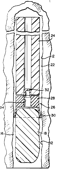
Fig. 1 is a cross sectional view illustrating an
embodiment of a barrier for a dynamic rock anchor, inserted
in a bore, prior to installation of the anchor;
Fig. 2 is a view similar to Fig. 1, following insertion
of the dynamic rock anchor;
Fig. 3 is a cross sectional view of the barrier of Fig.
l; and
Fig. 4 is a cross sectional view of an alternate
embodiment of barrier.
DETAILED DESCRIPTION
A dynamic rock anchor or rod 10 is inserted into a bore
12. A first section 14 of the rod 10 is attached to a first
portion 16 of the bore 12 utilizing grout or fluid 18. It is

2~39~64
Docket No. 1012-IR-RD
envisioned that the grout 16 is a resin-hardner based or
cement based, but the grout may be of any well known type.
A second section 20 of the rod lO may be attached to a
second portion 22 of the bore 12 utilizing a sleeve 24. The
sleeve 24 may be formed from a plastic, elastomeric or other
suitable material. A sleeve 24 is not necessary for the
instant invention.
A barrier 26 prevents the passage of fluid 18 from the
first portion 16 to the second portion 22 of the bore 12.
The barrier consists of a tubular portion 28 and an
interconnected sealing portion 30. A rupture means 32 is
connected to the tubular portion. The barrier may be formed
from an resi]ient material such as plastic, elastomeric or
another suitable material which is impervious to the
particular fluid being used.
The fluid 18 may be grout contained in a fragmentable bag
19 which bursts upon insertion of the rod 10. However, it is
anticipated that this system may be used to prevent passage
of any fluid in a bore from passing to undesirable regions,
for whatever purposes.
An aperture 34 formed in the tubular portion must have a

2~9664
Docket No. 1012-IR-RD
smaller diameter than the rod or bolt 18. The tubular
portion 28 thereby expands to contact the side of the bore 12
when anchor or rod 10 is inserted into the aperture 34. This
contact seals against any passage of fluid between the
tubular portion and the bore 12.
The sealing portion may be formed as a radial, outwardly
flared flange. Prior to insertion of rod 18, the sealing
portion 30 contacts the bore to prevent passage of fluid
between the sealing portion 30 and the bore 12. In this
manner, there is always some restriction against fluid
passage between the barrier 26 and the bore 12.
The rupture means 32 may be formed as a cap portion, or a
diaphragm 36 formed in the aperture 34. The rupture means 32
is strong enough to resist pressure applied by fluid prior
and during insertion of the rod 10, and yet rupture when
pressure is directly applied from the rod 10. After the
rupture means 32 ruptures, a seal 38 will be formed between
the rod and the aperture. In this manner, no fluid will be
able to pass through the aperture.

Representative Drawing
A single figure which represents the drawing illustrating the invention.
Administrative Status

2024-08-01:As part of the Next Generation Patents (NGP) transition, the Canadian Patents Database (CPD) now contains a more detailed Event History, which replicates the Event Log of our new back-office solution.

Please note that "Inactive:" events refers to events no longer in use in our new back-office solution.

For a clearer understanding of the status of the application/patent presented on this page, the site Disclaimer , as well as the definitions for Patent , Event History , Maintenance Fee  and Payment History  should be consulted.

Event History

Description Date
Inactive: Adhoc Request Documented 1997-04-03
Time Limit for Reversal Expired 1997-04-03
Letter Sent 1996-04-03
Grant by Issuance 1995-12-12
Application Published (Open to Public Inspection) 1991-10-20
All Requirements for Examination Determined Compliant 1991-04-03
Request for Examination Requirements Determined Compliant 1991-04-03

Abandonment History

There is no abandonment history.

Owners on Record

Note: Records showing the ownership history in alphabetical order.

Current Owners on Record
INGERSOLL-RAND COMPANY
Past Owners on Record
CLIFFORD A. MCCARTNEY
ROGER GRBAVAC
Past Owners that do not appear in the "Owners on Record" listing will appear in other documentation within the application.
Documents

To view selected files, please enter reCAPTCHA code :


To view images, click a link in the Document Description column. To download the documents, select one or more checkboxes in the first column and then click the "Download Selected in PDF format (Zip Archive)" or the "Download Selected as Single PDF" button.

List of published and non-published patent-specific documents on the CPD .

If you have any difficulty accessing content, you can call the Client Service Centre at 1-866-997-1936 or send them an e-mail at CIPO Client Service Centre.


Document
Description 
Date
(yyyy-mm-dd) 
Number of pages   Size of Image (KB) 
Claims 1995-12-12 5 142
Drawings 1995-12-12 2 62
Cover Page 1995-12-12 1 18
Abstract 1995-12-12 1 28
Description 1995-12-12 7 213
Abstract 1995-12-12 1 28
Cover Page 1994-02-26 1 13
Abstract 1994-02-26 1 24
Claims 1994-02-26 5 123
Drawings 1994-02-26 2 53
Description 1994-02-26 7 180
Representative drawing 1999-07-09 1 21
Fees 1995-04-03 1 53
Fees 1994-03-22 1 39
Fees 1993-03-23 1 39
PCT Correspondence 1995-10-04 1 44
Prosecution correspondence 1993-03-19 2 59
Courtesy - Office Letter 1991-10-23 1 24
Modification to the applicant-inventor 2019-07-10 2 87