Language selection

Search

Patent 2039839 Summary

Third-party information liability

Some of the information on this Web page has been provided by external sources. The Government of Canada is not responsible for the accuracy, reliability or currency of the information supplied by external sources. Users wishing to rely upon this information should consult directly with the source of the information. Content provided by external sources is not subject to official languages, privacy and accessibility requirements.

Claims and Abstract availability

Any discrepancies in the text and image of the Claims and Abstract are due to differing posting times. Text of the Claims and Abstract are posted:

  • At the time the application is open to public inspection;
  • At the time of issue of the patent (grant).
(12) Patent Application: (11) CA 2039839
(54) English Title: LIQUID PAINTING INSTRUMENT
(54) French Title: APPLICATEUR POUR PEINTURE LIQUIDE
Status: Deemed Abandoned and Beyond the Period of Reinstatement - Pending Response to Notice of Disregarded Communication
Bibliographic Data
(51) International Patent Classification (IPC):
  • B05C 17/00 (2006.01)
  • A45D 19/00 (2006.01)
  • A45D 19/02 (2006.01)
  • A45D 34/04 (2006.01)
  • B43K 8/02 (2006.01)
  • B43K 23/12 (2006.01)
  • B43K 27/08 (2006.01)
(72) Inventors :
  • NAKAZIMA, NOBUYUKI (Japan)
(73) Owners :
  • MITSUBISHI PENCIL CO., LTD.
(71) Applicants :
(74) Agent: MARKS & CLERK
(74) Associate agent:
(45) Issued:
(22) Filed Date: 1991-02-19
(41) Open to Public Inspection: 1991-08-21
Examination requested: 1991-02-19
Availability of licence: N/A
Dedicated to the Public: N/A
(25) Language of filing: English

Patent Cooperation Treaty (PCT): No

(30) Application Priority Data:
Application No. Country/Territory Date
16043/1990 (Japan) 1990-02-20

Abstracts

English Abstract


LIQUID PAINTING INSTRUMENT
Abstract
A liquid painting instrument comprising a main shaft
of cross-sectionally oval configuration, a cap of the same
configuration and an O-ring elastically deformable Said O-
ring is put on the front end outer periphery of the main shaft
such that it may be securely fastened to the inner face of the
cap by being elastically deformed following both the
configurations of the main shaft and the cap.


Claims

Note: Claims are shown in the official language in which they were submitted.

THE EMBODIMENTS OF THE INVENTION IN WHICH AN EXCLUSIVE PROPERTY
OR PRIVILEGE IS CLAIMED ARE DEFINED AS FOLLOWS:
A liquid painting instrument comprising a main shaft
(1) cross-sectionally oval, a liquid reserving member such as a
wadding (2) accomodated in the main shaft (1) and impregnated
with a liquid, a rear end sealing member such as a tail plug
(13) for sealing the rear end of the main shaft (1), a front
shaft (4) for holding a painting member such as a painting core
(3), said front shaft (4) being fixedly put on the front end of
the main shaft (1), a cap (5) removably engaging with a front-
ward outer peripheral portion of the main shaft (1), and a
sealing ring such as an O-ring (6) put on a front end outer
periphery of the main shaft (1) such that it may be fastened to
the inner face of the cap (5) by being elastically deformed to
an oval shape following the configuration of the main shaft
(1).
- 5 -

Description

Note: Descriptions are shown in the official language in which they were submitted.


~3~8~g
.j
LIQUID PAINTING INSTRUMENT
BACKGROUND OF THE INVENTION
' (Field of the Invention)
The present invention relates to an ins-trument for
painting liquid cosmetics such as hair dyes, writing inks,
paints, pharmaceuticals, and other liquids.
`~ (Prior ~rt)
, Most of conventional instruments of -this kind are
! cross-sectionally circular in the main shaft thereof and
involve such problem that they are not handy to carry, with an ^-
extra space occupied. Although other different types rarely
exist whose main shaft is cross-sectionally uncircular, they
~ still involve such problem tha-t the cap thereof does not
`~ provide sufficient sealing.
SUMMARY OF THE INVENTION
The present invention is aimed at providing such a
liquid painting instrument that is handy to carry without
occupying any extra space and that the cap thereof is capable
`~ of providing sufficient sealing.
For the purpose of achieving the above aim, the
present invention is such constructed that it comprises a main
shaft cross-sectionally oval, a liquid reserving member such as
~ .
a wadding accomodated in the main shaft and impregnated with a
liguid, a rear end sealing member such as a tail plug for
sealing the rear end of the main shaft, a front shaft for
holding a painting member such as a painting core, said front
shaft being fixedly put on the front end of the main shaft, a
cap removably engaging with a frontward outer peripheral
,. -- 1 --
'
'~
'~ ' ' '
.

2~39~
portion of the main shaft, and a sealing ring such as an O-
ringput on a front end outer periphery of the main shaft such
that it may be fastened -to the inner face of the cap by being
elastically deformed to an oval shape following the
configuration of the main shaft.
BRIEF DESCRIPTION OF T~IE DRAWINGS
I'he presen-t invention may best be understood by
reference to the following description taken in connection with
the accompanying drawings illustratinq a preferred embodiment
of a hair coloring instruments, in which:
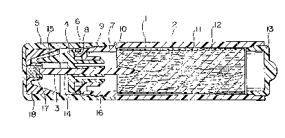
Fig. 1 is a general view in vertical section;
Fig 2 is a front view in a state wherein the cap in
put thereon;
Fig. 3 is a front view in a state wherein the cap is
removed, and
Fig. 4 is a bottom view in the state of Fig. 3.
DEI'AIL,ED DESCRIPTION AND THE PREFERRED EMBODIMENT
,~
Referring now to the drawings, a hair coloring
instrument wi]l be described as an embodimen-t of the present
invention.
A main shaft 1 with front and rear openings has such a
front end portion 7 as diametrally reduced and per se being the
position on which a cap 5 described later is to be pu-t, and at
a front end periphery of the above diametral:Ly reduced portion
7 is formed a stepped portion 8 on which an O ring 6 described
later is to be fitted. While, at such a portion of the
diametrally reduced portion 7 as rather rearward to the stepped
por-tion 8 is formed an engaging projection 9 for engaging with
-- 2
' : '
' :
,

~:~3~
the cap 5. At a position inside the main shaft 1 substantially
the same as the rear end of the above diametrally reduced
portion 7 is formed a stepped portion 10. The main shaft 1 is
configurated cross-sectionally oval as a whole. A wadding 2 is
uscd as a liqu;d reserving member, and it has such construction
that the surface of a bundle of fibres 11 is covered except for
bo-th ends by a water impermeable film 12 of a synthetic resin
and the bundle of fibres 11 is impregrated with a hair dye.
The wadding 2 is inserted from -the rear end opening to the
inside of the main shaft 1 and is held therein with the front
end peripheral edges abutted against the stepped portion 10. A
tail plug 13 is put in the rear end opening of the main shaft 1
and it is airtightly welded to the main shaft 1. On the
stepped portion 8 of the front end peripheral portion of the
main shaft 1 is put an O-ring 6 as a sealing ring. The O-ring
6 is, of course, deformed cross-sectionally oval following the
configuration of the main shaft 1 in the state where it is put
thereon. On the front end portion of the main shaft 1 is put a
front shaft 4 which closes the front end opening of the main
shaft 1 and securely holds the O-ring 6. The main shaft is
perforated substantially at the center portion thereof with a
plurality of through holes 14 arranged in a row along the major
, .i; .
axis of the oval form, and on one side of the through holes 14
''" `
are integrally provided a plurality of comb teeth lS
.
projectiong therefrom. In each of the through holes 14 of the
front shaft 1 is inserted a round stick-like painting core 3
made of a fibre as a painting member. The rear end of the
painting core 3 is inserted into the wadding 2 in the main
-- 3

203g~
shaEt 1. The front end of each of the painting cores 3
projecting forward frorn the fron-t shaft 4 reaches to a position
rather rearward to that of the front end of each of the above
com~ -teeth 15. The cap 5 also of the same oval configuration
in cross-section as that oE the main shaft l is put as above-
mentioned on the diametrally reduced portion 7 of the front end
of the main shaft 1 and is fixed thereon, with an engaging
portion 16 provided on the inside at a portion near the opening
end thereof engaging with the engaging portion 9 of the main
shaft 1. The inner diameter of the cap 5 at a position
corresponding to that oE the above-mentioned O-ring 6 is
designed such that the outer peripheral surface of the O-ring
may closely contact said position in the state where the cap 5
is put on the main shaft 1. Deep in the cap 5 is fixedly
. inserted an inner shaft 18 which centrally holds a felt 17
:; contacting the front end of the painting core 3 when the cap 5
is put on the main shaft 1.
Constructed as above, the present invention can
'~ provide such effects that the cross-sectionally oval
configura-tion of the main shaft makes the instrument thin
enough to be conveniently carried without occupying any extra
-~ space, and that, by fitting the sealing ring which follows the
configuration of the main shaft to be elastically deformed to
an oval form, there can be secured a complete seal with the
sealing ring closely contacting the inner peripheral face of
-the cap irrespective of the non-circular configuration in
. cross-section of -the cap.
;
,~ :
~ ~ 4 ~
"
. ,

Representative Drawing
A single figure which represents the drawing illustrating the invention.
Administrative Status

2024-08-01:As part of the Next Generation Patents (NGP) transition, the Canadian Patents Database (CPD) now contains a more detailed Event History, which replicates the Event Log of our new back-office solution.

Please note that "Inactive:" events refers to events no longer in use in our new back-office solution.

For a clearer understanding of the status of the application/patent presented on this page, the site Disclaimer , as well as the definitions for Patent , Event History , Maintenance Fee  and Payment History  should be consulted.

Event History

Description Date
Inactive: IPC from MCD 2006-03-11
Application Not Reinstated by Deadline 1994-08-20
Time Limit for Reversal Expired 1994-08-20
Inactive: Adhoc Request Documented 1994-02-21
Deemed Abandoned - Failure to Respond to Maintenance Fee Notice 1994-02-21
Application Published (Open to Public Inspection) 1991-08-21
All Requirements for Examination Determined Compliant 1991-02-19
Request for Examination Requirements Determined Compliant 1991-02-19

Abandonment History

Abandonment Date Reason Reinstatement Date
1994-02-21

Maintenance Fee

The last payment was received on 

Note : If the full payment has not been received on or before the date indicated, a further fee may be required which may be one of the following

  • the reinstatement fee;
  • the late payment fee; or
  • additional fee to reverse deemed expiry.

Please refer to the CIPO Patent Fees web page to see all current fee amounts.

Fee History

Fee Type Anniversary Year Due Date Paid Date
MF (application, 2nd anniv.) - standard 02 1993-02-19
Owners on Record

Note: Records showing the ownership history in alphabetical order.

Current Owners on Record
MITSUBISHI PENCIL CO., LTD.
Past Owners on Record
NOBUYUKI NAKAZIMA
Past Owners that do not appear in the "Owners on Record" listing will appear in other documentation within the application.
Documents

To view selected files, please enter reCAPTCHA code :


To view images, click a link in the Document Description column. To download the documents, select one or more checkboxes in the first column and then click the "Download Selected in PDF format (Zip Archive)" or the "Download Selected as Single PDF" button.

List of published and non-published patent-specific documents on the CPD .

If you have any difficulty accessing content, you can call the Client Service Centre at 1-866-997-1936 or send them an e-mail at CIPO Client Service Centre.


Document
Description 
Date
(yyyy-mm-dd) 
Number of pages   Size of Image (KB) 
Cover Page 1991-08-21 1 15
Abstract 1991-08-21 1 13
Claims 1991-08-21 1 20
Drawings 1991-08-21 2 42
Descriptions 1991-08-21 4 133
Representative drawing 1999-07-07 1 20