Language selection

Search

Patent 2040249 Summary

Third-party information liability

Some of the information on this Web page has been provided by external sources. The Government of Canada is not responsible for the accuracy, reliability or currency of the information supplied by external sources. Users wishing to rely upon this information should consult directly with the source of the information. Content provided by external sources is not subject to official languages, privacy and accessibility requirements.

Claims and Abstract availability

Any discrepancies in the text and image of the Claims and Abstract are due to differing posting times. Text of the Claims and Abstract are posted:

  • At the time the application is open to public inspection;
  • At the time of issue of the patent (grant).
(12) Patent: (11) CA 2040249
(54) English Title: FLOAT CHAMBER
(54) French Title: CHAMBRE DE FLOTTEUR
Status: Term Expired - Post Grant Beyond Limit
Bibliographic Data
(51) International Patent Classification (IPC):
  • F16K 31/18 (2006.01)
(72) Inventors :
  • MARTIN, CHRISTOPHER ROY (Australia)
  • MASSEY, RAYMOND DENNIS (Australia)
(73) Owners :
  • ZIP HEATERS (AUSTRALIA) PTY LIMITED
(71) Applicants :
  • ZIP HEATERS (AUSTRALIA) PTY LIMITED (Australia)
(74) Agent: GOWLING WLG (CANADA) LLP
(74) Associate agent:
(45) Issued: 2001-06-05
(22) Filed Date: 1991-04-11
(41) Open to Public Inspection: 1992-10-12
Examination requested: 1998-01-28
Availability of licence: N/A
Dedicated to the Public: N/A
(25) Language of filing: English

Patent Cooperation Treaty (PCT): No

(30) Application Priority Data: None

Abstracts

English Abstract


A Jumper valve for use in the float chamber of a boiling water unit.
The valve consists of a body of circular horizontal cross section having a
vertical outer wall. The inner portion of the valve body includes a
central circular cut-out seat portion to accommodate a cylindrical seal,
the wall of the valve seat between the cut-out portion and the outer wall
being sloped in the manner of the surface of the frustrum of a cone.


Claims

Note: Claims are shown in the official language in which they were submitted.

The embodiments of the invention in which an exclusive property or privilege
is
claimed are defined as follows:
1. A boiling water unit comprising:
a nozzle adapted to permit ingress of water to the unit float chamber;
a temperature sensor:
a float:
a pivot arm tined at one end to the upper portion of the float and adapted to
pivot
about its opposite end: and
a valve seat affixed to the pivot arm, the valve seat having a central
hollowed
portion at least partially surrounded by a ramp surface, and a sealing member
shaped for
accommodation thereof in said hollowed valve seat portion, the arrangement
being such
that water entering said float chamber through said nozzle first contacts said
sealing
member along said ramp surface to contact and activate said temperature sensor
to control
a condition of the water in said float chamber for moving said float to
control the position
of said sealing member relative to said nozzle.
2. A boiling water unit as defined in claim 1 wherein said sealing member has
a substantially flat surface adapted for sealing contact with said nozzle.
3. The boiling water unit of claim 1 wherein said sealing member is of
such dimensions as to loosely fit within said hollowed valve seat portion at
normal
operating temperatures of the unit, but is adapted to expand under pressure
occasioned by
contact of said nozzle, forcing said sealing member against said valve seat,
to at least
substantially close said hollowed valve seat portion when said float rises in
said float
chamber causing said pivot arm to elevate said valve seat and sealing member
to close
said nozzle.
4. A boiling water unit as defined in claim 3 wherein the sealing member
is cylindrical and is of thickness greater than the width of the gap between
said nozzle and
said sealing member when said float rests on the chamber bottom.
5. The boiling water unit of claim 2 wherein said sealing member is of
rubber or a rubber substitute material.
6. A boiling water unit as defined in claim 1 wherein said ramp surface is
frusto-conical and completely surrounds said hollowed valve portion.

Description

Note: Descriptions are shown in the official language in which they were submitted.


CA 02040249 2000-03-29
Float Chamber
This invention relates to float chambers and is more particularly
concerned with float chambers useful in boiling water units such as
depicted and described in the specification of Australian Patent 531449.
In such a conventional boiling water unit, a float chamber is located
beside the upper portion of the boiling water tank, the arrangement being
such that the water level in the float chamber is identical with that in
the boiling water tank. When boiling water is drawn off from the tank, the
water level in both the float chamber and the boiling water tank is lowered
and a float, arranged to float on the water in the float chamber, falls
with the falling water level in the float chamber. A float arm connected
to the float opens a valve when the float has fallen to a predetermined
level, the valve when opened allows cold water under mains pressure to
enter the float chamber.
One problem associated with cistern fed type boiling water units
resides in the capacity to activate the thermostat sensor to switch on the
heating element in the boiling water tank as soon as possible after water
has been drawn from the boiling water tank.
In conventional such boiling water units, a jumper valve has been
provided to alternatively shut off and allow flow of water from the mains
supply to the float chamber. Above the maximum water level in the float
chamber conventional boiling water units incorporate a gauze sleeve housing
a sensor. This sensor is provided for the detection of water temperature
in the float chamber and is adapted to activate the heating element in the
main tank when a drop in water temperature in the float chamber is detected.
Conventional boiling water units have been provided with a tongue on
the float arm for the diversion of some of the water entering the float
chamber from the mains to the aforesaid gauze sleeve, whereupon the sensor,
once sensing the temperature of the water entering the float chamber from
the mains, will activate the aforesaid heating element. This arrangement
has proven satisfactory, but nevertheless is an arrangement which, for
optimum operation of the unit, might be improved upon. A further problem
which has arisen with conventional boiling water units resides in the fact
that the jumper valve adapted to close off the mains water supply has
incorporated a seal of rubber or a rubber substitute adhered to the valve
seat. This seal has tended, with closing pressure, to buckle, thus
providing a less than perfect seal with the mains water
_2_
JMR/936h

~~4~24~
inlet. Clearly, this is undesirable and a further feature which can be
improved upon.
It is an object of this invention to ameliorate the above stated
disadvantages of conventional boiling water units.
This invention in one broad form provides a jumper valve
incorporating a central valve seat, a seal located in but not affixed to
said seat and a ramp surface at least partially surrounding said seat.
By way of example only one embodiment of apparatus in accordance with
this invention will now be described with reference to the accompanying
drawings wherein -
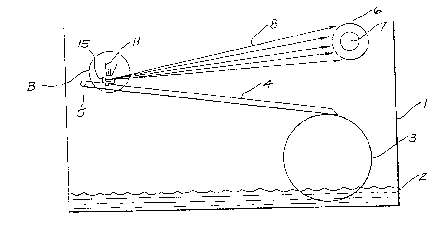
FIG. 1 is a section of a float chamber o~P a boiling water unit;
FIG. 2 depicts the jumper valve indicated at B in FIG. 1 in its open
position;
FIG. 3 depicts the .jumper valve of FIG. 1 in its closed position.
In the drawings, float chamber 1 contains water 2 at a level which
indicates that boiling water has been extracted from the main tank (not
shown>. Float 3 and float arm 4 operate by virtue of pivot 5. Jumper
valve shown generally at 15 is open as depicted in FIG. 2 so that water 10
is permitted to enter float chamber 1 through nozzle 11. Jumper valve 15
is provided with ramp surface 14 and side wall 12. Water 10 entering float
chamber 1 under pressure first strikes jumper valve sealing member 13 and
is then dissipated into float chamber 1, some of water 10 being included in
spray 8 which strikes gauze sleeve 6 which houses sensor 7. Some of the
water incorporated in spray 8 will strike sensor 7 which will operate the
heating element for 'the main tank.
As water continues to enter float chamber 1, float 3 will rise as the
surface level of water 2 rises. In due course, jumper valve 15 will assume
the position indicated in FTG. 3 relative to pipe 11, closing off ingress
of water to float chamber 1. Clearly, under the pressure of water 10,
seal 13 will expand and for this reason an expansion gap is left between
seal 13 and valve seat 16 as depicted in FIG. 2. Under expansion of
sealing member 13, this expansion gap will be fully occupied by the
expanded sealing member 13 which will nest against valve seat 16. When 'the
water level in float chamber 1 is again lowered, and water against enters
float chamber i from pipe 11, jumper valve 15 will again assume its
location relative to pipe 11 as indicated in FIG. 2 and seat 13 will
contract as
JMR/936h

~04(~24~
shos~n in FIG. 2. The preferred thickness of sealing 13 is in the order of
2 millimetres and the preferred opening gap 17 is approximately 1
millimetre.

Representative Drawing
A single figure which represents the drawing illustrating the invention.
Administrative Status

2024-08-01:As part of the Next Generation Patents (NGP) transition, the Canadian Patents Database (CPD) now contains a more detailed Event History, which replicates the Event Log of our new back-office solution.

Please note that "Inactive:" events refers to events no longer in use in our new back-office solution.

For a clearer understanding of the status of the application/patent presented on this page, the site Disclaimer , as well as the definitions for Patent , Event History , Maintenance Fee  and Payment History  should be consulted.

Event History

Description Date
Inactive: Expired (new Act pat) 2011-04-11
Inactive: Entity size changed 2003-03-20
Grant by Issuance 2001-06-05
Inactive: Cover page published 2001-06-04
Inactive: Final fee received 2001-02-28
Pre-grant 2001-02-28
Notice of Allowance is Issued 2000-11-24
Letter Sent 2000-11-24
Notice of Allowance is Issued 2000-11-24
Inactive: Approved for allowance (AFA) 2000-11-09
Amendment Received - Voluntary Amendment 2000-07-19
Amendment Received - Voluntary Amendment 2000-03-29
Inactive: S.30(2) Rules - Examiner requisition 1999-10-15
Amendment Received - Voluntary Amendment 1998-04-17
Letter Sent 1998-03-03
Inactive: Application prosecuted on TS as of Log entry date 1998-03-02
Inactive: Status info is complete as of Log entry date 1998-03-02
All Requirements for Examination Determined Compliant 1998-01-28
Request for Examination Requirements Determined Compliant 1998-01-28
Application Published (Open to Public Inspection) 1992-10-12

Abandonment History

There is no abandonment history.

Maintenance Fee

The last payment was received on 2001-03-28

Note : If the full payment has not been received on or before the date indicated, a further fee may be required which may be one of the following

  • the reinstatement fee;
  • the late payment fee; or
  • additional fee to reverse deemed expiry.

Please refer to the CIPO Patent Fees web page to see all current fee amounts.

Fee History

Fee Type Anniversary Year Due Date Paid Date
Request for examination - small 1998-01-28
MF (application, 7th anniv.) - small 07 1998-04-14 1998-03-18
MF (application, 8th anniv.) - small 08 1999-04-12 1999-03-17
MF (application, 9th anniv.) - small 09 2000-04-11 2000-03-23
Final fee - small 2001-02-28
MF (application, 10th anniv.) - small 10 2001-04-11 2001-03-28
Reversal of deemed expiry 2002-04-11 2002-03-18
MF (patent, 11th anniv.) - small 2002-04-11 2002-03-18
MF (patent, 12th anniv.) - standard 2003-04-11 2003-03-17
MF (patent, 13th anniv.) - standard 2004-04-13 2004-03-17
MF (patent, 14th anniv.) - standard 2005-04-11 2005-03-07
MF (patent, 15th anniv.) - standard 2006-04-11 2006-03-06
MF (patent, 16th anniv.) - standard 2007-04-11 2007-03-08
MF (patent, 17th anniv.) - standard 2008-04-11 2008-03-07
MF (patent, 18th anniv.) - standard 2009-04-13 2009-03-16
MF (patent, 19th anniv.) - standard 2010-04-12 2010-03-19
Owners on Record

Note: Records showing the ownership history in alphabetical order.

Current Owners on Record
ZIP HEATERS (AUSTRALIA) PTY LIMITED
Past Owners on Record
CHRISTOPHER ROY MARTIN
RAYMOND DENNIS MASSEY
Past Owners that do not appear in the "Owners on Record" listing will appear in other documentation within the application.
Documents

To view selected files, please enter reCAPTCHA code :


To view images, click a link in the Document Description column. To download the documents, select one or more checkboxes in the first column and then click the "Download Selected in PDF format (Zip Archive)" or the "Download Selected as Single PDF" button.

List of published and non-published patent-specific documents on the CPD .

If you have any difficulty accessing content, you can call the Client Service Centre at 1-866-997-1936 or send them an e-mail at CIPO Client Service Centre.


Document
Description 
Date
(yyyy-mm-dd) 
Number of pages   Size of Image (KB) 
Cover Page 1993-11-27 1 15
Description 2000-03-29 3 110
Claims 2000-03-29 1 50
Claims 2000-07-19 1 48
Cover Page 2001-05-10 1 30
Claims 1993-11-27 1 20
Abstract 1993-11-27 1 10
Drawings 1993-11-27 1 20
Description 1993-11-27 3 105
Representative drawing 2001-05-10 1 10
Representative drawing 1999-07-06 1 3
Reminder - Request for Examination 1997-12-15 1 117
Acknowledgement of Request for Examination 1998-03-03 1 179
Commissioner's Notice - Application Found Allowable 2000-11-24 1 165
Correspondence 2001-02-28 1 26
Correspondence 1994-05-06 2 46
Fees 1996-12-24 1 40
Fees 1995-12-28 1 31
Fees 1995-03-31 1 44
Fees 1994-04-08 2 65
Fees 1993-03-02 1 38