Note: Descriptions are shown in the official language in which they were submitted.
-1- 2~10~2~
PRQCESS FOR HYDRATING SOFT CONTACT LENSES
The present invention relates to a process for removing
leachable substances from polymeric contact lenses, and
more particularly, for hydrating soft contact lenses by
exchanging leachable substances for water, and still more
particularly, for conducting the leaching or hydrating of
contact lenses while maintaining the orientation of the
lens throughout the process to reduce the need for physical
handling of the lens.
Background of the Invention
Soft contact lenses can be made from hydrophilic polymers
also known as hydrogels by many processes, for esample, by
molding, spin casting or lathe cutting.
During the initial steps of manufacturing hydrogel lenses
by lathe cutting, the hydrogel is maintained in a dry state
so that it may be manipulated on the lathe to cut the
desired optical surfaces. It is then polished, removed
from the lathe, hydrated, inspected and packaged. Spin
cast lenses can be made by subjecting a liguid monomer to a
centrifical force in a mold which has the same shape as the
desired optical surfaces of the lens. As the mold spins,
the monomer is cured to form the lens. The lens is then
typically polished in the mold, hydrated from the mold,
inspected and packaged. Other lenses may be molded from
liquid monomer and catalyst confined in a space between two
mold halves which control the shape of the lens. The
monomer is cured, the mold halves separated and the lens is
hydrated, inspected and packaged. The hydration step in
all of these processes can be time consuming, difficult to
control and somewhat unpredictable so that the
VTN-2S
2 0 ~ ~ ~ 2 ?9
--2--
manufacturing process can be inefficient and sometimes
e~pensive.
In carrying out many of the processes for making contact
5 lenses, significant amoun'cs of manual handling of the lens
may be required. Handling the lens in the dry state can
dirty or scratch the lens. Handling the lens in the
delicate wet state can cause tears and other
imperfections. It would be particularly useful to have a
10 lens manufacturing process which would minimize the
handling of the lens.
When removing a lens from a final package, a user often has
difficulty orienting the lens properly for placement on the
15 cornea of the eye. Sometimes the lens inverts or rolls
over so that the user can inadvertently put the wrong
surface of the lens facing the cornea. It would be
desirable to have a process in which one could control the
orientation of the lens throughout the process and
20 uniformly place the lens in the package so that it could be
consistently removed by the user in the proper orientation
for placement on the cornea. It would also be useful to
have a package specially designed to maintain the
orientation of the lens during storage and shipping.
The Assignee of the present invention molds its contact
lenses in two-part molds like those shown in U.S. Patents
Nos. 4,565,348 and 4,640,489. Liquid monomer is placed in
a concave mold surface and then covered with a lid and
30 cured, for e~ample, by ultraviolet light. During
polymerization, particularly of hydrogels, the lens tends
to shrink. To reduce shrinkage, the monomer is polymerized
in the presence of an inert diluent like boric acid ester
as described in U.S. Patent No. 4,495,313. The inert
35 diluent fills up the spaces in the hydrogel lens during
VTN-25
_ 3 _ 2040520
polymerization. The diluent is subsequently
exchanged for water during the hydration process.
Since the boric acid ester is inert but water
soluble, it can be used to fill up the spaces in the
hydrogen during polymerization and minimize
shrinkage of the lens during polymerization and then
exchanged for water to hydrate the lens. This
process significantly improves the reliability of
the manufacturing process and increases the ability
to predict and maintain the dimensions of the lens
during processing.
The process of exchanging the diluent for water and
hydrating the lens can be very time consuming. The
two-part mold is opened or demolded and the lenses
are assembled in large groups and placed in a
leaching tank for several hours. The leach tank
includes heated water, small amount of surface-
active agents (surfactants) and salts. When the
lenses are inserted in the leach tank they
immediately expand in the presence of water and
release from the mold in which they were molded.
The boric acid ester diluent hydrolyzes into
glycerol and boric acid leaving the water behind in
the matrix of the lens to thus exchange diluent for
water to partially hydrate the lens.
Salts and a pH buffer are used in the water so that
the water placed in the lens has osmolality and pH
substantially similar to that of human tears so that
the lens will not irritate the eye when it is
inserted by the user. If the polymer from which the
lens is made has ionic characteristics the buffer
neutralizes any ionic species in the lens. That
neutralization causes some temporary destabilization
of the dimensions of the lens and requires an
extended period of time to complete.
2 ~ J ~
--4--
The leach solution is then drained and the lenses are
transferred to a rinse tank where the removal of diluent
and surfactant continues for another estended period of
time. The rinse solution is then drained and the lenses
are transferred to a large equilibration tank filled with
heated water and salts for completion of diluent and
surfactant removal and equilibration of the lens for
several more hours. The e~uilibration step entails
completion of the neutralization of any ionic species in
the polymer from which the lens is made and final hydration
to the final water content and final dimensionals. The
lens is then removed from the equilibration tank and rinsed
in clean saline and transferred for inspection and then
packaging.
It would be desirable to have a process for hydrating
lenses that would reduce the amount of water, associated
chemicals, like surfactants and salts, and the amount of
time necessary to complete hydration and control the
orientation of the lens.
It would also be useful to control the orientation of the
lens during the hydration process so that it could
consistently be placed in the package with the correct
orientation.
Summary of the Invention
The present invention alleviates many of the problems of
the prior art by providing a process for hydratinq contact
lenses which is much faster, cheaper and predictable than
the methods previously used. When used to hydrate a lens
made in a two-part mold like those disclosed in U.S. Patent
Nos. 4,564,348 and 4,640,489 in the presence of a diluent
like that disclosed in U.S. Patent 4,495,313, the present
VTN-25
CA 02040~20 1997-08-29
process results in significant time and cost savings
for hydrolyzing the diluent and exchanging it for
water.
S The process of the present invention may be used for
extracting leachable substances from a polymeric
contact lens blank which has an anterior and a
posterior surface. The lens blank is placed in a
first carrier element with the anterior surface of
the lens blank oriented toward a first surface of
the first carrier element. The first carrier
element and the lens blank are then covered with a
second carrier element. The first and second
carrier elements cooperate to define a cavity to
confine the lens blank and maintain the orientation
of the lens blank without permitting it to invert or
roll over. A fluid flow is then introduced into the
cavity about the anterior and/or posterior surfaces
of the lens and then permitted to flow out of the
cavity to flush the leachable substances out of the
lens blank. In this way, it is possible to extract
a variety of substances like unreacted or partially
reacted monomer or inhibitors using a variety of
solvents like water, alcohol, a mixture of water and
alcohol or any other organic solvent depending upon
the material one wishes to leach from the lens
blank.
The use of the first and second carrier elements to
confine the lens in a cavity permits the removal of
the leachable substance or the diluent exchange and
hydration and washing to be conducted in a step-wise
fashion simultaneously. A small quantity of clean
fresh leaching fluid or hydrating water can be
3s introduced into the cavity for a short period of
time and then be flushed out to be replaced by a
second quantity of clean, fresh fluid.
2 ~
--6--
Since the mechanism for removal of leachable substances is
mass transfer, this step-wise estraction maintains the mass
concentration gradient high to speed up extraction.
This step-wise fluid introduction and flushing can be done
any desired number of times. This significantly reduces
the amount of solution that is needed and improves the
efficiency of the leaching and hydration.
The process of the present invention is particularly well
suited to lenses which are manufactured in a two-part mold
like those described in U.S. Patent Nos. 4,565,348 and
4,640,489 in the presence of a diluent like that described
in U.S. Patent 4,485,313. If the diluent used is a boric
acid ester, the fluid used can be water. The ester is
hydrolyzed in the presence of water to eschange the diluent
for water and thus hydrate and wash the lens. When
hydrating this type of lens, the hydration/washing/diluent
e~traction is preceded by the steps of opening the two-part
mold leaving the lens blank in either the concave or conves
mold part. The mold part in which the lens blank is left
is then covered with the first carrier elements so that an
optical surface of the lens blank is oriented toward a
first surface of the first carrier element. The lens blank
is then released from the mold part in which it was left,
preferably by submerging the mold part in which the lens
blank was left and the first carrier element together in
water so as to initially hydrate the lens blank and cause
it to separate from the mold part. It is desirable but not
required that the mold part and the first carrier element
be submerged at an angle to the horizontal so that the lens
blank moves under the force of gravity from the mold part
in which it was left to the first carrier element without
trapping air between the lens blank and the first carrier
VTN-25
2 ~ J ~ ~
element first surface and without permitting the lens blank
to invert or roll over.
After the lens blank is released into the first carrier
element, the first carrier element is covered with the
second carrier element as described above and a fluid flow
is introduced to flush leachable substances from the
contact lens and to wash and hydrate the lens.
After the flushing, the lens can be deposited into an
inspection carrier by one of two methods. The first of the
two methods is to partially drain the cavity formed by the
first and second carrier elements to deposit the lens blank
in one of them. The remaininq of the first or second
carrier element is then removed and a third carrier element
is introduced to which the lens is transferred by
compressed air, gravity or a fluid flow and attached by,
for esample, surface tension. The third carrier element is
then separated from the remaining of the first or second
carrier elements and the third carrier element is oriented
over an inspection carrier. The third carrier element is
submerqed in the inspection carrier so as to break the
surface tension which hold the lens on the third carrier
element and allow the lens to float freely into the
inspection carrier. This third carrier element preferably
has a conve~ surface to which the posterior surface of the
lens blank is attached by surface tension. The dimensions
of the conve~ surface of the third carrier element are
chosen so that they can be easily submerged in the
inspection carrier.
The second means for transferring the lens blank to the
inspection carrier is to drain the cavity defined between
the first and second elements and then to use air pressure
to transfer the lens to the one of the first or second
VTN-25
2040520
carrier elements that has a convex surface that will
mate with the posterior surface of the lens. The
transferring is done preferably by air pressure so
that the lens attached by surface tension to the
appropriate carrier element. The appropriate
carrier element is then aligned over an inspection
carrier and transferred to the inspection carrier by
a flow of compressed air or a flow of liquid.
It is preferred that the water used to hydrate the
lens and which is used throughout the process of
releasing the lens and hydrating and inspecting the
lens is deionized water without any salts so that
the time consuming ionic neutralization of the
polymer from which the lens blank may be made does
not have to occur during the hydration process.
When deionized water is used, the final step of the
process is to introduce buffered saline solution to
the inspection carrier after the inspection has been
completed. The inspection carrier which may also be
the final package for the lens is then sealed and
final lens equilibration (ionic neutralization,
final hydration and final lens dimensioning) is
accomplished in the package at room temperature or
during sterilization.
The use of deionized water is an important step in
this process because it allows the time consuming
ionic neutralization to be done essentially outside
the hydration process after the lens has been
packaged and sealed.
According to a further broad aspect of the present
invention, there is provided a process for hydrating
hydrophilic polymer contact lens blank, to form a
B
2040520
- 8a -
hydrogel contact lens. The lens blank has an
anterior optical surface and posterior optical
surface. The lens blank is placed in a first
carrier element with an optical surface of the lens
blank oriented towards a first surface of the first
carrier element. The lens blank is covered with a
second carrier element with the other optical
surface of the lens blank oriented toward a first
surface of the second carrier element. The first
and second carrier elements cooperate to define a
cavity to confine the lens blank therein and
maintain the orientation of the lens blank anterior
and posterior surfaces without permitting the lens
blank to invert or roll over. The flow of water is
provided in the cavity through the first carrier
element and about the surface of the lens blank
facing the first carrier element first surface. A
flow of water is also provided into the cavity
through the second carrier element and about the
lens blank. A flow of water is also provided out of
the cavity. The flow of water permits hydration of
the lens blank and extraction of impurities.
These and other features and advantages of the
present invention will become more apparent when
taken in conjunction with the following detailed
description of the preferred embodiments and the
following drawings.
~,
- 9 -
Brief Description of the Drawings
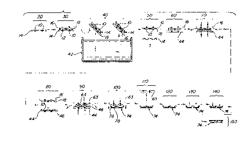
Fig. 1 shows a schematic representation of the entire
process;
Figure 2 shows a perspective view of a lens made in a
multiple cavity mold shown in perspective and partly in
phantom ready for assembly to a set of first carrier
elements shown in perspective for use during the mold
release steps of the process;
Figure 3 shows a perspective view of a set of second
carrier elements to be assembled with the first carrier
elements and to be used during the hydration steps of the
process;
Figure 4 shows a perspective view of a single one of the
first carrier elements shown in Fig. l;
Figure 5 shows a cross-sectional view of a single one of
the first carrier elements shown in Fig. 2 and the second
carrier element shown in Fig. 3 assembled together with a
lens placed in the cavity defined between the first and
second carrier elements; and
Fiq. 6 shows a perspective view of a third carrier element
used to transfer the hydrated lens to an inspection carrier
which also serves as part of the final package of the lens.
Detailed Description of the Preferred Embodiment
Referring now to Fig. 1, there is shown a schematic
representation of the entire process of the present
invention which has three major components, namely:
release
VTN-25
2 ~
--10--
of the lens from the mold in which it is made; hydration,
washing and diluent e~traction of the lens; and, the
inspection and packaging of the lens.
The present process is used most beneficially in connection
with lenses that are manufactured in two-part molds of the
kind shown in U.S. Patent Nos. 4,565,348 and 4,640,489 in
the presence of a diluent, according to the process
disclosed in is U.S. Patent No. 4,495,313. As will be
disclosed later, it is also possible to use the hydration
step to hydrate dry hydrogel lens blanks made by lathe
cutting or spin casting or other manufacturing processes.
The overall process of the present invention will now be
discussed in connection with the schematic representation
of the various steps of the process shown in Fig. 1
together with reference, when necessary, to the remaining
figures which show some of the important apparatus used to
carry out the process.
Contact lens blank are made in two-part molds like those
shown in U.S. Patent Nos. 4,565,348 and 4,640,489, by
polymerizing monomer in the presence of a catalyst and a
diluent with ultra violet light or heat according to the
process described in U.S. Patent No. 4,495,313. After the
polymerization process is completed, the two halves of the
mold are separated (this is called demolding) typically
leaving the contact lens blank 10 in concave lens part 12
(see Fig. 2). Fig. 2 shows a mold frame 14 with eight
concave mold cavities in which eight lenses can be made at
once. For convenience in Fig. 1, the concave mold frame 14
is shown in an end view so only two mold cavities 12 are
shown in Fig. 1. Any convenient number of mold cavities
could be used on frame 14. There is also a conve~ mold
frame having a similar number of mold parts which is not
~TN- ~;
2040520
-- 11 --
shown in the present application but is shown in
U.S. Patent No. 4,565,348. The first step after
demolding is the first station in the process
outlined in Fig. 1 and is identified by reference
character 20.
At the second station 30 in the process of Fig. 1, a
first carrier frame 16 carrying eight first carrier
elements 18 is assembled over concave mold frame 14
so that each first carrier element 18 fits over each
concave mold part 12 to confine each of lens blanks
10 in a cavity which is small enough to prevent the
lens from rolling over or inverting during
subsequent processing steps.
First carrier element 18 is shown in perspective in
Fig. 4 as an individual element which can be
assembled into first carrier frame 16 shown in
phantom in Fig. 4. First carrier element 18 has a
generally cylindrical shape defined by a surrounding
side wall 22 in which is placed a plurality of
openings 24 whose purpose will be explained later in
the application. Openings 24 are preferably
circular or slots but can be any convenient shape.
First carrier element 18 has a convex surface 26
which combines with the interior surface 28 of
surrounding side wall 22 to form a recess 32. First
carrier element 18 has a boss 34 which fits into a
corresponding bore 36 in first carrier frame 16.
Recess 32 in first carrier element 18 combines with
the outer flange of mold part 12 to form a cavity
confining lens blank 10. First carrier element 18
has a bore 38 extending through boss 34 and convex
surface 26 to provide fluid communication through
first carrier element 18 into recess 32 as will be
explained later in the application when discussing
js;
2040520
- lla -
the hydration/washing/extraction steps of the
process.
B
2 0 ~ g n~
--12--
At the ne~t station 40 in the process, first carrier frame
16 and concave mold frame 14 are rotated approsimately 135~
the counterclockwise direction so that first carrier frame
16 is below concave mold frame 14, but the two are oriented
at an angle of approximately 45~ to the horizontal. They
are then submerged in a tank 42 of deionized water at a
temperature greater than the glass transition temperature
of the material from which lens blank 10 is made.
In the present invention, the lens blank is preferably made
of HEMA (hydrosyethylmethacrylate). The deionized water
also includes small amounts of sufactants to assist in
releasing lens blank 10 from concave mold part 12 ~ As lens
blank 10 is submerged, it immediately swells in the
presence of the deionized water and the swelling-helps
release lens blank 10 from contact with concave mold part
12 ~ The reason for orienting frames 14 and 16 in an angle
of appro~imately 45~ to the horizontal is to permit lens
blank 10 to drop downwardly from concave mold part 12 onto
the conve~ surface 26 of first carrier element 18 without
trapping air between the posterior surface of lens blank 10
and conve~ surface 26 of first carrier element 18. These
angles are preferred but any convenient angle may be used.
The use of deionized water in release tank 42 is
particularly important when using lens blanks 10 made of
materials which have ionic characteristics. If one were to
use water laden with various salts, one would start the
neutralization process of any ionic species in the lens
material. This neutralization takes an e~tended period of
time and causes some temporary instability in the dimension
of the lens.
After a specified period of time when the lens has reached
stable dimensions, preferably about five (5) minutes, the
VTN-25
2 ~''
assembly of concave mold frame 14 and first carrier frame
16 are removed from release tank 42 and held at an angle
for a short period of time to permit the drainage of escess
water from the cavity defined between each first carrier
element 18 and its corresponding concave mold part 12. The
water drains out of first carrier elements 18 through holes
24 in the side wall of each first carrier element 18. The
posterior surface of lens blank 10 thus attaches itself by
surface tension to con~es surface 26 of first carrier
element 18.
At the nest station 50 in the process, first carrier frame
16 is rotated back so it is on top of concave mold frame
14. Concave mold frame 14 is dropped from first carrier
frame 16 leaving lens blank 10 attached to conve~ surface
26 of each first mold carrier 18.
At the ne~t station 60 of the process, a second carrier
element frame 44 is placed under first carrier element
frame 16 and aligned to form a cavity confining lens blan~
10 so that it may not roll over or invert auring subsequent
processing steps. Second carrier element frame 44 is shown
in more detail in Fig. 3. Second lens carrier frame 44
holds an array of preferably eight second carrier elements
46, but any convenient number of second carrier elements 46
can be used. Referring now to Fig. 5, it can be seen that
second carrier element 46 has a generally cylindrical shape
with a surrounding side wall 48 and a concave surface 52
defining a recess 54 (See Fig. 3).
The carrier elements 18 and 46 and carrier frames 16 and 44
used in this process are more particularly described in a
co-pending patent application entitled ~Chamber for
Hydrating Contact Lenses~ assigned to the assignee of the
present invention and filed on the same date as the present
VTN-25
-14- 2 ~ 2 ~
application. The entirety of that patent application is
hereby incorporated in this patent application by reference.
Referring again to Fiq. 5, it can be seen that the inside
diameter of surrounding side wall 48 of second carrier
element 46 receives the outside diameter of surrounding
side wall 22 of first carrier element 18 in a close fit.
Openings 24 in side wall 22 of first carrier 18 estend
above the upper surface of 56 of surrounding side wall 48
of second carrier element 46. The confronting conves
surface 26, inside wall 28 and concave surface 52 provide a
cavity 55 for confining lens blank 10 so that it will not
roll over or invert during subsequent processing steps.
Second carrier element 46 includes a cylindrical boss 58
similar to boss 34 of first carrier element 18 to permit
second carrier element 46 to be assembled easily to second
carrier frame 44. Second carrier element 46 includes a
bore 62 estending through boss 58 and concave surface 52
into recess 54. It can be appreciated from Fig. 5 that the
cavity 55 defined by the confronting surfaces of first and
second carrier elements 18 and 46 can be connected to a
source of fluid through either or both of bores 38 and 62
which fluid can esit cavity 55 through openings 24 in side
wall 22 of first carrier 18. The direction of flow can be
varied according to the requirements of the
process.
At the ne~t station 70 in the process of the present
invention, deionized water is introduced through bores 38
and 62 simultaneously to fill cavity 55 to permit the
estraction of impurities from lens blank 10. In the
preferred embodiment, lens blank 10 contains an inert but
water soluble diluent, for esample, a boric acid ester of
the kind described in U.S. Patent No. 4,495,313. For
diluent containing lenses, the purpose of the
VTN-25
2 ~
-15-
hydration/washing/estraction step is also to eschange the
diluent for water. When the diluent containing lens blank
10 is esposed to deionized water, the ester hydrolizes to
glycerol and boric acid which leave lens blank 10 and goes
into the fluid contained in cavity 55. This eschange is
driven by the physical phenomenon of mass transfer and
depends on the concentration gradient of the impurities and
the products of hydrolysis between lens blank 10 and the
fluid in the cavity 55. As the estraction continues the
concentration gradient diminishes and the process slows
down. Thus, it has been found useful to conduct the
hydration/washing/estraction in a series of discrete steps
where a quantity of fresh liquid is introduced into cavity
55 through one or both of bores 38 and 62 and leaving the
liquid in cavity 55 by blocking the flow through bores 38
and 62.
After the hydration/washing/estraction has proceeded for a
period of time, on the order of a few minutes, openings 38
and 62 are unblocked permitting a new quantity of fluid to
be introduced into cavity 55 while flushing the old fluid
out of openings 24. When cavity SS is filled with fresh
deionized water, openings 38 and 62 are aqain blocked and
lens blank 10 is permitted to hydrate for a further period
of time in the deionized water confined in cavity 55. This
step-wise estraction continues for a predetermined number
of times until the estraction of diluent and impurities is
complete. The number of estractions is dependent on the
guantity of fluid used and the time the lens is allowed to
soak prior to the nest e~traction. I have found that sis
e~tractions in deionized water will satisfactorily complete
the estraction using approsimately 2.5 ml of water. I have
determined esperimentally that the glycerol concentration
in the deionized water after estraction lens hlan~ 10 is
~TN-25
~0~ 2~
-16-
reduced well below detectable limits by the sisth
estraction.
It would also be possible to have a continuous flow of
deionized water through cavity 55 and I believe that that
would provide satisfactory results, however, I prefer to
use the step-wise e~traction discussed above.
This e~traction step could also be used to remove any
leachable substance from any contact lens blank, whether
the lens blank was made by lathe cutting, spin casting,
molding or some other method. Dry lathe cut or spin cast
lens blanks 10 could be leached starting at station 50 in
this process and continuing through stations 60 and 70.
Dry lens blanks 10 can be placed in first carrier frame 16
and then covered with second carrier frame 44 and subjected
to estraction with a desired solvent which can be water,
alcohol, a misture of water and alcohol or any organic
solvent suitable to remove the substance one wishes to
leach from the lens blank. Once the leaching is
accomplished, the process can continue through additional
processing steps.
One proceeds from station 70 where the
hydration/washing/e~traction is accomplished to stations
80, 90, 100 and 110 where lens blank 10 is transferred to
an inspection carrier 74 which may be part of the final
package for lens blank 10. At station 80, first carrier
frame 16 is removed leaving the hydrated lens blank 10
settled in concave carrier element 46. Then second carrier
frame 44 is moved to station 90 where it is covered with a
third carrier frame 63 which contains a number of third
carrier elements 64 shown particularly in Fig. 6.
VTN-25
3 ~,?,~, ~7
-17-
Third carrier element 64 is qenerally cylindrical and has a
conves surface 66, a boss 68 for attaching it to its third
carrier frame 63 and a bore 72 estending through boss 72
and conves surface 66 to permit the flow of fluid through
third carrier element 64. It will be noted that third
carrier element 64 has no surrounding side wall so that, as
will be esplained later, concave surface 66 can be
submerged within inspection carrier 74. If third carrier
element 64 were to have a surrounding side wall, that side
wall would make it ~ re difficult to place the lens into
inspection carrier 74.
As shown at station 90 in Fig. 1, lens blank 10 is then
transferred from the concave surface 52 of second carrier
element 46 by for esample, a flow of pressurized fluid. I
prefer compressed air. Lens blank 10 then attaches itself
by surface tension to conves surface 66 of third carrier
elements 64 on third carrier frame 63. Second carrier
frame 44 is then removed and third carrier frame 63 is
transferred to station 100 and oriented above inspection
carrier 74 which contains a plurality of individual
packages 76 defining recesses 78. A quantity of deionized
water is then introduced through bores 72 to transfer lens
blank 10 to recesses 78 of inspection carrier 74.
The process at stations 80, 90 and 100 may be modified.
After the lens is hydrated at station 70, lens blank 10
settles by gravity against concave surface 52 of second
lens carrier 46. Compressed air may then be introduced
through bore 62 to transfer the lens back to conves surface
26 of first carrier element 18. The posterior surface of
lens blank 10 will attach itself to conves surface 26 by
surface tension. First carrier frame 16 is then
transferred to a location above inspection carrier 74.
Compressed air or other fluid, for esample, deionized water
T~-25
2~ ~J~
is introduced through bores 38 of first carrier elements 18
to deposit lens blank 10 in recesses 78 of inspection
carrier 74. The surrounding wall 22 of first carrier
elements 18 does not permit lens carrier 18 to be submerged
5 in recesses 78 of inspection carrier 74, requiring lens
blank 10 to be forced off conves surface 26. Although this
alternative process is satisfactory, I prefer to use the
process described above for stations 80, 90 and 100 where
third carrier elements 64 are used.
At station 110, third carrier frame 63 is removed and
inspection carrier 74 is moved to an inspection station 120
where it may be inspected manually or by automated optical
machinery.
At station 130, the deionized water is removed from
recesses 78 of inspection carrier 74 and replaced at
station 140 with a saline solution which has a pH and
osmolality compatible to that of the tears of the human
20 eye. Alternately, an aliquot of concentrated brine
solution may be added to the deionized water such that the
final solution has the same pH and osmolality mentioned
above. Saline solution is used so that when the user
removes the lens from the package ready to insert on to
25 ones cornea, the pH and osmolality of the lens will be
balanced with that of the eye so that the lens will not
irritate the eye when inserted.
If the material from which lens blank 10 is made has an
30 ionic characteristic, the salts in the saline solution will
neutralize that ionic species. However, that
neutralization can be done in the final package on the
shelf outside the remainder of the manufacturing process.
VTN-25
2~' ~ .. 2 ~
--19--
At station 150, inspection carrier 74 is packaged, for
esample, hermetic seal with a material that does not permit
liquid to transfer through the package material.
It will be noted that the shape of the recess 78, in which
the lens is deposited at station 100, is important to keep
the lens properly positioned for inspection. Thus, it can
be seen from Fiq. 6 that recess 78 is generally spherical
in shape with a radius of curvature larger than the radius
of curvature of the conve~ surface of lens blank 10,
permitting lens blank 10 to center itself on surface 52 by
gravity. Surface 52 provides a low friction for wet lens
blanks to let the lens stay on center as inspection carrier
74 is moved from station to station through the inspection
process. It will also be noted that the size of recess 78
is small enough to confine the lens after it is sealed into
its package so that it may not roll over or invert during
storage or shipment. This assures that the lens is always
in the proper orientation when the package is opened so
that the user will always be assured that the lens is in
the same position ready for placement on the cornea of the
eye.
It can be seen that the present process substantially
reduces the amount of water, chemicals and time needed to
hydrate the lens and do the diluent eschange. The use of
deionized water is a particularly useful step in that it
postpones the neutralization of the ionic species in the
polymer from which the lens is made.
The present process also provides control of the
positioning of the lens throughout the process so that it
is always oriented properly and can be placed in the
package in a consistent manner all the time so that when
one removes the lens from the package one knows that it is
~JT~-25
3 2 ~:
-20-
properly oriented for placement on the eye. The present
process also substantially reduces handling of the delicate
lens.
The time reductions accomplished in the present process are
significant. The release step is accomplished in less than
ten (10) minutes normally less than five ~5) minutes. The
hydration/washing/estraction process is accomplished in
less than a half hour at room temperature. The
equilibration or acid neutralization process and final
dimensional stabilization of the lens is accomplished in
less than two hours at room temperature after lens blank 10
has been placed and sealed in its final package.
The present invention has been described in conjunction
with preferred embodiments. Those skilled in the art will
appreciate that many modifications and changes may be made
to the preferred emboidments without departing from the
scope of the present invention. It is, therefore, not
intended to limit the present invention e~cept to set forth
in the appended claims.
VTN-25