Note: Descriptions are shown in the official language in which they were submitted.
2 ~ 2 8
CHAIR BACK AND SEAT ADJUSTMENT MECHANISM
Background of the I~vention
Chair back adjustment devices using a series of
engaging plates and a clamp are old (U.S. Patent No.
4,062,587) and chair seat adjustments using a threaded stem
have also ~een proposed (V.S. Patent No. 3,712,672).
SummarY Of The Invention
Broadly, the present invention comprises a chair
10 adjustment mechanism having an elongated horizontal
pedestal supported frame which frame remains in its
horizontal position during chair operation. Pivotally
mounted on the frame is a chair seat support and also
pivotally mounted on the frame is a back bracket for
supporting a back rest. A set of slotted plates are
mounted on the frame and a second set on the back bracket.
The tilt of the back and seat is controlled by a locking
I stem passing through the slots of both sets of plates.
It is a feature of the invention that both seat
and back tilts can be selected by the chair operators and
such positions maintained by operating a single control
handle.
25 Brief Description Of The Drawings
Fig. l is a perspective view of the chair
adjustment mechanism seen from the bottom;
Fig. 2 is a partial side elevational view of the
mechanism;
--2--
~0 ~28
Fig. 3 is a bottom view of the mechanism;
Fig. 4 is a partial top view of ~he mechanism
seat support housing and its seat mount cross plates.
Description Of The Preferred Embodiment
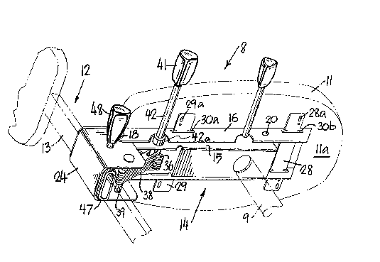
In the drawings, chair 8 with pedestal 9
(partially) shown includes oval seat 11 with seat bottom
lla, back 12, back support post 13 and seat and back
adjustment mechanism 14.
Adjustment mechanism 14 includes pedestal
horizontal frame piece 15 which remains in a substantially
horizontal position throughout operation of chair 8.
Pivotal seat support housing 16 which pivots about pin 20
mounted in frame piece 15 with seat-bottom-engagement piece
17 and spaced-apart vertical pieces 19 (at the right side
as viewed by the person sitting in chair 8) and piece 21 on
the left side. Pieces 17, 19 and 21 form a U-shape in
cross-section and preferably are integrally formed.
Frame piece 15 supports a back bracket 24 pivotal
about pin 18. Pedestal post 9 is raised by operation of
control handle 26 employing a hydraulic arrangement (not
shown). Seat support housing 16 is secured to seat bottom
lla of seat 11 with forward cross mount plate 28 and
rearward cross mount plate 29. Notches 31 in plates 28, 29
interlock with indentations 17a in seat-bottom-engagement
piece 17 (see Fig. 4).
Also pivotal about pin 18 of seat support housing
16, is a bank or set of seat friction plates 3Ç. A second
set of back friction plates 38 are mounted on pin 39 of
back bracket 24. Both sets of friction plates 36, 38 have
35 slots 36a, 38a. The sets of friction plates 36, 38 are
2 ~ 2 ~
interleaved and are compressed by ad~ustment control handle
41 having threaded stem 42. Stem 42 carries limit ring
42a. Handle 41 is mounted parallel to pins 18 and 39 and
carries a threaded portion to permit urging the sets of
plates 36, 38 together in lock posi~ion or releasing the
plates for adjustment.
Turnin~ to ~igs. 2, 3 and 4, spring 43 urges back
bracket 24 to a position in which back friction plates 38
move left in Fig. 2 until the end of slot 38a engages stem
10 42. In that position, back post 13 is angled from the
vertical position toward a person sitting in the chair.
Fig. 2 shows the back post 13 urged against spring 43 to
the vertical position. 5tem 42 of handle 41 carries
washers 44a, 44b, and collar 46 and stem nut 42b along with
both sets of friction plates 36, 38. The washers 44a, 44b,
collar 46, and plates 36, 38 are confined between fralne
sides 15a, 15b for tightening and relaxation (Fig. 3). The
tightening of plates 36, 38 is accomplished by turning
handle 41 which turns stem 42, which through its threaded
20 end causes threaded nut 42b held against turning in a
recess in vertical piece 19, to translate along stem 42
toward handle 41. As nut 42b moves in this direction it
urges collar 46 against plates 36, 3~ which plates are
confined by washers 44a, 44b. Relaxation o~ plates 36, 38
i5 accomplished by turning stem 42 in the opposite
direction.
Back post 13 is adjustable up or down as housed
in oval plastic grip piece 47. Grip piece 47 has a wedge
section 51 attached, which complements the angle of metal
wedge piece 52 which slides back and forth on stem 49.
Depending on the way knob 48 on stem 49 is rotated, it will
increase or decrease pressure against back post 13
35 positioned in piece 47 so that back assembly 12 is locked
_4_ 2~
in place or released at will. Back assembly 12 with post
13 moves up or down for adjustment of back to correct
height~ Threaded stem 49 carries back adjustment handle
48.
Turning to Figs. 3 and 4, cross plates 28, 29 are
slidable for assembly purposes through rectangular seat
support openings 30a, 30b in each side of the sides 19, 21
of chair support housing 16. Plates 28, 29 are inserted
until their notches 31 match seat support notches 17a
10 permitting plates 2~, 29 to be moved upwardly until
indentations 17a and notches 31 interlock (Fig. 4). In
this position, cross plates 28, 29 are below but touching
the underside of piece 17. In this position, plates 23, 24
are screwed, bolted or otherwise secured to seat bottom
lla. Piece 17, as held against seat bottom by fasteners
through holes 28a, 29a, cannot move in any direction.
To accomplish dual adjustment of seat and back
(or if only one adjustment is desired), adjustment handle
20 41 is turned to release the banks of friction plates 36, 38
and permit the seat housing 16 and back bracket 24 to be
moved to any angular position vis-a-vis frame 15 consistent
with the length o the slots 36, 38 and cross-sectional
size of stem 42 therein. ~s the plates move about their
25 pivots control handle 41, mounted in frame 1~, remains in
the slots 36a, 38a. once the seat 11 and back 12 are at
the desired angles, control handle 41 including its stem 42
is turned to tighten the plates 36, 38 together until they
are tight enough that normal chair use will not exert
forces which permit sliding movement between or among the
plates 36, 38. The height of back post 13 is then,
optionally, also adjustable as described above.