Note: Descriptions are shown in the official language in which they were submitted.
~Q~~ ~ ~~~
SUPPORT LINKAGE FOR MOUNTING A HEADER ON A SUPPORT FRAME
BACKGROUND OF THE INVENTION
This invention relates to a support linkage for
supporting a header on a support frame of a crop harvesting
machine.
The present invention is particularly but not
exclusively designed for use with swathers. which may be of the
self propelled or pulled variety.
Self propelled swathers generally comprise a
tractor unit which has a frame carried by a pair of driven
front wheels which straddle the swath and hence are positioned
at respective sides of the driver platform so as to extend
downwardly therefrom. Conventionally the wheels are driven by
hydraulic motors mounted at a lower end of the wheel support
struts. The rear wheels supporting the frame are generally
castor wheels which are positioned at the rear of the platform
and again spaced widely to straddle the swath. Pull-type
swathers include a frame mounted on a pair of spaced ground
wheels with the frame attached to a hitch pole for connection
to a separate tractor unit.
In both cases the frame is designed to accomodate
different headers which can vary significantly in width and
weight depending upon the crop and depending upon the land
- 1 -
2~~~~~~
conditions. It is necessary therefore for the swather frame to
be designed to accomodate headers of significantly different
weight and to allow adjustment of the cutting height of the
header. Furthermore the header must be mounted so that it can
float that is it can fall to a required cutting height but can
lift away from that height if it comes into engagement with the
ground or with any other obstacle to prevent damage. In
addition the header must be raisable under control of the
operator so that it can be raised from certain obstacles and so
that it can be lifted away from the ground for transportation
when inoperative.
Various designs of support linkage have
previously been proposed for holding the header relative to the
frame in a manner which accomodates the above requirements.
Generally the linkage includes left and right linkages each
seperately connected to the frame. Generally each support
linkage comprises a top links a bottom link and a float spring
arrangement which tends to lift the header around the pivotal
links from a lower stop position to enable the header to float
away from contact with any obstacle on the ground. One example
of the prior art is described hereinafter.
However the designs previously put forward have
had a number of limitations and disadvantages and it is one
- 2 -
,.,
object of the present invention to provide an improved design
of support linkage of this general type.
SUMMARY OF THE INVENTION
According to the first aspect of the invention
there is provided a header support linkage for supporting a
header on a frame of a crop harvesting machine comprising a
bracket having attachment means thereon for supporting and
moving the header therewith, a top link extending from a first
pivotal connection on the bracket to a second pivotal
connection on the frame, a bottom link extending from a third
pivotal connection on the bracket at a position thereon spaced
downwardly from the first pivotal connection to a fourth
pivotal connection on the frame spaced downwardly from the
second pivotal connection, each of said first, second, third
and fourth pivotal connections providing pivotal movement about
a respective one of four horizontal axes, means limiting
downward movement of the bracket relative to the top link, the
bottom link including a cylinder and piston assembly such that
extension and retraction movement of the piston relative to the
cylinder causes the bracket and top link jointly to pivot about
said second pivot connection to raise and lower respectively
the header, and float spring means connected between said
bracket and a point of connection on said frame and oriented
- 3 -
~~~-~G~~~~
relative to said top and bottom links so as to apply a lifting
force on said bracket tending to pivot both said top and bottom
links in an upward direction relative to the frame, and means
for adjusting upwardly and downwardly the point of connection
of the spring means on the frame so as to vary the spring
effect applied by the float spring means to the bracket to
accomodate headers of different weight on the bracket.
According to a second aspect of the invention
there is provided a header support linkage for supporting a
header on a frame of a crop harvesting machine comprising a
bracket having attachment means thereon for supporting and
moving the header therewith, a top link extending from a first
pivotal connection on the bracket to a second pivotal
connection on the frame, a bottom link extending from a third
pivotal connection on the bracket at a position thereon spaced
downwardly from the first pivotal connection to a fourth
pivotal connection on the frame spaced downwardly from the
second pivotal connection, each of said first, second, third
and fourth pivotal connections providing pivotal movement about
a respective one of four horizontal axes, means limiting
downward movement of the bracket relative to the top link, the
bottom link including a cylinder and piston assembly such that
extension and retraction movement of the piston relative to the
- 4 -
~~'::~~~
cylinder causes the bracket and top link jointly to pivot about
said second pivot connection to raise and lower respectively
the header, and float spring means connected between said
bracket and a point of connection on said frame and oriented .
relative to said top and bottom links so as to apply a lifting
force on said bracket tending to pivot both said top and bottom
links in an upward direction relative to the frame, said
limiting means comprises an arm rigidly connected to said
bracket and extending therefrom to a position adjacent said
second pivot connection and stop means engaging between said
arm and said top link.
According to a third aspect of the invention,
there is provided a header support linkage for supporting a
header on a frame of a crop harvesting machine comprising a
bracket having attachment means thereon for supporting and
moving the header therewith, a top link extending from a first
pivotal connection on the bracket to a second pivotal
connection on the frame, a bottom link extending from a third
pivotal connection on the bracket at a position thereon spaced
downwardly from the first pivotal connection to a fourth
pivotal connection on the frame spaced downwardly from the
second pivotal connection, each of said first. second. third
and fourth pivotal connections providing pivotal movement about
- 5 -
a ';,
a ~ ~ e.S
a respective one of four horizontal axes, means limiting
downward movement of the bracket relative to the top link, the
bottom link including a cylinder and piston assembly such that
extension and retraction movement of the piston relative to the
cylinder causes the bracket and top link jointly to pivot about
said second pivot connection to raise and lower respectively
the header, and float spring means connected between said
bracket and a point of connection on said frame and oriented
relative to said top and bottom links so as to apply a lifting
force on said bracket tending to pivot both said top and bottom
links in an upward direction relative to the frame, a height
adjustment device comprising a cylinder and piston arrangement
having a first end connection and a second opposed end
connection which are extendable and retractable by operation of
the cylinder, the first end connection being connected to said
frame and the second end connection being connected to said top
link for raising and lowering the top link, and lost motion
connection means allowing lifting movement of the top link
upwardly from said second connection.
With the foregoing in view, and other advantages
as will become apparent to those skilled in the art to which
this invention relates as this specification proceeds, the
invention is herein described by reference to the accompanying
- 6 -
drawings forming a part hereof which includes a description of
the best mode known to the applicant and of the preferred
typical embodiment of the principles of the present invention
in which:
DESCRIPTION OF THE DRAWINGS
Figure 1 is a side elevational view showing
schematically a support structure for a header mounted upon a
frame and showing a prior art arrangement.
Figure 2 is a similar side elevational view of a
support linkage according to the present invention.
Figure 3 is a cross-sectional view along the
lines 3-3 of Figure 2.
Figure 4 is a cross-sectional view along the
lines 4-4 of Figure 2.
In the drawings like characters of reference
indicate corresponding parts in the different figures.
DETAILED DESCRIPTION
The embodiments shown herein comprises a self
propelled swather with an attached dedicated tractor unity but
it will be appreciated that substantially the same design of
linkage can be used with a frame of a pull-type swather (not
shown).
As described above a conventional frame for
-
~~:'~~~
supporting a header of the type with which the present
invention is concerned comprises a driver platform mounted upon
a pair of spaced front wheels which are carried on struts
extending downwardly from the platform at positions spaced
across the front of the platform. Rear wheels are provided at
rear corners of the platform and generally these are castor
wheels. Each strut for a respective one of the front wheels
carries a support linkage for supporting the header across the
front of the frame. For convenience of illustration,
therefore, and as the details are well known to one skilled in
the art, the structure of the header itself and the main part
of the frame are both omitted from the drawings. The drawings
show only therefore a single one of the support linkages and it
will be appreciated that the support linkage shown is
associated with a second linkage which is identical to the
first together with a central top support coupling of a
conventional nature to support the header on the frame.
As shown in the prior art device illustrated in
Figure 1, the frame is generally indicated at 10 and includes a
downwardly depending strut 11 for attachment to a wheel hub
(not shown). The header (not shown) is mounted upon a header
support member 12 which includes a vertical beam 13 with the
header defining a horizontal upper arm 14 which projects
_ g _
~~,J~ '~ W' ~ ~-3
forwardly from a top end of the beam 13. The mounting system
for the header on the beam is not shown but it will be
appreciated that the header is rigidly attached to the beam so
as to be movable therewith.
The beam 13 is coupled to the strut 11 by a lower
link 15 and by an upper link 16. The upper link 16 is
pivotally coupled to the upper end of the beam 13 and extends
rearwardly therefrom to a clevis 17 within which a rear end of
the link 16 is pivotally mounted. The lower link 15 is
provided by a piston and cylinder arrangement including a
cylinder 18 and a piston rod 19 which can be extended and
retracted in conventional manner. The piston rod is coupled at
the front end to the lower end of the beam 13. The cylinder is
coupled at its rear end to a clevis 20 carried on a bottom edge
of the strut 11. A diagonal chain 21 is coupled to the upper
link 16 at the end near the clevis 17 and extends therefrom to
a position adjacent the lower end of the beam 13. The chain
can thus become slack if the distance between the lower end of
the beam and the clevis is reduced but when tightened holds the
triangle defined by the link 16~ the beam 13 and the chain 21
as a fixed triangle.
A spring 22 is connected between a suitable
location on the linkage or the headers for example (as shown) a
_ g _
a
2~v,~~~
forward end of the arm 14~ and an upwardly projecting mounting
member 23 of the frame 10 so that the spring is inclined
upwardly and rearwardly and thus applies a spring force tending
to pivot the linke 15 and 16 in a clockwise direction around
the respective pivots. The spring force therefore counteracts
the weight of the header and provides a floating action for the
header on impact with any obstacle.
The header is thus floated vertically since the
double link arrangement tends to move the beam 13 in the
vertical direction. During this floating action. the chain 21
becomes slack to allow the beam 13 to rise. The position of
the chain 21 can be adjusted by a suitable screw mechanism at
the upper end so as to adjust the height of the lowermost
position to which the beam 13 will reach which thus constitutes
the minimum as cutting height. The chain on one of the links
can be adjusted to level the header (side to side) relative to
the carrier frame (tractor).
To compensate for different header weights the
spring 22 must be adjusted. One mode of adjustment of the
spring 22 is by increasing or decreasing the tension of the
spring by a screw 24 coupled to the upper end of the spring
with the screw 24 passing through a suitable collar on the
member 23 and attached to a nut 25 which can be rotated to
- 10 -
~r
provide the necessary adjustment. Secondly the spring force
can be changed by increasing or decreasing the number of
springs attached between the member 23 and the arm 14.
The deader is raised by extending the cylinder 18
until the diagonal chain 21 is taut thus causing the beam 13
and the link 16 to act as one and thus pivot about the clevis
17.
While this device is reasonably satisfactory, it
has a number of disadvantages.
Firstly the changing of the number of springs is
a difficult mechanical operation that is required if the header
weight is significantly changed, for example changing from a
small header to a larger size header for different crops.
Secondly the adjustment of the spring tension by
increasing or decreasing the length of the spring varies the
float range of the linkage. A light header will be floated by
less spring force and therefore by less spring extension than a
heavy header. The reduced spring extension means that float
range for light headers is much less than for heavy headers.
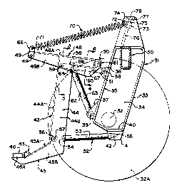
Turning now to Figures 2. 3 and 4 there is shown
an improved device for supporting the header on a frame. The
frame is again not shown in detail but includes a main
transverse beam 30 which is coupled to a wheel support strut 31
- 11 -
,.
~.C~~f0~32
which extends downwardly from the driver platform to support a
wheel hub 32 of a wheel 32A. The strut 31 is formed from a
fabricated tube including a back plate 33 and sides 34
extending at right angles to the back plate. From the front
face 35 is provided a pair of clevises 36 and 37 projecting
forwardly from the front face each defined by a pair of
parallel plates and each including a respective transverse
pivot pin 38 and 39. On the bottom wall 40 is attached a
further clevis 41 again formed from a pair of parallel plates
and a pin 42.
A header support member generally indicated at 43
includes a substantially vertical beam 44 and a bottom
forwardly extending support arm 45. The arm 45 extends
forwardly and downwardly and has a support 46 mounted at the
lower end for attachment to the header. The support 46
includes a rubber block 46A and a loop shaped bracket 47
through which a pin can be passed from the header to retain the
header on the resilient support 46. The header is thus cradled
on the support member 43. Support for an upper part of the
header to prevent twisting forwardly can be provided either by
a further connection to the bracket or by a separate center
link between the frame and the header.
The beam 44 is formed from a channel section with
- 12 -
~"'
a front web 44A and a rear open face. The bottom arm 45 is
similarly formed from a channel with an upper web 45A and a
downwardly facing open face. Side walls 45B of the bottom arm
are welded to side walls 44B of the channel to form a rigid
construction. The header support member 43 further includes an
upper arm 48 which projects from a forward end 49 positioned
forwardly from the beam 44 to a rearward end 50 spaced
approximately equidistant relative to the front from the web
44A. The upper arm 48 is again formed from a channel with a.
top web 48A and sides 48B. The channel has a width slightly
greater than that of the beam 44 so that the sides 48B as best
shown in Figure 3 extend along the outside of the beam 44 and
are welded thereto to form a rigid construction.
The header support member 43 is attached to the
strut 31 by an upper link generally indicated at 51 and by a
lower link generally indicated at 52. As shown in the prior
art. the lower link 52 is formed as a cylinder 53 and a piston
rod 54 with a suitable piston mounted within the cylinder and
operable to expand and retract by hydraulic couplings (not
shown). The rear end of the cylinder is attached by a rear
coupling 55 to the pin 42. The piston rod is attached by a
front coupling 56 to a pin 57 extending between the side walls
44B of the beam 44 adjacent the lower arm 45. The forward end
- 13 -
I~ ~ r'A
(_~ Pi td
of the piston rod and part of the cylinder can thus be received
within the channel and projecting through the open rear face of
the channel.
The sipper link 51 comprises a rigid lever 58
which is pivoted at its rear end to the pin 38 and at its
forward end to a pin 59 extending through the walls 44B and the
walls 48B of the header support member 43. The pin is held in
place as shown in Figure 3 by suitable split pins 60 so that it
can be removed and the lever 58 disconnected. Furthermore as
shown in Figure 3 the lever 58 is formed as a channel member
having an upper web 58A and depending wails 58B.
Between the web 58A of the lever and the
undersurface of the web 48A of the upper arm is provided a stop
member generally indicated at 61. The stop member is formed by
a plurality of shims which can be removed and increased or
decreased in thickness so as to provide an adjustment of the
stop member. As shown in Figure 2~ therefore. the stop member
limits the relative movement between the upper arm 48 and the
lever 58 in a clockwise direction. The lever 58 is
substantially wholly contained within the channel defining the
upper arm 48 so that the end 50 of the channel is closely
adjacent the clevis 36. This provides an attractive appearance
and provides a strong effective coupling between the upper link
- 14 -
6
51 and the upper part of the header support member 43.
A second cylinder and piston arrangement
generally indicated at 62 is positioned between the clevis 37
and the upper link 51. Thus the cylinder and piston
arrangement 62 includes a cylinder 63 and a piston rod 64. The
lower end of the cylinder is coupled to the pin 39. The upper
end of the piston rod 64 is coupled to a lever 65 by a clevis
coupling 66 at the top end of the piston rod. The lever 65 is
positioned within the channel defining the link 58 and is
pivotally coupled to the link 58 by a pin 67 extending across
the depending walls of the link. Thus the lever 65 defines a
lost motion connection between the piston rod 64 and the link
58. Actuation of the cylinder 63 to provide extension of the
piston rod thus pushes the link 58 upwardly in view of the fact
that the lever 65 and the clevis 66 are retained within the
channel defining the link 58. However the link 58 can lift
relative to the upper. end of the piston rod independantly due
to the pivotal action between the lever 65 and the link 58.
A bracket 68 is attached to the end 49 of the arm
48 by a pin 69. The bracket is formed by a pair of parallel
plates each connected on a respective side of the end 49 and
receives the end of a spring 70 in the form of a conventional
helical tension spring including looped ends 71 and 72. The
- 15 -
:: n .r
's, .~ l:Jy C . (-sf
end 71 passes through holes in the bracket 68. The end 72 is
coupled to a sliding coupling 73 and particularly to a pin 74
thereof. The sliding coupling 73 includes a threaded bore 75
which cooperates with a fixed threaded bolt 76 carried on a
support member 77 mounted upon an upper part of the vehicle
frame. The bolt 76 is inclined upwardly and rearwardly. The
bolt carries an upper head 78 by which the bolt can be rotated
to cause vertical movement of the sliding coupling 73.
In an alternative arrangement (not shown) the
forward portion of the arm 48 can be omitted and the spring
connected to the beam 44. In such a case, the connection of
the spring to the tractor must be moved rearwardly to allow a
sufficient length of spring to provide the required range of
movement.
In operation the header floats vertically under
force supplied by the float spring 70 by pivotal movement of
the top and bottom links about the pins 59, 38 and 57, 42
respectively. The adjustable shims 61 provide a stop member
that limits downward movement of the header support member 43
but allows the header and the header support member to float
upwardly if in engagement with an obstacle.
The header is raised by extension of the cylinder
52 which causes the vertical beam 44 and the top link 51 to act
- 16 -
~"".. ~ ~~ :'?
as one and to pivot about the pin 38. The stop member thus
holds the upper arm against further movement in the clockwise
direction so that the link and the beam must move together in
the lifting action' provided by the extension of the cylinder
53.
The springs 70 provide the floatation action and
can be adjusted by moving the coupling 73 in the required
direction to float various weights of headers over the desired
float range without the necessity of addition of further
springs or removal of any springs. This adjustment is
accomplished by simultaneously changing the distance between
the line of action of the spring and the effective pivot point
of the links 51~ 52 and by changing the spring length to change
the amount of spring pull by sliding the rear coupling 73.
For heavy headers the coupling 73 is moved
upwardly and away from the bracket so as to use the maximum
spring energy available. For light headers the coupling 73 is
moved downwardly and toward the bracket so as to give
substantially the same float range as the heavy header. In
practice the desired float range for small or lighter headers
is slightly greater than that of large headers. The
conventional technique explained above actually decreases the
float range for the lighter headers which is contrary to the
- 17 -
~U~a532
practical requirement.
It will be noted that the top link 51 is shorter
than the bottom link 52 and that the links are not parallel.
That is the spacing between the links increases so that it is
wider at a position adjacent the bracket than it is adjacent
the tractor. In view of this geometry that the links are not
parallel and are not of the same length, the distance from the
line of action of the spring to the actual effective pivot
point of the bracket (the intersection point of the two links
51 and 52) increases as the header is floated upwardly. Also,
in view of this geometry, the distance from the reaction of the
header mass on the bracket to the effective pivot point of the
bracket decreases as the header is floated upwardly. This
movement of the effective pivot point downwardly thus acts to
increase the moment arm to the line of action . _ -. of
the spring as the header moves upwardly. This increase in the
moment arm together with the reduction of the spring effect as
it becomes shorter and the reduction in the moment arm to the
header mass ensures that the proportion of the header mass
which is floated remains substantially constant over a desired
float range.
The cylinder 63 together with the compound link
arrangement 51. 65 provides the following features:
- 18 -
A
a) The cylinder 63 can be adjusted to set the
cut height. Thus the cylinder 63 is adjusted to and fixed at
the desired cutter bar height. Once the height of the cutter
bar of the header is set by actuation of the cylinder 63, the
cylinder 53 is operated to raise the header when required and
to lower it down to the preset height. The height of one end
of the header can be varied with respect to the other end of
the header by changing the length of the cylinder 63 on one
side relative to the other side.
b) There is a parallel header lift over the
cutting range, that is, the guard and draper angle of the
header are not significantly changed when the cylinder 63 is
operated as this cylinder operates on a substantially parallel
linkage.
c) The arrangement of the linkage allows a high
header lift. The lift range at the rear of the header is
limited because of interference between the front of the
operator's platform (not shown) and the header frame. However
by the arrangement of the linkage as shown, the lift range of
the header despite the limitation of the movement at the rear
of the header is sufficient to allow the guards to be raised
high to give good ground clearance.
Since various modifications can be made in my
- 19 -
6:
~l :'~ X ;:y
a 'ai '~ ~~ ~r l>,s
invention as hereinabove described and many apparently widely
different embodiments of same made within the spirit and scope
of the claims without departing from such spirit and scope. it
is intended that all matter contained in the accompanying
specification shall be interpreted as illustrative only and not
in a limiting sense.
- 20 -