Note: Descriptions are shown in the official language in which they were submitted.
METHOD FOR STERILIZING AN ENCLOSURÉ WITH
NoNcoNDENsING HYDROGEN PEROXIDE-CONTAINING GAS
Technical Field
This inven~ion relates to sterilization
systems and, in particular, to sterilization systems
that utilize yaseous hydrogen peroxide.
Backaround of the Invention
Hydrogen peroxide has long been used as an
antiseptic or disinfectant. However, hydrogen peroxide
is relatively unstable and decomposes rapidly.
Therefore, its widespread use has been hampered by the
difficulty of storing solutions of hydrogen peroxide.
Several processes for sterilizing articles
have utilized the technique of vaporizing the hydrogen
peroxide and introducing the vapor onto a surface to be
sterilized. The vapor is generally a multicomponent
admixture as the hydrogen peroxide is generally mixed
with water prior to vaporization.
In U.S. Patent No. 4,642,165 to Bier, hydrogen
peroxide (H202) mixed with water is vaporized and drawn
into a chamber by vacuum. Bier was attempting to
resolve the problem of the water vaporizing more readily
and in greater quantity than the hydrogen peroxide due
to the relatively low boiling point of the former. The
more ready vaporization of water caused the water vapor
to reach the object to be sterilized first and,
condensing thereon, preven ed the hydrogen peroxide
vapor from fully contacting the object. The
vaporization in Bier is done incrementally to ensure
that the relative amounts o~ peroxide and water vapor
present in the liquid are approximately maintained as
the vaporization proceeds so that both vapor components
reach the object to be sterilized at the same time. The
hydrogen peroxide solution is vaporized using a heating
3 ~
element. Control over other environmental factors
influencing the vapor formation and subsequent
condensation is not exerted. Bier utilizes a hydrogen
peroxide solution that is approximately twenty to fi~ty
percent by weight hydrogen peroxide. ~he pressure in
the sterilization chamb~r which draws in the vapor is
about 10 mmHg or less.
U.S. Patent No. 4,169,124 to Forstrom et al.,
teaches a cold gas sterilization process at a
temperature below 80C using a low concentration of
hydrogen peroxide (~75mg/L). Negative pressure is again
utilized to draw the vapor into the chamber, but the
reported pressure is preferably yreater than 15 inches
of Hg~ Sixty seconds to one hour is said to be
necessary to achieve the desired degree of sterility
using this process. According to this patent, it
requires six to twenty-four hours for the sporicidal
effect of this method to he realized.
U.S. Patent No. 4,424,189 to ~ick teaches
spraying hydrogen peroxide onto a heating element. The
formation of free oxygen resulting from flash
vaporization is taught as necessary to achieve an
antiseptic effect. The object to be sterilized is
wetted with the atomized hydrogen peroxide vapor.
None of the forgoing processes using hydrogen
peroxide vapor for sterilization achieves a high degree
of sporicidal effect in a relatively short amount of
time of the order of about 10 seconds or less. However,
the United States Food and Drug Administration (FDA) is
currently recommending that all medical and surgical
products be sterilized to a very low probability of
survival for spores, which are among the most difficult
microorganisms to kill. The recommended degree of kill
is that providing a sporicidal efficacy sufficient to
~5 assure a microbial survival probability of 106. That
is, to provide an assurance khat there is less than one
chance in one million that a viable microorganism is
present in the sterilized article or enclosure. This
sterility level can also be expressed as the negative
logarithm to base 10 of microorganism survival
probability, or "log10 kill." Thus, a survival
probability of 10 6 can also be concisely stated as 6
log1O ~cill.
For a general discussion of sterilization and
techniques therefor, see The United States Pharmacopeia
XXII, ch. 1211, pp. 1705 et seq., Atkinson et al.,
Biochemical Engineerina and Biotechnoloav Handbook,
Stockton Press, New York, N.Y. (1983), pp. 875 886, and
Demain et al., Manual o~ Industrial MicrobioloqY and
lS Biotechnoloc~y, American Society for Microbiology,
Washington, D.C. (19~6), pp. 345-362.
Summary of the Invention
The present method provides efficient
sterilization of an enclosure, or the contents thereof,
at a subatmospheric pressure in a matter of seconds, or
less. The specific conditions in the enclosure are
determined by the degree of spore kill desired.
Sterilization is achieved by maintaining a hydrogen
peroxide gas under non-condensing conditions. That is,
the sterilizing gas present i5 maintained above its dew
point temperature at the existing subatmospheric
pressure while ;n the enclosure to be sterilized.
The method of th~is invention contemplates use,
under subatmospheric pressure conditions, of a dry
hydrogen-peroxide containing gas, i~e., a moistureless
gas that will not condense upon introduction into the
enclosure to be sterilized. This enclosure is first
isolated from its surroundings and then evacuated to a
predetermined residual pressure. An aliquot of the dry
sterilizing gas is introduced into the enclosure and the
.
temperature therein is maintained at conditions which
ensure that condensation of the gas will not take place.
After sterilization ~o the desired degree, the hydrogen
peroxide gas is evacuated from the enclosure. The
enclosure is then sealed. An optional purging step,
using a sterile gas, can also be carried out if it is
desired to remove residuals from the enclosure prior to
sealing it.
The present process has the advantage of
achieving a high degree of sporicidal effect in a
relatively short amount of time. It only takes seconds,
or less, to sterilize a particular enclosure or the
contents thereo~. Th~s, rapid sterilization at fluid
filling line speeds can be readily achieved.
Brief Description of the Drawinas
FIGURE 1 is a schematic representation of the
present sterilization process;
FIGURE 2 is a perspective view of a connector
means for an enclosure to be sterilized as contemplated
by the present process;
FIGURE 3 is a sectional elevation view of the
connector shown in FIGURE 2 as connected to both a
sterilizing gas source and the enclosure to be
sterilized;
FIGURE 4 is a three-axis graphical
presentation illustrating the inter-relationship o~
sterilization process parameters for a desired spore
kill: and
FIGURE 5 is a graphical presentation
illustrating the inter-relationship among change in
residual pressure, temperature, and concentration of
hydrogen peroxide present in the introduced sterilizing
gas during the sterilization process.
æ~ed Descrip~ion o~ ~he Pre~erred EmbodimentS
The sterilization system for practicing the
m~ of this invention is schematically illuskrated in
~ E 1. Hydroyen peroxide source 16, vacuum source
.~" ~ærile purge gas source 18 and product source 19
mmmunicate with a common manifold equipped with a
~g means at 14 that controls access to the
re 10 to be sterilized via passageway 17. In
L~ es where the enclosure 10 has flexible walls that
m~ t~mLlapse when vacuum is drawn, vacuum source 12 also
(c~mm~cates with vacuum - energized gripper means 15
w.~ ~cuum line 13 which gripper means hold the walls of
~smre 10 open while vacuum is drawn. Heater means
:La ~n Dperative association with the temperature monitor5 ~.~ ~ provided to maintain the enclosure to be
ized at the desired temperature during the
ization process.
For sterilization purposes, the degree of
~m drawn, i.e., the residual pressure within the
~s~re to be sterilized, depends on the rate and
L~y of desired kill~ as well as on the
im~ration of hydrogen peroxide in the solution to be
~ed to generate the sterilizing gas, the
~E~ ture of that solution, and similar factors.
'.~e ~perating conditions are determined prior to
~r~ization of the enclosure and any items placed
~, and are monitored during sterilization.
ll~L~ the enclosure ~0 is evacuated to a residual
~e of no more than about 50 mmHg and, preferably,
3~ sidual pressure of no more than about 20 mmHg.
~re preferred residual pressure is about 15 mmHg.
~sidual pressure also provides a driving force for
~l;roduction of the sterilizing gas into the
~re to be sterilized as well as for expediting
J ~
purge cycles after sterilization as will be discussed in
detail hereinbelow.
When the desired residual pressure is
established in the enclosure 10, an aliquot of gaseous
hydrogen peroxide-containing sterilizing gas is
introduced into the enclosure 10 in a single step. This
is accomplished by use of a manifold valve means 14.
The proce~s can be automated by providing a multiport
valve at 14 which first provides fluid communication
between the vacuum source 12 and the enclosure 10,
enabling a vacuum to be drawn thereon. In the latter
case, when the desired residual pressure is reached, the
valve automatically turns, next providing fluid
communication between the enclosure 10 and the
sterilizing gas source 16. Prior to introduction into
the enclosure 10, the hydrogen peroxide-containing
sterilizing gas is above its dew puint temperature at
the existing pressure.
As the sterilizing gas is introduced into the
enclosure 10, pressure and temperature conditions are
maintained therein to ensure that no condensation of the
sterilizing gas tak2s place. To that end, enclosure 10
can be preheated, or the sterilizing gas may be
sufficiently superheated to provide the necessary heat
transfer to the enclosure 10. The sterilizing gas, and
thus the hydrogen peroxide gas constituent thereof,
remain above their respective dew point temperatures at
the existing pressure while in the enclosure 10. The
concentration of the hydrogen peroxide in the
sterilizing gas is sufficient to ensure that this gas is
sporicidal to a predetermined degree. If the heat
delivered by the steriliæing gas is insufficient to
maintain the temperature of the surfaces contacted by
the sterilizing gas in the enclosure above the dew point
temperatures, the enclosure, or an object placed therein
to be sterilized, can be heated during sterilization by
any suitable means, eOg., by radiant heat, by microwave
energy in the case of conductive materials, by
conductive heat transfer, or by similar expedients.
The concentration of hydrogen peroxide gas in
the introduced sterilizing yas can be in the range of
about 1.5 mg/l to about 150 mg/l, preferably about 5
mg/l to about 100 mg/l, depending upon the initial or
residual pressure in the enclosure 10 when the
sterilizing gas is introduced therein. At a relatively
higher residual pressure the time required to reach the
desired effective spore kill is longer.
A sterilization temperature range of 20C to
120C is selected to ensure that the gaseous hydrogen
peroxide/water admixture present remains gaseous within
the other parameters (i.e. t pressure, volume,
concentration) of the process. The term "dry", as used
herein and in the appended claims to characterize the
sterilizing gas, means that the sterilizing gas is
moistureless and mist-free. The sterilizing gas may
contain non-condensable water vapor, however.
The enclosure 10 to be sterilized, and any
contents thereof are heated to approximately the same
temperature as the sterilizing gas to avoid condensation
of the gas on cooler surfaces. Obviously, the higher
the temperature, the less likely the gas will condense
assuming all other parameters remain constant. When the
sterilization temperature ls within the temperatuxe
range of 20CC to 120C, residual pressure is a more
significant parameter than time, as will be discussed in
greater detail hereinbelow.
The dry sterilizing gas is held within the
enclosure 10 for a time period sufficient to effect the
desired degree of kill of spores or other bacteria that
might be present therein. As spores are the hardiest of
.~
the microorganisms that might be present in the
enclosure 10, the killiny o~ a significant portion of
the spore population results in the kill of essentially
all other microorganisms as well. The time ~or which
the hydrogen peroxide sterilizing gas is held in the
enclosure 10 în the presence of the microorganisms to be
eradicated can vary. To achieve 6 log10 kill the time
is genexally less than about one second, and can be as
short as a fraction thereof. The specific time in which
the desired degree of spore kill is achieve~ is
dependent upon the process parameters (i.e.,
temperature, pressure, concentration), but is relatively
short. Using the parameters at which the hydrogen
peroxide is at its dew point temperature as point zero,
the greater the deviation of these parameters above
point zero, the less the time necessary to achieve the
desired degree of kill. For a lower degree of kill,
e.g.~ 5 log10 kill, milder conditions are sufficient,
but noncondensing conditions must be maintained. At the
preferred steriliæation temperatures and pressures, once
the desired conditions are reached within the enclosure
to be sterilized, the sterilization itself takes place
virtually instantaneously, and processing time becomes
primarily a function of available process equipment.
After the desired degree of spore kill, valve
14 allows the now sterilized enclosure to be purged, if
desired, of any remaining hydrogen peroxide gas and any
residuals resulting from the antimicrobial action of
that gas.
This purge can be accomplished by first
removing the gas present in the enclosure using the
vacuum source 12. Next, a sterile purge gas can be
introduced. Once sufficient purge gas has been
- introduced into enclosure 10, a vacuum is again drawn on
the enclosure, removing the purg~ gas and residuals from
the sterilized enclosure. This step can be repeated if
necessary, or desired, to proYide several evacuation and
flushing cycles.
Whether or not a purge step ls required
depends upon the en~ use to which the sterilized
enclosure is to be put. Only if removal of hydrogen
peroxide residuals is desired is an evacuation-and-flush
purge cycle necessary. The exact number of evacuation-
and-flushing cycles to be used in any particular
application is determined to a large extent by th~
volume of the sterilized enclosure as well as by the
intended end use of the sterilized container. The
larger the volume the greater the number of evacuation-
and-flushing cycles needed for the removal of residual
material from the sterilization process. If the
enclosure 10 is to be filled after sterilization with an
intravenous fluid or with a dialysate for peritoneal
dialysis, four to five such cycles are preferred.
The extent of evacuation using the vacuum
source 12 during any given cycle is also a factor in
determining the nu~ber of evacuation and flushing
cycles. Evacuation of the enclosure 10 during any cycle
is to a residual pressure of no more than about 50 mmHg.
The number of evacuation and-flushing cycles, in any
given instance, can be reduced by evacuation to a
relatively lower residual pressure of about 20 mmHg, or
lower, for example.
Following either the evacuation of the
sterilizing gas from the enclosure 10 or the optional
~vacuation and flushing cycle or cycles, the sterilized
enclosure 10 is filled with the desired flowable
material contents which can be a fluid or a solid,
particulate or otherwise, and then sealed prior to
disconnecting the sterilization system from the
enclosure. Sealing can be accomplished by either heat
~ 7 Ih~ ~
sealing the enclosure or by any other appropriate method
which provides a hermetic ~eal, such as ultrasonic
bonding or the like. Alternatively, i~ the use for the
sterilized enclosure is intended to be that of a
container for specimens, the sterilized container is
sealed from its surroundings immediately after
sterilization and again prior to disconnecting the
sterilization system from the enclosure. Similarly, if
the sterilized enclosure 10 is an antechamber or a
connector for a container to be filled, it can be
sterilized before further operations are undertaken.
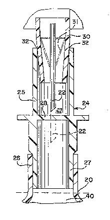
A connector 24, illustrated in FIGURES 2 and
3, is provided for facilitating the practice of this
invention. Connector 24 is a hollow tube that defines a
confined fluid flow communication passageway between the
various systems for vacuum, sterilization gas, purge gas
and fill and ~he enclosure to be sterilized 10. The
connector 24 has an open end ~5 that defines an access
cavity, a septum 28 at an intermediate position within
the hollow tube and which is pierceable by a nozzle 22
(FIGURE 3) which, in turn, connects the container 40
with the sterilization apparatus, and dispensing end 27.
The connector 24 is permanently attached to container 40
about dispensing end 27 isolating the connector 24 and
container 40 from the atmosphere.
FIGURE 3 illustrates use of the connector 24
when secured in a gas-tight manner to the inlet 26 of
the container 40 which can be a sterile container or a
container to be sterilized. A seal is formed at 32 when
the distal, taper~d end of mandrel 30 with the nozzle 22
therein mates with or is removably received within open
end 25 of the connector 24 isolating the connector 24
and bag-type container 40 from the environment. The
- pierceable septum 28 of connector 24 is shown penetrated
by the nozzle 22 in phantom which in turn, communicates
'...',: ~
.. . .
~ 3~
with a vacuum source such as 12, sterilization gas
source such as 16, and purge gas source such as 1~. The
nozzle also provides fluid communication for the
enclosure 40 with a product source such as lg, if it is
desired to fill the container 40 as well.
A flexible membrane 31 forms a seal between
the exterior portion of nozzle ~2 and the interior
portion of the distal, tapered end of mandrel 30 to
ensure no access to the container 40 other than through
nozzle 22. The membrane 31 is sufficiently flexible so
that the seal is maintained even when the nozzle is in
its fully extended position.
A sterilization antechamber 29 is defined by
mandrel 30 in cooperation with connector open end 25
when the distal, tapered end of mandrel 30 is received
therewithin as shown in FIGURE 3. The tapered periphery
of mandrsl 30 engages the distal end portion of open end
25 to provide a seal 32. Initially nozzle 22 i5
positioned above septum 28 while antechamber 29 is
sterilized as described hereinabove. Antechamber 29 can
be sterilized, along with that portion of nozzle 22 that
is situated within antechamber 29, with or without
subsequent evacuation-and-~lush purge cycles, as
required-for the contemplated filling operation for
container 40.
If the container 40 has been presterilized,
next the sterilized portion of nozzle 22 pierces septum
28, container 40 is ~illed with the desired contents,
and thereafter sealed at about plane 20 to ensure
continued sterility of the container and its contents.
Thereafter nozzlP 22 and mandrel 30 are separated from
connector 24 and positioned for a subsequent
sterilization and filling procedure.
3 ~
12
Sealing of the container 40 at about plane 20
can be effected in any convenient manner as discussed
hereinabove with reference to enclosure 10.
On the other hand, if container 40 has not
been presterilized, it can be now sterilized by first
penetrating septum 28 with nozzle 22 and then repeating
the sterilization procedure carried out ~or the
antechamber 29. The sterilization conditions and the
purge cycles can be the same or different, depending
upon the relative volumes of the antechamber 29 and the
container 40.
The sterilization of antechamber 29 can be
optional if container 40 has not been presterilized, if
the pierced septum 28 provides an adequate seal with
nozzle 22, because in such a case the interior of
container 40 and the intrudiny portion of nozzle 22 are
sterilized simultaneously as container 40 is sterilized.
The present sterilization method permits the
utilization of aqueous hydrogen peroxide solutions
containing a relatively high concentration of hydrogen
peroxide. Hydrogen peroxide solutions with up to 70
- weight percent of hydrogen peroxide can be used in the
method disclosed herein. Higher hydrogen peroxide
concentrations are undesirable from the standpoint of
safety or oxidizing propensity. Highly concentrated
agueous hydrogen peroxide solutions may cause flesh
burns upon contact with the skin or the eyes or vapor
inhalation, and also may oxidize surfaces in contact
therewith.
For purposes o this invention, aqueous
solutions having a hydrogen peroxide concentration in
the range of about 40 weight percent to about 60 weight
percent are praferred. Particularly preferred are
agueous solutions containing about 50 weight percent of
hydrogen peroxide.
~::,J ~ "~ ~5 ~;
,
13
The present process i~ well ~uited for the
sterilization not only of containers destined for a
sterile filling operation but also for sterilization of
relatively large enclosures such as lyophilization
chambers, or the like, connectors on previously filled
containers such as dialysate bags for continuous
ambulatory peritoneal dialysis, bags containing
intravenous fluids, or the like, as well as medical
instruments, kit and like devices. If the enclosure to
be sterilized is a flexible bag, vacuum can be applied
to the outside of the bag to keep the bag from
collapsing during each evacuation step.
The inter-relationship of residual pressure
change and sterilization time for a desired degree of
Bacillus subtilis niaer spore kill when using a 50-
weight percent aqueous hydrogen peroxide solution in the
process of the present invention is shown in FIGU~E 4.
It will be seen that the sterilization time is a
relatively minor factor vis-a-vis the degree of kill,
and that the target degree o~ kill can be readily
monitored during a sterilization procedure by noting the
change in residual pressure as an aliquot of the
sterilizing gas is introduced into the enclosure to be
sterilized. The mathematical correlation for the
graphical presentation depicted in FIGURE 4 is
log10 kill = 715.833647 ~p + 0.72408 log10 t - 0.39996
Where ap denotes the change in residual pressure, in
atmospheres, upon addition of 50-weight percent aqueous
hydrogen peroxide solution and t denotes the time, in
seconds, the enclosure or product to be sterilized is
exposed to the sterilizing gas.
FIGURE 5 illustrates the interrelationship
between change in the aforementioned residual pressure
on one hand and temperature as well as hydrogen peroxide
concentration in the introduced sterilizing gas on the
:
o
14
other. For the graphical presentation of FIGURE 5 the
mathematical correlation is
~P = 4.8 X 10 S TZ + 2,422867 X 10 10 T4 _ 0.214183 CH 0 f
+ 2 . 52593
Where ~p is as defined hereinabove with respect to
FIGURE 4, T is temperature expressed in degrees Kelvin,
and CH202 i5 the concentration of hydrogen peroxide in a
H202/H20 solution, expressed as weight percent based on
total weight of the solution.
lo The above discussion is intended by way of
example only and is not intended to limit the invention
in any way except in the spirit and scope of the
appended claims.