Note: Descriptions are shown in the official language in which they were submitted.
; 2~0597
CARRIER STOCK WITH TEAR-OPEN TABS
Technical Field of the Invention
This invention pertains to carrier stock for
machine application to substantially identical
containers. This invention pertains, more particularly,
to carrier stock that is severable to form individual
carriers with separate apertures to receive the
individual containers. Tear-open tabs are provided,
which enable the containers to be easily removed.
Backqround of the Invention
Typically, carrier stock with individual
container-receiving apertures for machine application to
substantially identical containers is formed, as by die-
cutting, from a single sheet of resilient polymeric
material, such as low density polyethylene. An example
of such carrier stock is disclosed in Weaver et al. U.S.
Patent No. 4,219,117.
Yarious attempts have been made to provide
such carrier stock with tear-open capability. An
example of particular interest is disclosed in Olsen
U.S. Patent No. 4,064,989.
As disclosed in Olsen U.S. Patent No.
4,064,989, outer band segments of such carrier stock are
formed with tear-open tabs, which extend from outer band
segments. A slit, which is associated with each tab,
extends at an acute angle to a line drawn to a base of
such tab. An arrow is impressed on each tab so as to
indicate, to a user, in which direction to pull such tab
so as to sever the outer segment formed with such tab.
In actual experience with such stock, it has been found
that if the user pulls in a wrong direction there is
some risk of failure due to a tab being torn away
without the outer segment being torn through, or due to
the outer segment exhibiting excessive resistance to
being torn through.
~40~7
A recent example of an attempt to provide
carrier stock with tear-open capability is disclosed in
Gordon U.S. Patent No. 4,925,020. Older examples are
disclosed in Poupitch U.S. Patent No. 2,997,169, Rapata
U.S. Patent No. 3,038,602, Poupitch U.S. Patent No.
3,~86,651, Owen U.S. Patent No. 3,504,790, and Braun et
al. U.S. Patent No. 3,721,337.
There has remained a need, to which this
invention is addressed, for improved carrier stock with
L0 tear-open capability.
Summarv of the Invention
This invention provides carrier stock formed
from a single sheet of resilient polymeric material,
such as low density polyethylene, for machine
application to substantially identical containers. Such
stock is severable to form individual carriers, which
are configured to include tear-open tabs enabling the
containers to be easily removed. Each individual
carrier has separate apertures to receive the individual
containers. Preferably, the separate apertures are
arranged in two longitudinal rows.
The stock is formed for each individual
carrier with integrally joined band segments defining
the separate apertures. The band segments include outer
segments extending generally in a longitudinal direction
when the stock is unstressed.
Each outer segment is formed with a tear-open
tab extending in a generally transverse direction when
the stock is unstressed. It is preferred that ea~h tab
extends into one of the separate apertures when the
stock is unstressed. Moreover, it is a characteristic
feature of this invention that each tab is slitted so as
to define a series of frangible bridges, as described
below.
A first slit of each tab extends in a
generally longitudinal direction when the stock is
- - 2040597 --
- 3 -
unstressed. Preferably, the first slit of each tab has
an open end at the outer edge of such tab and a closed
end. Alternatively, the first slit of each tab has one
end adjacent to but spaced from the outer edge of such
tab so as to define a frangible bridge between such end
of the first slit and the outer edge of such tab.
A second slit of each tab extends in a
generally transverse direction when the carrier stock is
unstressed. Preferably, the second slit is spaced from
the first slit so that a frangible bridge is defined
between the first and second slits. Alternatively, the
first and second slits may be sections of a continuous
slit, which may comprise a curved slit connecting the
first and second slits.
It is a preferred feature that the first and
second slits of each tab are arranged so that an
imaginary line extending in a generally longitudinally
direction from the first slit of such tab intersects the
second slit of such tab. Thus, a portion of the second
slit extends on each side of the imaginary line, when
said stock is unstressed.
In a preferred arrangement, each outer segment
is slitted so as to define third and fourth slits, as
described below. In considering the third and fourth
slits, it is convenient to refer to each outer segment
as having first and second edges with the first edge
merging with the outer edge of the tab extending from
such outer segment.
Each of the third and fourth slits extends in
a generally longitudinal direction when the stock is
unstressed. The third and fourth slits of each outer
segment are arranged so that a frangible bridge is
defined between such third slit and the second slit of
the tab extPn~ing from such outer segment, so that a
frangible bridge is defined between such third and
fourth slits, and so that a frangible bridge is defined
i
2040597
-
between such fourth slit and the second edge of such
outer segment.
The slits associated with each tab are
arranged so that the outer segments are not weakened
significantly but so that the frangible bridges can be
easily torn by a user pulling on such tab, whereby the
- outer segment formed with such tab can be easily severed
to release a container from the aperture bounded partly
by such outer segment. There is minimum risk of failure
due to such outer segment breaking in application
machinery, or due to such tab being torn away without
tearing through such outer segment. At least in the
preferred arrangement, there is minimal risk of failure
due to such outer segment exhibiting excessive
lS resistance to being torn through.
Herein, references to slits in the carrier
stock are intended to refer to scorings, or lines that
are not cut entirely through the carrier stock, as well
as to those that are cut entirely through the carrier
stock and to slits defined by plural perforations.
These and other objects, features, and
advantages of this invention are evident from the
following description of certain embodiments of this
invention, with reference to the accompanying drawings.
Brief Description of the Drawinqs
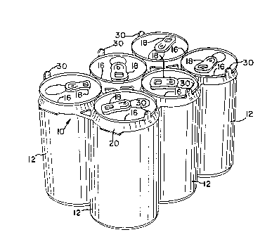
Figure 1 is a perspective view of a package
comprising six identical containers and a carrier, which
is severed from carrier stock according to this
invention.
Figure 2 is a plan view of a carrier severed
from carrier stock according to a preferred embodiment
of this invention.
Figure 3 is an enlarged, fragmentary detail
showing a representative one of a plurality of tear-open
tabs characteristic of the carrier stock, as shown in
Figure 2; appearing with Figure 1.
` ~ ~ 5 ~ 2040597
Figure 4 is an analogous, fragmentary detail
showing a tear-open tab characteristic of carrier stock
according to an alternate embodiment of this invention;
appearing with Figure 1.
Figure 5 is an analogous, fragmentary detail
showing a tear-open tab characteristic of carrier stock
according to a simplified embodiment of this invention;
appearing with Figure 1.
Figure 6 is an analogous, fragmentary detail
showing a tear-open tab characteristic of carrier stock
according to a Purther embodiment of this invention;
appearing with Figure 1.
Detailed Description of the Illustrated Embodiments
As shown in Figures 1 and 2, carrier stock 10
for machine application to substantially identical
containers 12 constitutes a preferred embodiment of this
invention. Such stock 10 is formed with separate
apertures 14 to receive the individual containers 12.
The carrier stock 10 is severable along transverse lines
L, to form individual carriers 20 (one shown) that are
substantially identical.
As shown in Figure 1, the containers 12 are
beverage cans of a type used commonly for beer, soft
drinks, and other beverages. Also, each container 12
has a chime 16 at one end, which is provided with a pull
tab 18. This invention is not limited, however, to
usage with such cans but is useful with cans, bottles,
and other containers of various types.
In Figure 1, a package is shown, which
comprises six such containers 12 and one such carrier
20, as severed from such stock 10. While the carrier 20
is shown to be directly adjacent the chimes 16, this
invention is not limited to this location on the
containers 12. This invention contemplates that the
carrier 20 may be positioned downwardly on the side
walls of such containers. In Figure 2, one such carrier
20 is shown in an unstressed condition.
The carrier stock 10 is formed in an
indeterminate length, as by die-cutting, from a single
29~û5~7
sheet of resilient polymeric material. A preferred
material is low density polyethylene. A preferred
thickness for such stock 10 in an unstressed condition,
if low density polyethylene is used, is about 16 mils.
The carrier stock 10 is formed, for each
individual carrier 20, with integrally joined band
segments defining six separate apertures 14. As shown
in Figure 2, such apertures are in a rectangular array
with longitudinal rows and transverse ranks, namely two
longitudinal rows and three transverse ranks. The band
segments include outer segments 22 extending in a
generally longitudinal direction when such stock 10 is
unstressed.
It is a characteristic feature of the
preferred embodiment shown in Figures 1, 2, and 3 that
each tab 30 is slitted so as to define first and second
slits described below.
Each outer segment 22 is formed with a tear-
open tab 30 extending in a generally transverse
direction when the carrier stock lO is unstressed. Such
tab 30 extends from a midportion of such outer segment
22. Preferably, as shown, each tab 30 extends inwardly,
into one of the separate apertures 14, when such stock
10 is unstressed. Alternatively, however, each tab 30
may extend outwardly when such stock 10 is unstressed.
The first slit 32 of each tab 30 extends in a
generally longitudinal direction when the carrier stock
is unstressed. Such slit 32 has an open end 34 at an
outer edge 36 of such tab 30, as shown, and a closed end
38.
The second slit 40 of each tab 30 extends in a
generally transverse direction when the carrier stock 10
is unstressed. The second slit 40 is spaced from the
first slit 32 so as to define a frangible bridge 42
between the first and second slits.
- 2~4059~
The first and second slits of each tab 30 are
arranged so that an imaginary line extending in a
generally longitudinal direction from the first slit 32
intersects the second slit 40. Thus, as shown, a
portion of the second slit 40 extends on each side of
the imaginary line when the carrier stock 10 is
unstressed. Consequently, as the frangible bridge 42 is
torn by a user pulling on such tab 30, there is minimal
risk that part of such tab 30 will be torn away from the
remainder of such tab 30 or that such tab 30 will be
torn away from the outer segment 22 formed with such tab
30. Continued pulling force will be directed
substantially transversely of the outer segment 22 as a
result of the orientation of the second slit 40.
Since the band segments including the outer
segments 22 are tensioned by application machinery (not
shown) when the carrier stock 10 is applied to the
containers 12, it is important that the second slit 40
of each tab 30 does not weaken the outer segment 22
formed with such tab 30. Thus, the second slit 40 of
each tab 30 extends approximately to but not
substantially beyond an imaginary line where such tab 30
merges with the outer segment 22 formed with such tab
30, and along which such tab 30 tends to fold, as shown
in Figure 1, when the carrier stock 10 is applied to the
containers 12.
It is a characteristic feature of the
preferred embodiment shown in Figures 1, 2, and 3 that,
in a region near each tab 30, each outer segment 22 is
slitted to define third and fourth slits described
below.
In considering the third and fourth slits, it
is convenient to refer to each outer segment 22 as
having a first or inner edge 44 divided into separate
portions, one on each side of the tab 30 extending from
such segment 22, and as having a second or outer edge
-- 2040597
46. The first or inner edge 44 merges with the outer
edge 36 of such tab 30 and tends to coincide with an
imaginary line along which such tab 30 tends to fold, as
shown in Figure 1, upon machine application of the
carrier stock 10 to the aforementioned containers.
Each of the third and fourth slits of each
outer segment 22 extends in a generally longitudinal
direction when the carrier stock 10 is unstressed.
Consequently, such segment 22 is not weakened
substantially by its third and fourth slits and does not
tend to break when tensioned by application machinery
(not shown) used for machine application of the carrier
stock 10 to the aforementioned containers 12.
In each outer segment 22, the third slit 50 is
closer to the first or inner edge 44 of such segment 22,
and the fourth slit 52 is closer to its second or outer
edge 46. Moreover, the third and fourth slits are
arranged so that an imaginary line extending in a
generally transverse direction from the second slit 40
of the tab 30 extending from such segment 22 when the
carrier stock 22 is unstressed intersects the third slit
50, approximately at a right angle, as shown, but does
not intersect the fourth slit 52. As shown, the first
slit 32 of such tab 30 and the fourth slit 52 of such
segment 22 are on opposite sides of the imaginary line
mentioned in the preceding sentence.
The third and fourth slits of each outer
segment 22 are arranged so as to define a frangible
bridge 54 between the third slit 50 of such outer
segment 22 and the second slit 40 of the tab 30
extending from such outer segment 22, a frangible bridge
56 between such third and fourth slits, and a frangible
bridge 58 between the fourth slit 52 of such outer
segment 22 and the second or outer edge 46 of such outer
segment 22. The frangible bridges defined by the first,
`~- 2~40597
second, third and fourth slits are arranged in- a
longitudinally staggered series, as shown.
Elements similar to elements designated by
unprimed reference numbers in Figures 1, 2, and 3 are
designated by primed reference numbers in Figure 4, by
double-primed reference numbers in Figure 5, and by
triple-primed reference numbers in Figure 6.
The alternate embodiment shown in Figure 4 is
similar to the preferred embodiment shown in Figures 1,
2, and 3 except that the first slit 32' of each tab 30'
extending from each outer segment 22' is closed at each
of its ends 34', 38', and is spaced from the outer edge
36' of such tab 30' so as to define a frangible bridge
60' between the end 34' closer to such edge 36' and the
first slit 32'. The second slit 40' of each tab 30' is
similar to the second slit 40 of each tab 30. The third
slit 50' of each outer segment 22' is similar to the
third slit 50 of each outer segment 22. The fourth slit
52' of each outer segment 22' is similar to the fourth
slit 52 of each outer segment 22.
The simplified embodiment shown in Figure 5 is
similar to the preferred embodiment shown in Figures 1,
2, and 3 except that the third and fourth slits are
omitted. The first slit 32" of each tab 30" extending
from each outer segment 22" is similar to the first slit
32 of each tab 30. The second slit 40" of each tab 30
is similar to the second slit 40 of each tab 30. As a
possible modification (not shown) the first and second
slits may be similar to the first and second slits of
the alternate embodiment shown in Figure 4 and described
above.
A simplified embodiment (not shown) is
contemplated that is similar to the preferred embodiment
shown in Figures 1, 2, and 3 except that the fourth
slits are omitted. The first, second, and third slits
are similar to the first, second, and third slits of the
- .~G~0~7
-- 10 -
preferred embodiment shown in Figures 1, 2, and 3 or to
the first, second, and third slits of the alternate
embodiment shown in Figure 4. As a possible
modification (not shown) the third slits may be centered
between the inner and outer edges of the outer segments.
The further embodiment shown in Figure 6 is
similar to the alternate embodiment shown in Figure 4
except that the first and second slits of each tab 30' "
are sections of a continuous slit. As shown in Figure
6, the first and second slits of each tab 30 " ' are
connected by a curved, substantially arcuate section
62''' of the continuous slit. The curved section 62 " '
extends between one end 38''' of the first slit 32 " '
and one end 64 " ' of the second slit 40'''. A frangible
bridge 60''' is defined between the other end 34 " ' of
the first slit 32 " ' and the outer edge 36' " of such
tab 30'''. The second slit 40''' extends approximately
to but not substantially beyond an imaginary line where
such tab 30''' merges with the outer segment 22 " '
formed with such tab 30 " '. The third slit 50' " of
each outer segment 22' " is similar to the third slit 50
of each outer segment 22. The fourth slit ~2 " ' of each
outer segment 22 " ' is similar to the fourth slit 52 of
each outer segment 22.
In the further embodiment shown in Figure 4,
tear-away force exerted by a user on each tab 30 " ' will
be first directed parallel to the longitudinal direction
of the carrier stock and, then, continuously directed
perpendicularly, in a transverse direction relative to
such stock, so as to insure that rupture occurs across
the outer segment 22 " ' formed with such tab 30 " '
rather than across such tab 30 "'.
In each of the illustrated and contemplated
embodiments, the slits are arranged so that the outer
segments are not weakened substantially, but so that the
frangible bridges can be easily torn by a user pulling
204(~59~
-- 11 --
on the tear-open tabs. The outer segments can be easily
severed so as to release the containers from the
apertures bounded partly by the outer segments.
In each of the illustrated and contemplated
embodiments, there is minimal risk of failure due to any
outer segment breaking in application machinery used to
apply the carrier stock to the containers. Moreover,
there is minimal risk of failure due to any tear-open
tab being torn away without the associated outer segment
being torn through.
In the preferred embodiment, and in the
contemplated embodiments including third slits but not
fourth slits, there is minimal risk of failure due to
any outer segment exhibiting excessive resistance to
being torn through.
Various other modifications may be made
without departing from the scope and spirit of this
invention.