Note: Descriptions are shown in the official language in which they were submitted.
2 ~
BATCH TEST APPARATUS WITH ADJACENT
NEGATIVE CONTROL AND PATIENT SAMPLE ROWS
FIELD OF THE INVENTION
The invention concerns test apparatus, a
kit, and method for doing immunoassays, using
positive and negative controls and a visual
comparison of the patient sample Iesult against the
result of the negative control.
BACKGROUND OF THE INVENTION
Many test devices have been provided for
conducting immunoassays. In some instances the
device is personalized to test only 1 patient sample,
a positive control and a negative control, using
three test wells as shown for example in U.S. Patent
~ No. 4,847,199, and in commonly-owned U.S. Serial No.
240,17~ filed on September 6, 1988 by Hinckley et al,
entitled ~Sliding Valve for Vent of Liquid Collecting
Compartments", now allowed.
In such devices, the negative control serves
two functions - to show what background color, if
any, can be expected without the targeted antigen
being present, and to act as a control in the event
the reagents should become damaged, e.g., denatured
(?) to the point that a~ sample will cause a color
to form whether or not the targeted antigen is
present. As is well known, such devices are read by
visually comparing color changes. Such devices are
limited in that multiple patient testing i8 not
possible in any one device.
Still other test apparatus has provided for
batch testing of many samples, as well as for a
positive control and a negative control. Examples
are shown in U.S. Patent No. 4,245,043 and EPO
-2- 2 ~
Publication 177,352, wherein test wells are arranged
in rows and columns, and a row for example will be
dedicated to being all a positive control, all a
negative control, or a batch of patient samples.
Thus, in the apparatus of U.S. Patent No. 4,245,043,
rows A and K are strictly for negative controls, that
is, produce no substantial color change, rows B and J
are for positive controls and produce a substantial
color change, and the intermediate rows C-I are for
test samples (column 5, lines 53-60). Similarly, in
EP0 Publication 177,352, column 12 is reserved for
the "blank" (a negative control producing
substantially no color change) whereas column 11 is
for the positive control (labeled "standard~). All
the columns prior to column 11 are for samples.
It will be apparent that the batch testing
apparatus of the above-noted publications have one
thing in common - the row or column of test wells
that produces no substantial color change has
interposed between it and the rows or columns of test
sample wells, a row or column, respectively, that
always produces a substantial color change (the
positive control). This arrangement has a
substantial disadvantage, and that is, that the user
is unable to visually compare a negative control test
well (mostly colorless) directly with a test sample
well, without having to look at an intermediate wel~
between them that h~ a substantial color change.
This is particularly troublesome when a patient
sample well produces a color change that is only
slightly more than the negative well, but not nearly
as much as the positive well positioned between it
and the negative well. In such a case, the positive
well color change is so great as to make difficult,
if not impossible, a determination as to whether the
patient sample is in fact enough greater in color
2 ~
-3-
change than the negative control, to count as a
"positive". Thi~ problem is f~rther compounded, as
in the Case of the European publication noted above,
when test sample wells farthest away from the
negative control well, have to be compared while
visually skipping over the other tes~ ~a~ple wells in
the same row that may have a greater color change
than the one in question. Even if not all of the
intervening test wells are used, the mere fact of
their location between the wells to be examined,
creates difficulties.
All these problems can lead to substantial
error in estimating if a particular test sample well
is in fact a "positive" rather than a ~negative~
result.
It has been a problem, therefore, prior to
this invention, to provide a batch testing apparatus
wherein the patient or test sample wells are all
easily and accurately contrasted by eye with the
negative wells, to determine if the results are not
negative.
~ X_QF_~ INV~NTI0~
We have constructed test apparatus that
solves the aforementioned problems.
More particularly, in accord with one aspect
of the invention there is provided test apparatus for
conducting immunoassa~s, said apparatus comprising a
test membrane constructed to receive a liquid, each
of the wells being positioned to form at least two
rows with at least two of the wells in each row, at
least some of the wells being constructed and
designated to receive a negative control liquid and
the remainder of the wells being constructed and
designated to receive either a positive control
liquid or a patient sample liquid. The apparatus is
improved in that the at least some wells form a
portion of a row and the remainder wells form a
portion of a row located adjacent to the portion of a
row of the at least some wells with no well from the
remainder wells being positioned in between the
remainder wells and the corresponding adjacent at
least some wells of the portion of a row, so that a
user can readily compare the results in the well of
one row against the results in a well of the other
row.
In accord with yet another aspect of the
invention, there is provided a test kit for
conducting immunoassays, comprising a frame and a
plurality of housings removably mounted in said
frame, each of said housings having a plurality of
test wells each comprising a test membrane
constructed to receive a liquid, each of the wells
being positioned to form at least two rows with at
least two of the wells in each row, the wells of one
of the rows being constructed and designated to
receive only materials for negative control and the
wells of the other row being constructed as
color-producing wells that are designated to receive
only either materials for positive control or patient
sample, such that no color-producing well is
positioned between a well for patient sample liquid
and a negative control well.
In accord with still another aspect of the
invention, there is provided a method for conducting
an immunoassay for a targeted antigen or antibody in
a plurality of patient samples, using a plurality of
test wells and a positive and negative control, the
controls comprising the reagents which, if properly
combined and maintained in active for~, will always
form a substantial color change in the case of the
positive control and never form a substantial color
change in the case of the negative control in the
absence of the sought-for antigen or antibody. The
method comprises the steps of:
a) arranging the test wells into two rows,
each well in a row being adjacent to a well of the
other row;
b) depositing into one of the rows, only
the materials of the negative control in the proper
sequence that produces no substantial color change;
c) depositing into the respective wells of
the other of the rows, either the patient samples or
some of a positive control, and the reagents
necessary to test for a targeted antigen or antibody;
and
d) comparing the lack of a substantial
color change in the wells of the one row with the
presence or absence of a substantial color change in
a well of the other row adjacent thereto, to
determine, respectively, that the targeted antigen or
antibody is present or absent in the patient sample
wells.
Accordingly, it is an advantageous feature
of the invention that a batch test apparatus is
provided wherein a test sample well is readily and
accurately visually compared against a negative
control well, because there is no well between them
having a substantial color change.
It is another advantageous feature of the
invention that such test apparatus can be constructed
of variable length, as needed.
Other advantageous features will become
apparent upon reference to the following Detailed
Description of the Preferred Embodiments, when read
in light of the attached drawings.
BRIEF DESCRIPTION OF TH~ DRAWINGS
Figure 1 is an exploded perspective view of
a test apparatus constructed in accordance with the
invention;
.. 2 ~ 3 ~ l3
~5--
Figure 2 is a frame for mounting the
housings that provide the test apparatus of Figure l;
Figures 3 and 4 are each a plan view of the
apparatus of Figure l, illu~trating its use;
Figure 5 is a plan view similar to that of
Figure 3, but of an alternate embodiment; and
Figure 6 is a plan view similar to that of
Figure 4, but illustrating another embodiment.
DESCRIPTION OF T~L~LL~ L~L~L~ L
The invention is hereinafter described by
reference to plural housings, each of which has only
three test wells, that together provide two rows of
nine wells each, to test for chlamydia using one of
two preferred immunoassays. In addition, the
invention is useful re~ardless of how many wells is
provided in a single housing, of how many wells is
provided in a single row, and regardless of the
antigen being tested or the protocol used.
As noted, the assay is preferably for
~O chlamydia, which as is conventional requires the
extraction of the antigen from a patient's
genital/urinary tract sample. This i8 done by
conventional extraction techniques, omitted here.
Two alternate immunoassay techniques are used, after
~5 the antigen is deposited onto a suitable filter
membrane. In one, a monoclonal antibody (MAb~
specific to the chlamydia antigen is added to the
membrane, where it complexes with the antigen, if
present, and otherwise passes through the membrane.
Thereafter, a labeled antibody to that antibody is
added which will complex with the first MAb (if
present), and otherwise it will pass through the
membrane. In the other, and more preferred,
techni~ue, the MAb is preincorporated with a label,
so that no second antibody need be added. In either
case, the label is preferably horse radish peroxidase
-7-
(HRP). Thereafter (in either case), a dye solution
is added, which contains at least a leuco dye and
hydro~en peroxide, as is conventional. In the
presence of the HRP, the hydrogen peroxide will
convert the leuco dye into dye, the concentration and
color of which is proportional to the amount of
antigen present.
The assay uses positive and negative
controls. As is conventional, the positive control
is a pre-prepared solution of chemically inactivated
chlamydia elementary bodies that will complex with
the MAb noted above. The negative control is a MAb
or polyclonal antibody that is specific to a
"nonsense~' antigen, i.e., an antigen that should
15 never appear, for example, a site-specific protein
not normally produced nor found in the sample or
sampling site. All controls and antibody solutions
inc~ude preservatives and/or surfactants, where
appropriate (and as is conventional).
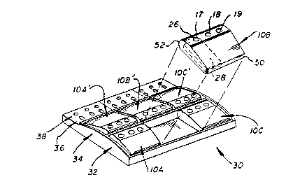
As shown in Figure 1, and in accord with one
aspect of the invention, the test wells comprise
wells 17, 18 and 19 in a row in housings lOA, lOB,
lOC, and lOA', lOB~, and lOC'. Each of the housings
in turn is mounted in a frame 30, so that a row 32 of
25 three housings lOA, lOB and lOC is formed adjacent
and generally parallel to a row 34 of three housings
lOA', lOB' and lOC'. Rows 32 and 34 are formed by
positioning the housings back to back. Each of these
rows then provides a row of wells, numbered
30 hereinafter as 32 and 34. Frame 30 can also
optionally include two rows of apertures 36 and 38,
each row for holding, respectively, a tube of
already-extracted patient sample (not shown) and a
swab tube holder (not shown). The side walls of
apertures 36 and 38 are sloped inward to hold the
tubes and tube holders, Fig. 1, or they can be
vertical. A divider 40, Fig. 2, is preferably
included to separate the two rows 32 and 34, Figure
. ?J
--8--
2. The swab holders, extraction tubes, frame 30,
reagent bottles (not shown) and all the housings
provide a Gonvenient test kit.
~ecause each.housing lOA, etc. has only 3
wells, the number of wells provided in either row can
be any multiple of 3 - e.g., 9 as shown, or 6 or 3.
In fact, by making frame 30 of any appropriate
length, it can be any multiple of 3.
Any desired construction can be given to
housings lOA, lOA', etc. Preferably it is that
described in U.S. Patent No. 4,847,199 and the
above-noted commonly owned application, the details
of which are expressly incorporated herein. The
filter membrane 24 in such housings is located at the
bottom of sloping walls 26, and underneath each such
membrane 24 is positioned a liquid-absorbing material
28 (shown in phantom, Fig. 1). A sliding vent bar 50
can be mounted on the front, and back portion 52 is
preferably rounded. (For simplicity, only housing lOB
illustrates the vent bar 50 and the sloping walls 26
in wells 17-19.)
In accordance with another aspect of the
invention, rows 32 and 34 of the housings are used as
follows (Figure 3): In the wells of row 34,
preferably only the materials for negative control
are deposited during the protocol. In the wells of
row 32, only the potentially color-producing
materials are placed, i.e., either the patient sample
(in most cases) or the positive control (in one well
only). Because the positive control may be run only
once in a day, any given set of nine wells in row 32
will probably only have patient (test) sample
liquid. Importantly, this arrangement means that no
well will be positioned between a well of row 32 and
its adjacent negative control well of adjacent row
34. Thus, there will be nothing to prevent an
accurate comparison of the color (if any) produced by
a patient sample in a well of row 32, with the
--9~
minimal or no color produced in negative control
wells of row 34. Most importantly, no positive
control well nor a patient sample well appears
between a well of row.32 and a well of row 34. If a
5 positive control well is run at all, it will be one
- of the wells in row 32.
The following then is a preferred protocol
for using the wells of rows 32 and 34, having already
extracted whatever chlamydia antigen may be present
in the patient samples: a) In a pair of wells, e.g.,
17, 17' of all the housings, 5 drops of the patient
sample (or the positive control, if that is to be
used at this time) i3 placed in each well. The
appropriate patient identification, or symbol +,
respectively (if the positive control is being
tested), is placed on label portions 70 and 70'. b)
Thus each of the paired wells is treated with a
different solution of different patient sample. c)
The sample solutions are allowed to drain through the
20 filter membrane. d) Thereafter, a wash solution is
added rapidly and turbulently to fill about 2/3 of
each well, and it is allowed to drain.
Next, e) two drops of the reagent comprising
the negative control solution noted above are added
to all the wells of row 34 only, and f) two drops of
the reagent comprising the labeled MAb specific to
chlamydia are added to all the wells of row 32 only.
g) All rows are allowed to incubate for two minutes,
then h) a turbulent wash is added to all the wells of
30 both rows.
Next, i) two drops of the reagent comprising
the dye ~olution noted above are added to all the
wells of both rows 32 and 34, and j) the wells are
allowed to incubate for 3 minutes. The wells are now
ready to be read, by visually comparing the presence
or absence of color produced in row 32 against the
2 ~
--10--
minimal (if any~ color of the negative control wells
of row 34. Presence of substantially more color in a
well of row 32 than is present in a well of row 34
means chlamydia iæ pr~sent in the sample tested. (As
u~ed herein, ~substantial~ means an amount that is
clearly distinguishable from that produced by the
negative control well.)
As a result, the color produced by the
patient sample wells of row 32, shown as hatch lines,
~igure 4, is easily contrasted with the lack of color
in the negative control wells of row 34. If a well
such as well 19 of housing lOC is as colorless as the
adjacent well 19' of housing lOC', the test is
negative for the sample in well 19.
It will be readily appreciated that the
above-described test apparatus and protocol is
equally useful to test for an antibody, for example,
the HIV antibody. In such a case, the membrane need
only be treated to cause the targeted antibody to
attach, as the first sequence of steps a)-d)
described above. The label that is then added can
be, e.g., a labeled antibody to that antibody, as is
well known.
It is not essential that the housings of
rows 32 and 34 be disposed back to back, as shown.
Alternatively, Figure 5, they can be placed in frame
30 so that they are back to front. Parts similar to
those previously described bear the same reference
numeral to which the distinguishing digit "0" is
added. Thus, frame 300 has in it a row 320 of
housings lOOA, lOOB and lOOC, and a row 340 of
housings lOOA~, lOOB~ and lOOC~. Each housing is
constructed and processed identically as described
for the previous embodiment. The only difference is
that housing lOOA~ has its front portion 500 adjacent
to back portion 520 of housing lOOA, and 30 forth for
the remaining pairs of housings.
Since there still is no intermediate well
disposed between the wells of row 320 and the wells
or row 340, such an arrangement also produces an
accurate and easy determination of positive or
negative patient samples.
As yet another alternative, it is not
essential that the negative control wells all occupy
only, e.g., row 34. Instead, Figure 6 one pair of
housings can be switched. Parts similar to those
previously described bear the same reference numerals
to which the distinguishing digits "00" have been
added. Thus, some of the wells of row 3200, those
provided by housing lOOOC', are negative controls
producing no substantial color to be compared with
substantia~ly colored wells of housing lOOOC in row
3400. (The remainder of row 3400, as provided by
housings lOOOA' and lOOOB', would still be negative
controls.) This works, because the patient sample
test wells of housing lOOOC, now in row 3400, are
still adjacent a substantially non-colored well with
no intervening color-producing well to confuse the
readings. The color-producing wells have been
hatched in Figure 6 to render clear the alternate
arrangement achieved by switching the positions of
housings lOOOC and lOOOC'. ~owever, such switching
as shown in Figure 6 is nQ~ as preferred as the
alignment shown in, e.g., Fig. 4, because the
operator could become confused as to which wells
should contain the negative control, etc.
As a further alternative, not shown, all the
wells of a given row, e.g., row 32 or 34, can be
provided in a single housing instead of a plurality
of housings. Still further, all of the housings for
both rows can be integrated into a single device.
The-invention has been described in detail
with particular reference to preferred embodiments
thereof, but it will be understood that variations
and modifications can be effected -~ithin the spirit
and scope of the invention.