Language selection

Search

Patent 2041356 Summary

Third-party information liability

Some of the information on this Web page has been provided by external sources. The Government of Canada is not responsible for the accuracy, reliability or currency of the information supplied by external sources. Users wishing to rely upon this information should consult directly with the source of the information. Content provided by external sources is not subject to official languages, privacy and accessibility requirements.

Claims and Abstract availability

Any discrepancies in the text and image of the Claims and Abstract are due to differing posting times. Text of the Claims and Abstract are posted:

  • At the time the application is open to public inspection;
  • At the time of issue of the patent (grant).
(12) Patent: (11) CA 2041356
(54) English Title: LASER DRILLING
(54) French Title: PERCAGE AU LASER
Status: Expired and beyond the Period of Reversal
Bibliographic Data
(51) International Patent Classification (IPC):
  • C08L 27/18 (2006.01)
  • B23K 26/18 (2006.01)
  • C08L 33/12 (2006.01)
(72) Inventors :
  • PHILBY, JONATHON D. (United Kingdom)
  • DAVIES, GLYNDWYR J. (United Kingdom)
(73) Owners :
  • AETC LIMITED
(71) Applicants :
  • AETC LIMITED (United Kingdom)
(74) Agent: GOWLING WLG (CANADA) LLP
(74) Associate agent:
(45) Issued: 1997-11-25
(22) Filed Date: 1991-04-26
(41) Open to Public Inspection: 1991-10-27
Examination requested: 1994-05-26
Availability of licence: N/A
Dedicated to the Public: N/A
(25) Language of filing: English

Patent Cooperation Treaty (PCT): No

(30) Application Priority Data:
Application No. Country/Territory Date
9009343.6 (United Kingdom) 1990-04-26

Abstracts

English Abstract


A material is described for preventing the
occurrence of damage to the backwall of a cavity within
a component during laser drilling of holes into said
component. The material comprises an acrylic resin
having polytetrafluoroethylene dispersed within it and
is polymerized before laser drilling. A method for
preventing such backwall damage occurring during laser
drilling using this material is also described and the
method comprises the steps of at least partially
filling the cavity in the component with a material
comprising an acrylic resin monomer and
polytetrafluoroethylene (PTFE), the monomer
incorporating a suitable initiator to promote
polymerisation, and allowing said material to
polymerise in situ in the cavity prior to laser
drilling.


French Abstract

L'invention est un matériau servant à empêcher l'endommagement de la paroi arrière d'une cavité à l'intérieur d'un composant durant le perçage de trous dans ce composant au moyen d'un laser. Ce matériau contient une résine acrylique dans laquelle un polytétrafluoroéthylène est en dispersion, et qui est polymérisée avant le perçage au laser. Une méthode utilisant ce matériau pour empêcher l'endommagement de la paroi arrière durant les opérations de perçage au laser est également divulguée. Dans cette méthode, la cavité qui est à l'intérieur du composant est au moins partiellement remplie avec un matériau contenant un monomère de résine acrylique et un polytétrafluoroéthylène, ce monomère contenant un agent d'amorçage approprié pour faciliter la polymérisation; le perçage au laser se fait pour permettre la polymérisation de ce matériau in situ dans la cavité.

Claims

Note: Claims are shown in the official language in which they were submitted.

THE EMBODIMENTS OF THE INVENTION IN WHICH AN EXCLUSIVE
PROPERTY OR PRIVILEGE IS CLAIMED ARE DEFINED AS FOLLOWS:
1. A method for preventing damage to an internal backwall of a
cavity defined within a component, during laser drilling of holes into said
component, the method comprising the steps of:
(a) at least partially filling the cavity in the component with a
material comprising a mixture of polytetrafluoroethylene dispersed in an acrylicresin monomer together with an initiator to promote polymerization of the
monomer, and
(b) allowing said material to polymerize in situ in the cavity prior to
laser drilling.
2. The method according to claim 1 wherein the acrylic resin
monomer is methylmethacrylate.
3. The method according to claim 2 wherein the
polyltetrafluoroethylene is present in the range 0.5% by weight to 30% by
weight.
4. The method according to claim 3 wherein the
polytetrafluoroethylene is present in the range 1% by weight to 10% by weight.
5. The method according to claim 3 wherein the
polytetrafluoroethylene is present in the range 2% by weight to 6% by weight.

Description

Note: Descriptions are shown in the official language in which they were submitted.


Laser Drilling
This invention relates to the drilling of holes, using
laser radiation into components having an internal cavity.
Laser radiation is often used for the precision drilling
of small holes in components used, for example, in the
aerospace industry.
Two methods for producing such holes with laser radiation
are available; direct drilling and trepanning. Direct
drilling involves the use of a "pulsed" laser wherein
material is removed little by little by individual pulses
of laser radiation concentrated on a small area. The
general technique involves directing a number of pulses of
laser radiation to burn through the material plus one or
more subsequent pulses to "clean out" the interior of the

- 2 - ~ 3 5 ~ - -
.
hole and to remove the rough edges left on the hole as the
laser emerges through the material.
Trepanning involves direct drilling of a small hole
through the material which is then enlarged by moving the
laser source and the component relative to one another
such that the edges of the hole are gradually removed.
During this enlargement process a significant proportion
of the energy derived from the laser passes straight
through the hole made and is not incident upon the
material it is desired to remove.
hen drilling holes, by either of the above methods, into
components having an internal cavity, a major problem is
,he prevention of damage to the internal back wall of the
cavily upon break .hrough by the laser beam. Such damage
is especially prevaient when drilling by the trepanning
method during which, only around 50% of the laser energy
is incident on the material being removed, the majority of
the rest of the energy passing down the already drilled
hole which acts as a "light pipe", maintaining a constant
beam width and so tending to maximise the backwall damage.
It is known to use paraffin wax containing up to 60% by
weight PTFE as a "laser-stopper" material to fill the
cavity of such components prior to laser drilling. Such
PTFE-filled wax disperses the laser energy incident upon

5 6 '
it and thereby prevents or reduces damage to the cavity
backwall. However, problems associated with the use of
P~FE-filled wax are that the wax tends to melt as the
component heats up and may drip out of the holes already
drilled; since laser drilling is often carried out in an
oxygen-rich atmosphere the wax is prone to burning as it
drips out of the component. Furthermore such waxes also
tend to leave a carbon-rich deposit or "char" on the
component which may chemically combine with the remelted
metal at the hole edges and can lead to cracking and
general weakening of the component.
It is an object of the present invention to provide an
improved cavity filling material, for use in the laser
drilling of holes in components having internal cavities,
to minimise damage occurring to the backwall of the cavity
~hen the ]aser beam breaks through the component surface.
It is a further object to minimise the other undesirable
chemical side effects which occur with known filling
materials.
According to a first aspect of the present invention there
is provided a material for use in the laser drilling of
components each defining at least one internal cavity
therein, the material acting to minimise damage occurring
to a backwall of the cavity due to the laser beàm, said

1 3 5 6
material comprising an acrylic resin monomer and
polytetrafluoroethylene (PTFE), the monomer incorporating
a suitable initiator to promote polymerisation of the
liquid monomer to form a solid polymer.
In one embodiment of the material the acrylic resin
monomer mav preferably comprise methylmethacrylate (MMA).
The resulting polymethylmethacrylate (PMMA) has many
advantageous features for the purposes of the present
invention; It leaves little or no char on degradation, it
has a relatively high melting point and a low oxygen index
and therefore does not tend to melt and drip out of the
component during drilling or to burn in an oxygen-rich
aLmosphere. Furthermore PMMA has good powers of dispersion
to laser ligh, and also acts as a type of "fibre optic",
that is to say PMMA lights up when the laser light hits
it; this feature is useful in detecting breakthrough of
the laser into the cavitv.
The propor.ion of PTFE dispersed in the resin may range
from very low levels of less than 0.5% by weight to very
high levels of over 70% by weight but is effectively
determined by the accessibility of the internal cavity in
the particular component to be drilled and the ease with
~hich the filler may be introduced. Increasing the
proportion of PTFE in the mixture also increases its

- 5 ~ 5 fi
viscosity hence high PTFE contents may not be suitable for
use when drilling components having very small and/or
complex cavities to which access is limited.
For the purposes of the present invention the PTFE is
preferably present in the range 0.5% by weight to 30% by
weight, more preferably 1% by weight to 10% by weight and
still more preferably 2% by weight to 6% by weight.
The initiator used to promote polymerisation of the liquid
monomer may be any free radical initiator known in the art
for such purposes. Examples of such initiators include
azobisisobutyronitrile and peroxides.
According to a second aspect of the present invention a
method for preventing damage to an internal backwall of a
cavity defined within a component during laser drilling of
holes into said component comprises the steps of at least
partially filling the cavity in the component with a
material comprising an acrylic resin monomer and
polytetrafluoroethylene (PTFE), the monomer incorporating
a suitable initiator to promote polymerisation, and
allowing said material to polymerise in situ in the cavity
prior to laser drilling
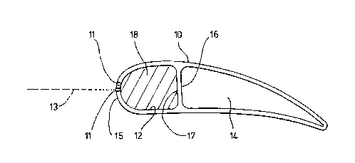
The invention will now be described more particularly by
means of the following Example and drawing which shows a

~ ~ 4 ~ 3 5 6
section through a turbine blade being laser drilled in
accordance with the invention.
In the drawing the turbine blade 10 has two simple
internal cavities, a front cavity 12 and a rear cavity 14
separated by an internal wall 1 the front face 17, of
which forms the backwall of the front cavity 12. Holes 11
are produced in the front surface, 15 of the blade by
means of pulses of radiation 13, incident upon the blade
front produced by a laser (not shown). The front cavity 12
is completely filled with a material 18, which acts to
disperse the laser energy after it breaks through the
front surface and thereby prevent or minimise any damage
to the backwall 17.
EXAMPLE
A turbine blade to be laser drilled contained a complex
cavity, from the root almost to the top, 70mm long
tapering down to a small cross-sectional area of
approximately 2mm . Numerous pillars spanned the cavity
thereby making the use of a solid PTFE laser barrier
impossible.
The barrier material comprised l9g of methyl methacrylate,
l.Og of Fluon L1~9 (trade mark) PTFE powder and O.5g of
azobisisobutyronitrile. These components were stirred

~'- ' 2~1 35fi
together for 30 seconds and drawn into a syringe to which
a lmm diameter flexible tube was then attached to direct
the liquid to the bottom of the blade cavity. The blade
was filled, in the upright position, to overflowing.
After one hour the barrier material had set and the blade
could be handled; after 24 hours at ambient temperatures
the blade was ready for drilling.
Drilling was carried out using a Nd-YAG (1064nm) pulsed
laser using oxygen gas fed through an axial jet to the
turbine blade surface to assist molten metal and vapour
removal.
The following laser parameters were used:-
Nozzle to workpiece gap = 10 mm
~2 pressure = 100 psi
Lens setting = 50 mm
Energy per pulse = 12 Joules
Pulse width = 0.6 msec
Lamp power = 3 Kw (x2)
After drilling was completed the barrier material wasremoved from the blade by burning out in a furnace at
700~C for 3 hours.

7 ~ ~ ~ 3 ~ ~ ~
Examination of the blade showed that good hole shape and
quality had been obtained with no damage to the backwall
of the blade cavity and no chemical reaction between the
filling material and the metal adjacent to the hole walls.

Representative Drawing
A single figure which represents the drawing illustrating the invention.
Administrative Status

2024-08-01:As part of the Next Generation Patents (NGP) transition, the Canadian Patents Database (CPD) now contains a more detailed Event History, which replicates the Event Log of our new back-office solution.

Please note that "Inactive:" events refers to events no longer in use in our new back-office solution.

For a clearer understanding of the status of the application/patent presented on this page, the site Disclaimer , as well as the definitions for Patent , Event History , Maintenance Fee  and Payment History  should be consulted.

Event History

Description Date
Time Limit for Reversal Expired 2001-04-26
Letter Sent 2000-04-26
Grant by Issuance 1997-11-25
Inactive: Application prosecuted on TS as of Log entry date 1997-09-22
Inactive: Status info is complete as of Log entry date 1997-09-22
Pre-grant 1997-06-03
Inactive: Adhoc Request Documented 1997-04-28
Deemed Abandoned - Failure to Respond to Maintenance Fee Notice 1997-04-28
Notice of Allowance is Issued 1996-12-10
Request for Examination Requirements Determined Compliant 1994-05-26
All Requirements for Examination Determined Compliant 1994-05-26
Application Published (Open to Public Inspection) 1991-10-27

Abandonment History

Abandonment Date Reason Reinstatement Date
1997-04-28

Fee History

Fee Type Anniversary Year Due Date Paid Date
Registration of a document 1997-05-21
Final fee - standard 1997-06-03
MF (patent, 7th anniv.) - standard 1998-04-27 1998-03-16
MF (patent, 8th anniv.) - standard 1999-04-26 1999-03-17
Owners on Record

Note: Records showing the ownership history in alphabetical order.

Current Owners on Record
AETC LIMITED
Past Owners on Record
GLYNDWYR J. DAVIES
JONATHON D. PHILBY
Past Owners that do not appear in the "Owners on Record" listing will appear in other documentation within the application.
Documents

To view selected files, please enter reCAPTCHA code :


To view images, click a link in the Document Description column. To download the documents, select one or more checkboxes in the first column and then click the "Download Selected in PDF format (Zip Archive)" or the "Download Selected as Single PDF" button.

List of published and non-published patent-specific documents on the CPD .

If you have any difficulty accessing content, you can call the Client Service Centre at 1-866-997-1936 or send them an e-mail at CIPO Client Service Centre.


Document
Description 
Date
(yyyy-mm-dd) 
Number of pages   Size of Image (KB) 
Cover Page 1997-11-10 1 48
Abstract 1996-12-10 1 21
Abstract 1993-12-20 1 10
Cover Page 1993-12-20 1 19
Claims 1993-12-20 2 54
Drawings 1993-12-20 1 11
Description 1993-12-20 8 279
Description 1996-12-10 8 188
Claims 1996-12-10 1 28
Drawings 1996-12-10 1 9
Representative drawing 1997-11-10 1 5
Maintenance Fee Notice 2000-05-24 1 178
Fees 1997-04-11 1 38
Fees 1996-04-12 1 32
Fees 1995-04-12 1 40
Fees 1993-04-08 1 31
Fees 1994-04-12 1 41
PCT Correspondence 1991-12-18 1 30
PCT Correspondence 1997-06-03 1 37
Courtesy - Office Letter 1991-10-25 1 62
Courtesy - Office Letter 1994-06-30 1 32
Examiner Requisition 1995-08-11 2 68
Prosecution correspondence 1994-05-26 1 42
Prosecution correspondence 1995-11-08 1 31
Prosecution correspondence 1994-09-02 12 377
Prosecution correspondence 1994-05-26 1 28