Note: Descriptions are shown in the official language in which they were submitted.
20~15~9
Docket RIB 020 P2 -1-
IMPACT SADDLE FOR CONVEYOR BELTS
Backqround of the Invention
The invention relates to belt-type conveyor
system~, and more particularly to the conveyor system~ which
S carry bulk materials, such as for carrying crushed stone,
gravel, coal and the like. Commonly, the upper runs of the
conveyor belts are supported on conveyor belt idlers, which
form a particularly troughing angle with the upper run of
the belt. Such conveyor systems have a loading or impact
zone, where the material to be carried by the belt i8 loaded
onto the belt surface. The force of the loading of the
material, at the loading zone, applie~ a particularly high
stress to the belt and to the belt-supporting idlers.
Commonly, special idler rollers are used in the
loading zone, known a~ impact rollers, which are specially
con~tructed to absorb the loading impact forces. An impact
idler assembly is a heavy-duty version of the normal
conveyor belt idler, in which the rollers are more resistant
to impact loading. The rollers, them~elve~, are usually ~`-
three in number, that i~, two side rollers and a bottom
roller, mounted for rotation on a common support frame, and
the rollers may be formed with a cu3hioning curface, such as ;
in the form of a stack of discs, to resist impact. A good
~; example of an impact idler consists of the stacked rubber
disc impact idler, types HG and HS, of Continental Conveyor
& Equipment Company, Inc., Windfield, Alabama 35594. Thus
the conventional idler roller as~embly con~ists of a series
of transversely oriented individual rollers ~ounted or -~
supported in end-to-end relation on a common tran~verse
support or saddle frame, and mounted 80 that the running
surfaces of the rollers define the desired troughing angle.
'.
,
. . . - ,~
2 [)415~9
Docket RIB 020 P2 -2-
Impact rollers are, themselves, subject to
premature and often unpredictable failures. For example,
the idler bearings may fail due to the high loading or due
to spill-overs or contamination from the material being
carried, or from dust. Also, the impact roller surface may
become damaged or out of round. When a bearing or impact
idler fails, the impact roller can jam, causing damage to
the belt or requiring shut down of the conveyor sy~tem.
A number of solutions have been proposed, mo~t of
which require the recon~truction of the impact zone by the
substitution of a slider bed in the zone. A typical slider
bed, algo known as a belt cradle assembly, is shown in
Andersson, U. S. Patent No. 4,793,470 issued December 27,
1988. The series of impact rollers i~ replaced by a single
cradle at the impact area, the cradle is formed with a
series of longitudinally extending, transver~ely spaced
slats or bars formed of high molecular weight polymer
material, cu~hioned by a rubber underlayer. Such slider
beds are particularly effective in providing a long wearing
belt ~upport, at the impact zone, and in eliminating the
problems of failures of impact idlers.
The principal disadvantage of the impact zone
- slider beds, of the general kind shown in Andersson, resides
in the relatively high initial cost of the conversion to
such a slider bed, usually requiring a shut down and -
redesign of the conveyor system, to accept a ~lider bed at
the impact zone. Also, in the event it should become
neces~ary to repair or replace one of the longitudinal bar~,
this usually requires a shut down of the conveyor since the
bars are usually only accessible from a position beneath the
upper run of the belt.
::
:
Z04~S9 9
Docket RIB 020 P2 -3-
A need exists for an improved impact idler, which
can be sub~tituted directly for an existing idler, and
provide the advantages which are afforded by costly
conversion to a bar-type impact bed or slide as~embly.
summarY of the Invention
This invention is directed to an impact gaddle for
a belt-type bulk material conveying system i8 a direct
~ubstitute for an impact idler assembly, and more
particularly to an impact saddle which has no moving parts.
The impact saddle of this invention i~ designed as a direct
replacement for interchange with a ~tandard impact idler
assembly presently in use, requiring no substantial
modification of the conveyor structure, other than the
removal of the existing impact idler assembly, including the
idler roller support frame, and the substitution of the
~upport frame and impact saddle of this invention.
The invention provides a support frame which
defines a pair of generally T-shaped parallel supports,
extending in transverse relation to the direction of belt --
movement. The T-shaped ~upports form an upwardly facing -~
concavity or curve which approximates the troughing angle of
the idler~. These supports receive thereon a low friction
belt support in the preferable form of a series of
replaceable low-friction polymeric segments, positioned one
next to the other transversely of the width of the
supporting frame. The upper surfaces of the ~upport, a~
; defined by the ~egments, which may be planar or flat,
provide a support for the belt. Preferably the segments are
formed as blocks of ultra-high molecular weight
polyethylene, with elastomeric or rubber impact cu~hions
2~sg:9
Docket RI8 020 P2 -4-
therein, or alternatively, may be formed of a self-
lubricating urethane.
The individual ~egments, mounted on the ~upporting
frame, are replaceable after in~tallation without having to
remove the frame. They are assembled by threading or
sliding on the frame and replaced simply by driving new
segments on from one side and allowing the old ~egments to
come off the opposite side.
Impact saddles, in accordance with this inventionr
replace exi~ting impact idler assemblies and can be spaced
apart along the impact zone as i8 common with impact idlers,
or can be spaced in immediate side-by-side relation to
provide a continuous support region for the belt, such as
for use in ~evere or heavy impact situations. The segments -
themselves are formed with a double T-shaped slot design for
mounting on T-shaped ~upport members of the saddle frame.
This design holds the individual segments in place without
the need for clips or bolts. The segments, which may be
formed of ultra-high molecular weight polyethylene, have
upper surfaces which, collectively, define a transversely
extending belt supporting impact surface.
While the T-shaped ~upport members of the saddle
frame may be smoothly curved to approximate the desired
troughing angle, the segments may be formed with ~traight
lines and with flat upper belt-~upporting surfaces. The
transversely abutting ends may be cut at a slight angle 80
as to permit the individual segments to come flat against ~
each other, with the upper ~urfaces approximating a curve. ~-
l~ Preferably, a pad of impact absorbing rubber ;~
¦~ 30 material i~ positioned between the segments and the support,
for distributing the impact load from any one ~egment to the ~;
: ~:
,:~ .
: ~:
.........
2~ 5~ ~ -
Docket RIB 020 P2 -5-
supporting frame, thereby preventing cracking or damage to
the individual segments. The impact rubber may be in the
form of a continuous tran~versely oriented pad or ~trip, one
for each of the T-shaped slots, and positioned between the
slot and the corre~ponding ~upport member of the saddle
frame. A tough, resilient low-friction bed i~ thus
provided, shaped to the natural contour of the loaded belt
in accordance with the desired troughing angle. The
individual segments, supported on the frame, may be replaced
as required without the necessity for removing the support
frame.
The invention may be characterized as an improved
impact saddle for a bulk material conveyor belt having a
non-moving impact sliding surface which takes the place of a
conventional impact roller assembly, in an impact zone, ~ ;
comprising or characterized by a support frame adapted to be
positioned in transverse relation to the length or the -
direction of movement of the conveyor belt and having a
~; width, in the direction of belt movement, which is
approximately the same as that occupied by a conventional
impact roller-type idler, the frame defining an upper curved
impact ~egment support member. A plurality of polymeric
low-friction segments are mounted or threaded on the member,
the segments collectively defining upper transver~ely
extending belt-supporting surfaces. The segments may be
formed of high density material, may be identical to each
other, and in a further aspect of the invention, the support
member may comprise a pair of side-by-side T-shaped supports
in which the segments are formed with corresponding T-~haped
slot~ which are adapted to receive the supports for the
threading of the segments onto the ~upports.
~ "~
20415~ 9
Docket RIB 020 P2 -6-
8rief Description of Accompanyinq Drawinq~
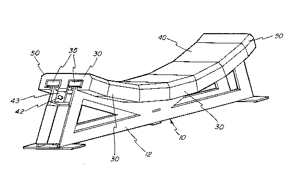
Fig. 1 is a perspective view of an impact saddle
assembly in made accordance with this invention:
Fig. 2 is a ~ide elevation, looking in the
direction of belt movement, of the saddle assembly of Fig.
l;
Fig. 3 i8 a top view of the saddle assembly; and
Fig. 4 is an enlarged cross-sectional view through the
assembly, and through one of the impact segments.
DescriPtion of Preferred Embodiment
Referring to the figures of the drawing, which
illustrate a preferred embodiment of the invention, an
improved impact ~addle for use with a bulk material conveyor
is illustrated generally at 10 in Fig. 1. The saddle 10 has
a non-moving sliding impact surface and i8 used in pLace of
a conventional impact roller assembly, in an impact zone.
The saddle 10 includes a support frame 12 formed
in two identical halve~, namely a right-hand support frame
12a and a left-hand support frame 12b, as best shown in the
sectional view of Fig. 4. The frame sections 12a and 12b
are mounted with end flanges 14 in abutting and welded
relation, and are formed with outwardly extending feet 15 by
which a frame may be secured or attached to a suitable
support.
The frames 12a and 12b have vertically extending
support portions 16 which terminate in a pair of parallel,
~; , side-by-side T-shaped support members 20.
- ~ ~The support frame 12 is adapted to be positioned
in transverse relation to the length or direction of
movement of a bulk-type conveyor belt ~not shown) and is
~-formed with an oYerall width in the direction of belt
.::
::
J
~ 2~4~$~ 9
Docket RIB 020 P2 -7-
movement which is approximately the same as that occupied by
a conventional impact roller-type idler. The T-~haped
support members 20 are curved tran~versely of the width of
the frame in an approximate duplication of the desired
troughing angle of the belt.
The members 20 ~upport low friction be't-engaging
means in the form of a plurality of individual, identical
impact segments 30. For this purpo~e, the ~egments 30, as
shown in the sectional view of Fig. 4, are provided with a
pair of T-shaped slots 32 in their lower surface which are
proportioned to receive one of the T-shaped support members
20 therein. The individual segments 30 are isolated from
the T-shaped support members 20 by tran~versely extending
blocks or pads 35 of rubber materiaL. In a typical
installation, the~e pads 35 may be about 1.0 inch thick, and
as wide a~ the members 20, and may extend continuousLy along
the uppex length of the upper surface of the support members
20 and suitably bonded thereto. They may be made of a
rubber material having a durometer of approximately 40.
- 20 The individual segments 30 are preferably formed
of ultra-high weight molecular material, such as UHMW
polyethylene, although other material materials may be used,
such a~ a self-lubricating urethane. The cushions defined
,~ by the pads 35 permit the individual segments 30 to move on
the support frame 12 independently of an adjacent ~uch
segment.
As previously noted, the segments 30 may be
configured in an identical manner and are stacked or
threaded end-to-end on the support 12, such as illustrated
in Figs. 1, 2 and 3. The segments 30 have generally planar
or flat upper belt-supporting surfaces 40, although it is
,:,
, .
2~549
Docket RIB 020 P2 -8-
within the scope of this invention to employ curved
surfaces.
A plurality of the individual segment~ 30 are
mounted in abutting end-to-end relation transver~ely of the
support frames 12, as illustrated in Figs. 1 and 3, and are
retained in position by a bolt 42 and clip 43 at the
opposite ends. The abutting end surfaces 45, Fig. 2, may be
formed with a slight taper 80 as to facilitate the flat end-
to-end abutment of the individual segments, as shown. The
top surfaces 40 may be provided with end chamfers or tapers
50, along the transverse opposite edges, to provide on-
running and off-running surfaces for the overlying belt.
Preferably, the flat upper surfaces 40 of the
segments 30 present a transversely continuous or relatively
unbroken support surface for the belt, as illustrated in
Fig. 1 in that there is no appreciable gap or space between
the individual impact segments 30. However, if desired,
grooves extending in the direction of belt movement may be
formed between individual segments 30 or formed in the
individual planar ~urfaces 40 in appropriate circumstance~
The entire saddle assembly 10 i8 designed to be
positioned beneath the upper run of the belt of a bulk-type ~-~
conveyor, in the exact space occupied by an existing impact
roller saddle assembly. A plurality of individual impact
saddles 10, in accordance with this invention, may be placed ;
in side-by-side relation and distributed along an impact
zone, as required, for proper support of the belt. The
impact saddles may thus be ~paced from each other or, where
~ desired, they may be placed in immediate adjacent relation
- 30 to form, in effect, a relatively continuous impact support
surface. ;~
:' 'Z~15~ ,
Docket RIs 020 P2 -9-
Once the support ~addle according to thi~
invention i8 installed, the individual segments 30 are
replaceable without moving the idler frame 12 or without the
necessity of moving the belt. The retainer, in the form of
S the bolt~ 42 and clips 43, may be removed, and the segments
may be driven off simply by driving new ~egments from one
side of the frame 12 onto the T-shaped supports 20, and the
old or worn segments 30 will come off of the opposite ~ide
of the saddle 10.
The double T-slot design i8 particularly
advantageou~ as it holds the individual segments 30 in
place, on the saddle, without the need of additional
external bolts or clip8. In other words, the segments 30
are, in effect, ~elf-holding since they are threaded onto
the saddle frame 12. Also, while the invention has been
described as employing a plurality of individual segments
38, it is within the scope of the invention to employ a h
single or one piece formed or shaped impact member in place
of the segments.
It will be understood that the individual support
frames will be tailored in accordance with the conveyor
belt, and the troughing angle, 8uch as typically a 25-, 35
or 45- troughing angle. Further, while the segments 30 may
be identical, the angles of the abutting surfaces 45 may be
~ 25 adjusted or varied, as required, 80 that the segments may
-~ come into flat abutment with each other, with the upper
surface 40 approximating a curve. For example, for segment ~-~
30 designed for a 45- troughing angle, the end ~urfaces 45
may be formed at a 4-1/2- angle to the ~urface 40 ~o that
the ~egment is somewhat narrower at its top than at its
bottom. Thus the individual segments may be 12 inches wide,
,. . ..
~4~5~ 9
Docket RIB 020 P2 -10-
4 inches deep, with a length transverse to the belt which
may vary in accordance with belt width, ~o that a whole
number of segments may be employed, ~uch as nine segments
typically illustrated in Figs. 2 and 3.
While the form of apparatus herein described
constitutes a preferred embodiment of this invention, it i8
to be understood that the invention is not limited to this
precise form of apparatus, and that changes may be made
therein without departing from the scope of the invention
which is defined in the appended claims.
What i8 claimed is:
;,'''
.'
~: .
: ~
~ :.
~,
~;..
,
. . . - ' ' '.~