Note: Descriptions are shown in the official language in which they were submitted.
8803(~
b ~
VARIABLB FORCE 80LENOID
HYDRAULIC CONTROL VALVB
BACKGROUND OF THE INVENTION
Field of the Invention
This invention relates to a solenoid designed to
achieve a substantially constant output force over a wide
range of solenoid armature displacement positions and a
substantially linear output force-current relationship.
More particularly, the present invention relates to a
variable force solenoid hydraulic control valve assembly
having an armature geometry which maximizes the primary
radial working gap area between the armature and solenoid
core and provides a secondary flat faced working gap. The
forces produced across the working gaps and the forces
generated by the hydraulic pressure balance the solenoid
return spring at various armature positions for a given
input current to produce a controlled pressure output,
while minimizing the size of the solenoid configuration.
Description of the Prior Art
Variable force solenoids are useful in a number
of applications where a constant output force at a given
input current is desired, independent of the displacement
or stroke of the solenoid armature. A common application
for such solenoids is within a vehicle transmission, where
the solenoid is combined with a flow control valve to
actuate and deactuate hydraulic clutch packs. ~y
88030
constructing the solenoid to produce a generally constant
output force, related to a given controlled hydraulic
pressure output, for a set input current throughout the
armature stroke, the armature position (as well as the
position of the control valve operatively connected to the
armature) can then be used to modulate the operation of
hydraulically actuated devices.
A resultant sum of forces can be balanced to
achieve the function of the solenoid. A first force is
defined solely by the force exerted against the armature
by a resilient return spring. The first or spring force
is determined by the spring rate of the return spring and
the armature displacement. A second force is defined by
the hydraulic pressure acting on a control valve face,
which is operatively connected to the armature. A third
force is defined by the electromagnetic force obtained by
the application~of current to the solenoid. By properly
calibrating the spring constant of the return spring, the
effective area of the control valve face and the range of
electromagnetic forces obtainable, a given input current
can be used to balance the first, second and third forces
so as to cause the control valve to operate as a variable
orifice. Such an orifice is useful in modulating the
output pressure.
~5 The strength of the third or electromagnetic
force necessary to operate such a hydraulic control system
is dependent on the number of conductive windings, the
applied current and the structure of the magnetic flux
circuit. The structure of the magnetic flux circuit is in
turn dependent on several factors, one of which is the
permeability of existing air gaps to the passage of
magnetic flux. In past solenoid configurations, effective
88030
2 u ~ s ~ ~
--3--
air gaps often dictated very close tolerances between the
armature and the pole piece, due to the unavailability of
increasing the overall size of the solenoid within the
confined spaces of a vehicle application. An example of
such a solenoid configuration may be seen in U.S. Patent
4,579,145, to Leiber et al. Allowing the tolerances to
become less critical as an alternative to the relatively
high cost and low reliability of very close gap tolerances
undesirably increases the overall size of the solenoid.
Accordingly, a solenoid capable of producing a useful
output force in a small, economically manufactured unit is
desired.
Accordingly, it is an object of this invention
to provide a solenoid which creates a useful output force.
It is also an object of this invention to
attempt to obtain a maximum possible solenoid output force
without appreciably increasing the solenoid size so as to
expand the usefulness of the solenoid.
It is a additional object of this invention to
increase the solenoid magnetic flux circuit permeability
by increasing the magnetic flux air gap area, where the
magnetic flux intensity is inversely proportional to the
gap separation and proportional to the area of the gap.
Further, it is an object of this invention to
provide a solenoid for use in a hydraulic control valve
that is operative according to a substantially linear
relationship between a solenoid input current and a
control valve output pressure independent of the initial
armature position.
88030
~ ~J '~ ~ `7~,3
Finally, it is an object of this invention to
provide a solenoid for use in a hydraulic control valve
that is operative accordin~ to a substantially linear
relationship between a solenoid input current and a
S control valve output pressure independent of the hydraulic
control valve input pressure.
These and other objects of the this invention
may be determined by a review and understanding of the
following disclosure.
SUMMARY OF THE INVENTION
The present invention comprises an electrically
actuated solenoid for use in a hydraulic control valve.
The invention provides the control valve with the ability
to generate a predetermined output pressure primarily as a
function of the solenoid input current. An input
pressure, provided to the control valve, is regulated so
as to provide a desired maximum controlled output pressure
regardless of the magnitude or variation of the input
pressure. Accordingly, where the input pressure exceeds
the desired maximum controlled output pressure, the
excessive input pressure is selectively bled to a low
pressure hydraulic return circuit by displacement of a
control valve operatively connected to the solenoid
armature.
When a lower controlled output pressure is
desired, the solenoid is provided with an input current so
as to create a magnetic flux circuit within the solenoid,
which $ncludes the solenoid armature. The magnetic flux
circuit thus causes displacement of the armature and
additional displacement of the control valve so as to
88030
2 `~
-5-
increase the pressure bled to the low pressure hydraulic
return circuit and to reduce the controlled output
pressure.
The solenoid is provided with an enhanced
armature and pole piece configuration that provides a
selectable output force dependent solely on a
substantially linear relationship with the solenoid input
current, regardless of the displacement of the armature
relative to the pole piece. The enhanced configuration,
by increasing the air gap surface area and increasing the
air gap permeability, favorably increases the output force
obtainable from a solenoid of relatively small physical
dimensions. The resulting improved output force versus
current characteristics make the use of the solenoid of
the present invention possible in a hydraulic control
system.
Thus, regardless of the initial displacement of
the control valve and armature combination as determined
by the input hydraulic pressure upon initiation of the
solenoid input current, a predictable and repeatable
controlled output pressure is obtainable in a small,
relatively inexpensive unit.
BRIEF DESCRIPTION OF THE DRAWINGS
FIG. 1 is a cross-sectional view along the
longitudinal axis of the variable force solenoid, showing
the improved solenoid armature and pole piece
configuration according to the present invention.
88030
~ ~3 7~
FIG. 2 is a cross-sectional view of a first
embodiment along the longitudinal axis of the variable
force solenoid of the present invention combined with a
hydraulic control valve for use in a hydraulic circuit
adapted to operate a hydraulically actuated device.
FIG. 3 is a cross-sectional view of a second
embodiment along the longitudinal axis of the variable
force solenoid of the present invention combined with a
hydraulic control valve for use in a hydraulic circuit
adapted to operate a hydraulically actuated device.
It should be understood that the drawings are
not necessarily to exact scale and that certain aspects of
the embodiments are illustrated by graphic symbols,
schematic representations and fragmentary views. It
should also be understood that when referring to physical
relationships of components by terms such as "upper~,
~lower~, ~upward~, ~downward~, ~vertical~, nhorizontaln,
~left~, ~right~ or the like, such terms have re~erence
solely to the orientation depicted in the drawings,
Actual embodiments or installations thereof may differ.
It should also be understood that the term ~passageway~ is
not necessarily limited to a tubular path but may
encompass communicating spaces, chambers and the like.
While much mechanical detail, including other
plan and section views of the particular embodiment
depicting have been omitted, such detail is not per se
part of the present invenkion and is considered well
within the comprehension of those skilled in the art
in the light of the present disclosure. The resulting
simplified presentation is believed to be more
readable and informative and readily understandable by
88030
!'^' ~'3
those skilled in the art. It should also be understood,
of course, that the invention is not limited to the
particular embodiment illustrated.
DETAILED DESCRIPTION OF THE PREFERRED EMBODIMENTS
Referring to the drawings, where like or similar
character references refer to like or similar features
throughout the views, Figure 1 shows one embodiment of a
solenoid 10 located within a housing 12 preferentially
constructed of a material permeable to a magnetic flux,
such as iron. Located along the central axis of the
housing 12 is a pole piece 14, which is also
preferentially magnetically permeable. Within an annular
cavity 16, ~ocated at a intermediate radial position
between the housing 12 and the pole piece 14, is an
electrical winding or conductive coil 18. The conductive
coil 18, preferably constructed of copper, is connected to
an electric current source (not shown) in the well known
manner. When excited by an electric current, the coil 18
induces a magnetic field to flow in a well known circular
path along a line of flux roughly defined by the housing
12, the pole piece 14 and at least a portion of an
ar~ature 20. The pole piece 14 extends beyond the coil
18, toward the armature 20, and is provided with a flange
22. A flange face 23 is formed on the flange 22 on the
surface closest to the armature 20. The flange 22 serves
to secure the coil 18 and also serves to form the
magnetically operative surfaces of the pole piece 14,
which will be discussed presently.
88030
Extending through the axis of the pole piece 14
is a cylindrical cavity 24, which allows access from the
exterior of the solenoid 10 to a set screw 26. The
cylindrical cavity 24 is preferably tapped so as to form a
threaded cylindrical channel. A set screw 26 is provided
with mating threads to the cavity 24 and is preferentially
equipped with means to apply torque, such that rotation of
the set screw 26 within the cavity 24 will cause
longitudinal displacement of the set screw 26 within the
cylindrical cavity 24. A solenoid spring seat 28,
positioned between a return spring 30 and the set screw
26, may thus be selectively positioned along the center
axis of the solenoid 10 to modify the slope of the
substantially linear solenoid output force-input current
relationship.
The solenoid spring seat 28, preferability
constructed of a non-magnetic material, is held in
position and urged against the set screw 26 by the
compressive force exerted by the return spring 30 in
operative contact with the armature 20. The spring seat
28 is provided with a retaining edge 32, such that the
return spring 30 is restrained from radial motion and
misalignment. The spring 30 is initially compressed upon
installation and remains compressed thereafter. The
initial return spring 30 compression, however, is subject
to adjustment by means of the set screw 26 as noted above.
Opposite the spring seat 28 and in operative contact with
the return spring 30 is an armature recess 34 formed in
the armature 20. The recess 34 defines a cylindrical
cavity 38 and a circular bearing surface 36, through which
the return spring 30 applies a force onto the armature 20
88030
2 . ~ ~
in proportion to the compression of the return spring 30.
The diameter of the cylindrical cavity 38 is sufficient to
contain the return spring 30 to prevent radial motion and
misalignment of the return spring 30 and to allow the
armature 20 to approach the retaining lip 32 of the spring
seat 28 without physical interference.
Armature 20 is provided with a circular face 40,
located opposite the flange face 23 of the flange 22 of
the pole piece 14 by a distance FF, which will be
discussed presently. An outer face 41 is located opposite
the face 40. The outer periphery of the circular face 40
defines an annular ring 42. The inner circumferential
surface of the annular ring 42 defines an armature radial
working gap surface 44. A cooperating radial pole piece
~orking gap surface 48 is operationally located on the
outer surface of flange 22, such that the overall working
gap is preferably approximately 0.015 inches. An armature
return gap surface 46, defined by the outer
circumferential surface of the ring 42, cooperates with a
reciprocal housing return gap surface 50 defined by the
inner circumferential surface of the housing 12 to form
the return gap RR. The return gap RR is also preferably
approximately O.OlS inches.
The armature 20 is maintained in an axial
position via a diaphragm spring 53, which is attached to
the armature 20 via a valve coupling pin 52 and a threaded
retainer 54. The valve coupling pin 52 threadingly
engages a tapped orifice 56 provided in the armature 20.
The orifice 56 extends through a flat surface 60 of the
armature 20 to the circular bearing surface 36. The flat
base 60 is thus positioned and retained against the
88030
--10--
diaphragm spring 53 via the threaded retainer 54 and the
valve coupling pin 52. The diaphragm spring 53 extends
outward radially so that its the outer periphery rests
engagingly against a rib 62 formed on the inner
circumferential surface 50 of the housing 12. Thus, axial
motion of the outer periphery of the diaphragm spring 53
is prevented.
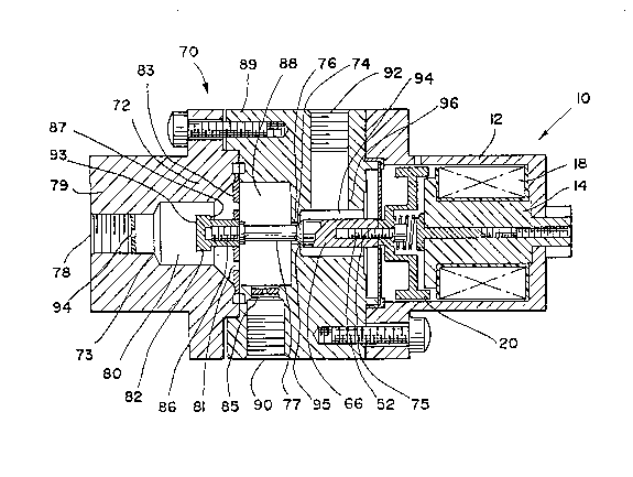
Applied to a flow control valve, the solenoid of
the present invention may be seen in Figure 2. The
control valve assembly 70 includes the solenoid 10 and a
valve assembly 72 located within the two housing members
79 and 89. The control valve assembly 70 includes one
fluid inlet and two fluid outlets. A fluid inlet port 78
is supplied with system hydraulic fluid no lower than 60
psig. Fluid thus enters the control valve assembly 70 and
flows through a restriction orifice 94 (preferably sized
to about 0.030 in.) and an inlet orifice 73 into a first
control chamber 80. A controlled fluid outlet port 90 is
also in communication with the first control chamber 80
via a second control chamber 88 and a controlled fluid
outlet orifice 85. A bypass pressure outlet 92 is in
communication with a bypass chamber 94 via bypass orifice
96. The control chambers 80 and 88 and the bypass chamber
94 are selectively in communication via the valve assembly
72.
The valve assembly 72 further includes a poppet
valve 74 positioned to selectively allow fluid flow
through a control orifice 76 located within a valve seat
95. The poppet valve 74 further includes a connecting
member 66, which is provided with a tapped cylindrical
cavity 75 threadingly connected to the valve coupling pin
88030
? -~ 5~
-lL-
52, as described above. Fixedly connected to the opposite
end of the poppet valve 74 and further comprising the
valve assembly 72 is a transfer pin 77 and a pressure
responsive face member 82. Face member 82 is provided
with a flat face 93 and a smaller opposite annular face
87. A tapped cylindrical cavity 86 is also provided which
threadingly engages the threaded end of the transfer pin
77.
The valve assembly 72 is maintained in an axial
position via a diaphragm spring 83, which is fixedly
attached to the valve assembly between the transfer pin 77
and face member 82. The diaphragm spring 83 extends
outward radially so that its the outer periphery is
received at the interface between the two members 79 and
89 of the control valve assembly 70. Thus, axial motion
of the outer periphery of the diaphragm spring 83 is
prevented. The diaphragm spring 83 is further provided
with apertures 81 positioned intermediate the center and
periphery of the diaphragm spring 83 so as to provide
constant fluid communication between the control first
control chamber 80 and the second control chamber 88.
As noted earlier, the resultant force obtained
from the several forces acting on the solenoid armature 20
is employed to selectively modulate the operation of the
control valve assembly 70. The control valve assembly 70
operates essentially as a bypass valve. The input
pressure of a hydraulic fluid of at least 60 psig is
supplied to the inlet port 78. Restriction orifice 94
acts to retard large flow rates, yet is su~ficient, at the
preferable inner diameter of about 0.030 in., to
communicate a faithful pressure signal at relatively low
88030
~ r~
--12 ~
flow rates into the first control chamber 80 and the
second control chamber 88. The pressure responsive face
member 82 is thus exposed to the inlet pressure. As the
flat face 93 of the face member 82 is greater than the
annular face 87 of the face member 82, pressure in the
first control chamber 80 will tend to produce the second
force urging the face member 82, the transfer pin 77, the
poppet valve 74, the connecting member 66, the valve
coupling pin 52 and the armature 20 against the return
spring 30.
The return spring 30, however, tends to produce
the first force seeking to restore the armature to its
initial position when compressed. When the inlet pressure
is about 60 psig or less, the second or pressure force is
less than the first or spring force. Thus, the face
member 82, the transfer pin 77, the poppet valve 74, the
connecting member 66, the valve coupling pin 52 and the
armature 20 remain stationary under the influence of the
first force. Under these circumstances, the valve
assembly 72 remains closed, as the second force is
insufficient to move the poppet valve 74 away from the
valve seat 95. The pressure signal into the first control
chamber 80 and the second control chamber 88 is thus
allowed to flow only through the controlled outlet orifice
85 and the controlled outlet port 9~ to the hydraulically
actuated device, such as a hydraulic clutch pack.
If the inlet pressure is greater than 60 psig,
the second or pressure force is calibrated to exceed the
first or spring force. Thus, the face member 82, the
transfer pin 77, the poppet valve 74, the connecting
member 66, the valve coupling pin 52 and the armature 20
88030
~ F~
-13-
will be displaced slightly to the right due to the second
force. The valve assembly 72 is thus caused to slightly
open as the second force is sufficient to move the poppet
valve 74 away from the valve seat 95. The pressure signal
S into the first control chamber 80 and the second control
chamber 88 is then allowed to flow through the bypass
chamber 94, the bypass orifice 96 and the bypass outlet
port 92 to a low pressure return circuit as well as the
controlled outlet orifice 85 and the controlled outlet
port 90 to the hydraulically actuated device. As the
relatively low flow resistance favors the bypass outlet
port 92, pressures above about 60 psig are thus caused to
bleed through the valve assembly 72 until the pressure in
the control chamber 80 is again returned to 60 psig.
Accordingly, a regulated maximum pressure can be
consistently provided to the hydraulically actuated device
regardless of the magnitude of an input pressure above 60
psig.
The third force, or the electromagnetic force,
arises from the magnetic flux flowing through the solenoid
10 and the armature 20 and can be used to cause the valve
assembly 72 to operate as a variable orifice to control
the controlled outlet pressure selectively between the
maximum regulated pressure and a minimum or very low
pressure. When the controlled output pressure delivered
by the controlled output port 90 is to be decreased (e.g.,
to decrease the pressure delivered to the hydraulically
actuated device), an input current is applied to the coil
18. The input current, proportional to the desired
decrease in the controlled output pressure, thus induces a
88030
?1 I~J'~i ~3
-14-
magnetic flux density of a fixed magnitude along the flux
path created by the pole piece 14, the housing 12, the
armature 20, the working gap GG and the return gap RR.
The third or electromagnetic force being
constant, the armature 20 will be displaced to the right
until the compression of the return spring 30, generating
the first force, increases and is equal to the third
force. Thus, the face member 82, the transfer pin 77, the
poppet valve 74, the connecting member 66, and the valve
coupling pin 52 as well as the armature 20 will be
displaced to right. This motion will cause the valve
assembly 72 to open and flow will be preferentially
allowed to bleed though the bypass chamber 94, the bypass
orifice 96 and the bypass outlet port 92 to the low
pressure return circuit. The pressure signal though the
controlled outlet orifice 85 and the controlled outlet
port 90 to the hydraulically actuated device is thus
reduced to a very low minimum valve (e.g., 2-3 psig). A
lower minimum pressure in the control chambers 80 and 88
has been found to manifest hysteresis effects from the
return spring 30 as the input current is reduced to zero.
Thus, additional increases or decreases to the input
current will accordingly vary the position of the armature
20 and the attached valve assembly 72 to control the
controlled output pressure.
As noted earlier, the magnetic flux is generated
by the application of an electrical current to the
conductive coil 18. The resulting electromagnetic force,
expressed in ampere-turns, is equal to the product of the
current and the number of windings of the coil 18. The
88030
-15- ,~ r~ ~
electromagnetic force thus attracts the armature 20 toward
the pole piece 14, forming the center of the flux circuit,
along the axis of the solenoid 10.
The magnetic f lux, acting over a unit area, is
expressed as the flux density. The f lux density, acting
through the various magnetic resistances governed by the
configuration of the solenoid 10 flux circuit, is usually
limited only by the permeability of the air gaps GG and
RR, preferably held to about 0.015 in. The magnitude of
the flux density is thus controlled by the input current,
the number of the coil 18 windings, the configuration of
the fixed ferromagnetic elements of the solenoid 10, and
the permeability of the air gaps GG and RR separating the
armature from the solenoid 10 structures.
lS As the armature 20 is caused to move to the
right, the effective working gap GG surface area
increases. As-can be readily determined, the effective
working gap GG area will increase linearly with further
motion of the armature 20 to the right. Correspondingly,
the permeability of the working gap GG is enhanced and the
magnetic flux passing through the solenoid 10 may be
linearly increased. ~owever, as the magnetic flux is
operative over a greater surface area, the flux density
remains constant for any given input current. According,
the third or electromagnetic force acting on the armature
20 remains constant over its entire range of motion for a
any given applied input current. This is desirable due to
any initial displacement of the armature 20 resulting from
the pressure regulating function of the valve assembly 74.
Even if the armature 20 i5 displaced to the right as the
valve assembly bleeds excessive pressure out of the
88030
~ j !3
-16-
control chambers 80 and 88, the third force will be solely
dependant on the input current. As the first force and
the second force will already be in a relative state of
equilibrium, the added third force will be reacted only by
the additional linearly developed first or spring force
caused by the additional compression of the return spring
30.
The solenoid air gaps GG and RR are generally
held to a fixed tolerance over the entire stroke of the
armature by concentrically locating the armature 20 around
the outer periphery of the pole piece 14. The area of the
working gap is thus defined by the inner surface 44 of the
armature 20 and the outer surface 48 of the pole piece 14.
For the generally cylindrical shapes of the
armature 20 and the pole piece 14, the area of the working
gap GG is significantly increased by virtue of the
relatively large radial location of the working gap GG
surface. Therefore, the permeability of the working gap
GG is enhanced by the large gap area. Small gap
separations, the method of improving the air gap
permeability in many solenoid designs, typically require
very close manufacturing tolerances (i.e., 0.007 in.).
These tolerances tend to increase the cost of the device
and can contribute to binding resulting from misalignment
or improper tolerances.
The present invention accordingly overcomes the
requirement for a small air gap to enhance permeability by
increasing the effective radius at which the working gap
GG operates. Thus, the area of the working gap GG is
increased, allowing either larger gap tolerances to
88030
r~ ;~ 3
--17 ~
maintain an equivalent force profile or smaller gap
separations to achieve even greater forces, without
increasing the outward size of the device.
As the working air gap GG surface area
increases, the permeability of the air gap GG to the
magnetic flux circuit increases. The working gap GG can
thus become insignificant as regulating the overall flux
circuit. When this occurs, the magnetic domains of the
ferromagnetic elements of the flux circuit may become
completely aligned and loss their ability to further
linearly amplify the magnetic field. This is known as
saturation. When saturation occurs, the working gap GG no
longer has an influence on the third or electromagnetic
force acting on the armature 20 and additional motion
would otherwise cease. To maintain an operative magnetic
flux circuit, it is preferable for the surface area of the
radial working-air gap GG to be supplemented by the
circular face 40 of the armature 20 to create a secondary
working gap FF. As the armature 20 is thus drawn to over
the pole piece 14, the circular face 40 is also brought
into closer proximity to the face 23 of the pole piece 23.
Thus, the air gap FF is decreased and its permeability is
increased. Also, the additional ferromagnetic material of
the armature 20 to the flux circuit tends to replace the
flux circuit material lo-ct due to saturation and thereby
maintains the ability of the solenoid 10 to generate
additional useful third or electromagnetic forces.
Indeed, at very short range, the third or electromagnetic
force is designed to be function of the square of the gap
88030
~ 'J ~ s
--18--
distance, such that as the working gap FF is reduced by
one half, the third or electromagnetic force is increased
four times.
An additional advantage of this solenoid
5 armature 20 configuration is that the slope of the linear
third force-stroke curve may be adjusted by varying the
initial length of the working gap FF. Thus, a falling,
constant, or rising third force-stroke curve may be
obtained to achieve whatever third force requirements are
10 needed within the solenoid 10.
To cope with the added working air gap FF
created by the circular face 40 and the face 23, the
return air gap RR area must also be relatively large, as
is provided by the annular ring 42, which extends beyond
15 both circular faces 40 and 41 of the armature 20. Without
this area increase, the return air gap, which provides no
useful tractive forces, will quickly limit the
effectiveness of the working gap area FF.
Referring to Figure 3, a second embodiment of
20 the present invention may be seen. As will become clear,
similar structures and features should be considered to
have similar functions and limitations. A solenoid 210 is
located within a housing 212 preferentially constructed of
a material permeable to a magnetic flux, such as iron.
25 Located along the central axis of the housing 212 is a
pole piece 214, which is also preferentially magnetically
permeable. Within an annular cavity 216, located at a
intermediate radial position between the housing 212 and
the pole piece 214, is a conductive coil 218. The
30 conductive coil 218, preferably constructed of copper, is
connected to an electric current source 219 via electrical
88030
contacts 215. When excited by an electric current, the
coil 218 induces a magnetic field to flow in a well known
circular path along a line of flux roughly defined by the
housing 212, the pole piece 214 and at least a portion of
an armature 220. The pole piece 214 extends~beyond the
coil 218, toward the armature 220, and is provided with a
flange 222. A flange face 223 is formed on the flange 222
on the surface closest to the armature 220. The flange
222 serves to secure the coil 21~ and also serves to form0 the magnetically operative surfaces of the pole piece 214.
An opposite threaded end 211 of the pole piece
214 extends into a threaded aperture 217 formed in an end
disc 213 so as to retain the solenoid 210 as a single
unit. The threaded end 211 of the pole piece 214 is5 further provided with means to apply torque, such that
rotation of the pole piece 214 within the aperture 215
will cause axial displacement of the pole piece 214 and
displacement of the face 223 within the solenoid 210 to
vary the initial working gap FF.
Extending through the axis of the pole piece 214
is a cylindrical cavity 224, which allows access from the
exterior of the solenoid 210 to a stop set screw 226 and a
seat set screw 221. A portion of the cylindrical cavity
224 is preferably tapped so as to form a threaded
cylindrical channel. The stop set screw 226 is provided
with mating threads to a cavity 225 formed in the seat set
screw 221 and is preferentially equipped with means to
apply torque, such that rotation of the stop set screw 226
within the cavity 225 will cause longitudinal displacement
of the stop set screw 226 against one end of an armature
stem 227 to limit armature 220 motion. The seat set screw
88030
r~ ^3
--20--
221 is provided with mating threads to the cavity 224 and
is preferentially equipped with means to apply torque,
such that rotation of the seat set screw 221 within the
cavity 224 will cause longitudinal displacement of the
seat set screw 221 within the cylindrical cavity 224 and
displacement of the spring seat 228 within the cylindrical
cavity 224. The solenoid spring seat 228 may thus be
selectively positioned along the center axis of the
solenoid 210 to modify the solenoid output force-input
current relationship.
The solenoid spring seat 228 reacts the
compressive force exerted by the solenoid spring 230 in
operative contact with the armature stem 227. The stem
227 is provided with a plurality of low friction guides
229, which form annular ridges along the stem 227 and have
an outer diameter nearly equal to the inner diameter of
the cavity 224. The spring 230 is initially compressed
upon installation and remains compressed thereafter. The
initial return spring 230 compression, however, is subject
to adjustment by means of the seat set screw 221 as noted
above.
Ar~ature 220 is provided with a circular face
240, located opposite the flange face 223 of the flange
222 of the pole piece 214 by a distance FF. An outer face
241 is located opposite the face 240. The outer periphery
of the circular face 240 defines an annular ring 242. The
inner circumferential surface of the annular ring 242
defines an armature radial working gap surface 244. A
cooperating radial pole piece working gap surface 248 is
operationally located on the outer surface of flange 222,
such that the overall working gap is preferably about
88030
s,~
-21-
0.015 inches. An armature return gap surface 246, defined
by the outer circumferential surface of the ring 242,
cooperates with a reciprocal housing return gap surface
250 defined by the inner circumferential surface of
housing 212 to form the return gap RR. The return gap RR
is also preferably about 0.015 inches.
The armature 220 is maintained in an axial
position via the low friction quides 229 located along the
stem 227. A transfer pin 277 threadingly engages a tapped
orifice 256 provided in the armature 220. The orifice 256
extends through a flat surface 260 of the armature 220 to
the circular face 240.
Applied to the flow control valve shown in
Figure 3, the control valve assembly 270 includes the
solenoid 210 and a valve assembly 272 located within the
housing member 279. The control valve assembly 270
includes one fluid inlet and two fluid outlets provided in
the housing member 279. A fluid inlet port 278 is
supplied with system hydraulic fluid no lower than 90
psig. Fluid thus enters the control valve assembly 270
and flows throuqh a restriction orifice 294 into a control
chamber 280. A pair of controlled fluid outlet orifices
290 (with in inner diameter preferably of about 0.118 in.)
are also in communication with the control chamber 280. A
set of four bypass pressure outlets 292 (with in inner
diameter preferably about 0.197 in.) are in communication
with a bypass chamber 294. The control chamber 280 and
the bypass chamber 294 are selectively in communication
via the valve assembly 272.
88030
-22-
The valve assembly 272 further includes a poppet
valve 274 positioned to selectively allow fluid flow
through a control orifice 276 located within a valve seat
295. The poppet valve 274 comprises a portion of the
transfer pin 277. The poppet valve 274 also forms a
pressure responsive face surface 282.
The valve assembly 272 is maintained in an axial
position via a guidance member 283 fixedly attached to the
valve housing 279 between the housing 279 and the armature
220. The guidance member 283 is provided with an axial
passage 281 that slidingly receives the transfer pin 277.
As noted in describing the first embodiment, the
resultant force obtained from the several forces acting on
the solenoid armature 220 is employed to selectively
modulate the operation of the control valve assembly 270.
The control valve assembly 270 also operates as a bypass
valve, but at higher input pressures. The input pressure
of a hydraulic fluid at a minimum of about 90 psig is
supplied to the inlet port 278. Restriction orifice 294
acts to retard large flow rates, yet is sufficient, at a
preferable inner diameter of about 0.030 in., to
communicate a faithful pressure signal at relatively low
flow rates into the control chamber 280. The inlet
prQssure is thus exposed to the pressure responsive face
surface 282 of the poppet valve 274. Pressure in the
control chamber 280 will tend to produce the second force
urging the face surface 282, the poppet valve 274, the
transfer pin 277, and the armature 220 against the return
spring 230.
88030
~ 3~-3
-23-
The return spring 230, however, tends to produce
the first force seeking to restore the armature to its
initial position when compressed. When the inlet pressure
is 90 psig or less, the second or pressure force is less
than the first or spring force. Thus, the face surface
282, the poppet valve 274, the transfer pin 277, and the
armature 220 remain stationary due to the first force.
Under these circumstances, the valve assembly 272 remains
closed, as the second force is insufficient to move the
poppet valve 274 away from the valve seat 295. The
pressure signal into the control chamber 280 is thus
allowed to flow only through the controlled outlet orifice
290 to the hydraulically actuated device, such as a
hydraulic clutch pack.
If the inlet pressure is greater than 90 psig,
the second or pressure force is calibrated to exceed the
first or spring force. Thus, the face surface 282, the
poppet valve 274, the transfer pin 277, and the armature
220 will be displaced slightly to the right due to the
second force. The valve assembly 272 is thus caused to
slightly open as the second force is sufficient to move
the poppet valve 274 away from the valve seat 295. The
pressure signal into the control chamber 280 is then
allowed to flow through the bypass chamber 294 and the
bypass pressure outlets 292 to a low pressure return
circuit as well as the controlled outlet orifices 290 to
the hydraulically actuated device. As the relatively low
flow resistance favors the bypass pressure outlets 292,
pressures above 90 psig are thus caused to bleed through
the valve assembly 272 until the pressure in the control
chamber 280 is again returned to 90 psig. Accordingly, a
88030
~,
-24-
regulated maximum pressure can be constantly provided to
the hydraulically actuated device regardless of the
magnitude of an input pressure above 90 psig.
The third force, or the electromagnetic force,
arises from the magnetic flux flowing through the solenoid
210 and the armature 220 and can be used to cause the
v~lve assembly 272 to operate as a variable orifice to
modulate the controlled outlet pressure selectively
between the maximum regulated pressure and a minimum or
very low pressure. When the controlled output pressure
delivered by the controlled output orifices 290 is to be
decreased (e.g., to decrease the pressure delivered to the
hydraulically actuated device), an input current is
applied to the coil 218. The input current, proportional
to the desired decrease in the controlled output pressure,
thus induces a magnetic flux density of a fixed magnitude
along the flux path created by the pole piece 214, the
housing 212, the armature 220, the working gap GG and the
return gap RR.
The third or electromagnetic force being
constant, the armature 220 will be displaced to the right
until the compression of the return spring 230, generating
the first force, increases and is equal to the sum of the
third force and any existing second force. Thus, the face
25 surface 282, the poppet valve 274, and the transfer pin
277, as well as the armature 220 will be displaced to
right. This motion will cause the valve assembly 272 to
open and flow will be preferentially allowed to bleed
though the bypass chamber 294 and the bypass pressure
outlets 292 to a low pressure return circuit. The
pressure signal though the controlled outlet orifices 290
88030
2 t ~
-25-
to the hydraulically actuated device is thus reduced to a
very low minimum valve (e.g., 2-3 psig). As before, a
lower minimum pressure in the control chamber 280 has been
found to manifest hysteresis effects from the return
spring 230 as the input current is reduced to zero. Thus,
additional increases or decreases to the input current
will accordingly vary the position of the armature 220 and
the attached valve assembly 272 to control the controlled
output pressure.
As the solenoid 210 has functional
characteristics identical to the solenoid 10 described
above, the improvements in the armature configuration and
the corresponding gap behavior will not be repeated. The
reader is thus invited to review the relevant
aforementioned passages for a complete understanding of
the solenoid 210. Of particular note, however, is the
reduction in the axial length of the annular rim 242
forming the radial working gap GG. In order to
beneficially employ the presence of the working gap FF,
the area of the working gap GG is reduced so as to effect
saturation at a lower input current value. The overall
operation of the solenoid 210 is not changed, and those
skilled in the art will recognize this modification as an
aspect of the overall calibration of the solenoid 210.
The solenoid according to the present invention
thus has a substantially flat third force-stroke curve and
a reasonably linear third force versus current
characteristic. The design is optimized to minimize size
and cost while using reasonable manufacturing tolerances
for use in a flow control device.
88030
h
--26--
The description and disclosure above were
intended only the reveal the invention herein claimed
without limitation of the invention to the specific
embodiments referred to above. It should be noted that
the invention herein disclosed may be advantageously
practiced by other means without departing from the scope
and spirit of the expressed device.
What is claimed is: