Language selection

Search

Patent 2041796 Summary

Third-party information liability

Some of the information on this Web page has been provided by external sources. The Government of Canada is not responsible for the accuracy, reliability or currency of the information supplied by external sources. Users wishing to rely upon this information should consult directly with the source of the information. Content provided by external sources is not subject to official languages, privacy and accessibility requirements.

Claims and Abstract availability

Any discrepancies in the text and image of the Claims and Abstract are due to differing posting times. Text of the Claims and Abstract are posted:

  • At the time the application is open to public inspection;
  • At the time of issue of the patent (grant).
(12) Patent: (11) CA 2041796
(54) English Title: DUAL SHOCK MOUNT
(54) French Title: ANCRAGE D'AMORTISSEUR
Status: Expired and beyond the Period of Reversal
Bibliographic Data
(51) International Patent Classification (IPC):
  • B60G 11/14 (2006.01)
  • B60G 11/52 (2006.01)
  • B60G 13/00 (2006.01)
  • F16F 1/387 (2006.01)
  • F16F 3/10 (2006.01)
  • F16F 9/54 (2006.01)
(72) Inventors :
  • HAMPTON, BRADLEY G. (United States of America)
  • HEIN, RICHARD D. (United States of America)
(73) Owners :
  • GENCORP INC.
(71) Applicants :
  • GENCORP INC. (United States of America)
(74) Agent: SMART & BIGGAR LP
(74) Associate agent:
(45) Issued: 1994-08-02
(22) Filed Date: 1991-05-03
(41) Open to Public Inspection: 1992-04-02
Examination requested: 1991-05-03
Availability of licence: N/A
Dedicated to the Public: N/A
(25) Language of filing: English

Patent Cooperation Treaty (PCT): No

(30) Application Priority Data:
Application No. Country/Territory Date
590,726 (United States of America) 1990-10-01

Abstracts

English Abstract


A shock absorber mount for an automobile is described as having a pair
of concentrically disposed pressed fittings in abutting end-to-end relation.
Each fitting includes a pair of radially spaced, cylindrical metal sleeves
separated by a rubber insert which has an inwardly directed annular cavity
or void which confronts an annular cavity in the opposed pressed fitting.


Claims

Note: Claims are shown in the official language in which they were submitted.

-4-
THE EMBODIMENTS OF THE INVENTION IN WHICH AN EXCLUSIVE
PROPERTY OR PRIVILEGE IS CLAIMED ARE DEFINED AS FOLLOWS:
1. A shock absorbing mount, comprising a pair of
fittings in end-to-end relation, each of the fittings
having:
a hollow, cylindrical, inner metal sleeve and a
separate, larger diameter, hollow, cylindrical, outer metal
sleeve in radially spaced relation from the inner sleeve;
a separate, resilient, elastomeric, annular insert
secured between the inner and outer sleeves of each of the
fittings, the inserts having a pair of confronting ends in
close proximity for engagement when the mount is under a
sufficient axial load;
the inner sleeves of the fittings being aligned in
end-to-end contact, and the separate outer sleeves being
aligned in end-to-end spaced relation; and
each of the inserts having an annular cavity which
extends inwardly of the insert from the associated
confronting end thereof.
2. A shock absorbing mount, comprising a vertically
uppermost shock absorbing fitting in end-to-end concentric
abutting relation with a vertically lowermost shock
absorbing fitting, when the fittings are mounted together in
vertical relation around a shaft of a shock absorber, the
upper fitting including:
a) a pair of cylindrical, hollow metal sleeves
concentrically disposed about the vertical axis of the
shaft, including an outer metal sleeve radially spaced from
the axis a distance farther than an inner metal sleeve, the
vertically uppermost end of the outer sleeve being curved
outwardly from the axis to form a curved flange which is
designed to engage a mounting plate to limit travel of the
outer sleeve in a vertical direction towards the lower
fitting; and
b) a resilient, elastomeric annular insert secured
between the sleeves, the insert having a vertically

-5-
uppermost annular flanged portion which is matingly curved
to rest atop the flange of the outer sleeve; the insert
having an annular cavity extending inwardly of the insert
from the end of the insert confronting the lower fitting;
and the lower fitting including:
c) a separate pair of radially spaced, cylindrical,
hollow metal sleeves in vertical alignment with the sleeves
of the upper fitting, the inner and outer sleeves of the
fittings being similarly shaped but oppositely disposed, the
lower outer sleeve having an end, farthest spaced from the
upper fitting, which is curved outwardly from the axis to
engage an opposite end of the mounting plate to limit travel
of the lower outer sleeve in the direction of the upper
fitting; the inner sleeves of the fittings being in direct
contact, and the outer sleeves of the fittings being in
axial spaced relation; and
d) a separate, resilient, elastomeric, annular
insert secured between the metal sleeves of the lower
fitting, the insert having a vertically lowermost annular
flanged portion which is matingly curved to rest against the
lowermost flanged end of the outer sleeve of the lower
fitting, the lower insert having an annular cavity which
extends inwardly of the lower insert from the end of the
insert confronting the upper fitting, the confronting ends
of the inserts being in close proximity for engagement when
a sufficient axial load is applied to the mount.
3. The shock absorbing mount of claim 2, wherein
opposing sidewall portions of the cavity of the insert of
the upper fitting converge in a direction away from the
lower fitting.
4. The shock absorbing mount of claim 3, wherein
opposing sidewalls of the cavity of the insert of the lower
fitting are substantially parallel and the sidewall closest
the outer sleeve is substantially thinner than the sidewall
closest the inner sleeve.

-6-
5. The shock absorbing mount of claim 4, wherein each
insert includes a resilient elastomeric collar for engaging
an adjacent metal washer, the collars being integral with
the inserts.
6. The shock absorbing mount of claim 5, wherein the
collars have a corrugated outer edge for engaging adjacent
metal washers between which the fittings are held.
7. The shock absorbing mount of claim 6, wherein the
elastomeric inserts are rubber, which is pressed between the
sleeves.

Description

Note: Descriptions are shown in the official language in which they were submitted.


2041796
, .
Dual Shock Mount
Background of Invention
The invention relates to a shock dampening mount which employs resil-
ient elastomeric cushions, especially a mount that is interposed between
a conventional shock absorber and an automobile frame. Two important para-
meters for designing such a mount are, I) a low axial rate of shock ab-
sorption to control noise and vibration entering the passenger compartment
and II) a high radial rate of shock absorption to provide better vehicle
handling. The invention was designed with this purpose in mind.
Briefly stated, the invention is-in a shock absorber mount which com-
prises two annular parts which are in axially aligned, abuting end-to-end
relation. Each part has a pair of concentrically disposed, cylindrical
metal sleeves which are radially spaced by a resilient elastomeric insert.
The inserts have confronting voids which extend from each other into the
inserts.
Because of their simplicity of design, the parts are easily assembled
and relatively inexpensive to manufacture. Also the parts can be tuned to
different shock absorption rates by changing the elastomers of the inserts,
or the voids in the inserts, or the geometric shape of the metal sleeves
surrounding the inserts.
U.S. Patent No. 4,007,924 shows and describes an elastic support mount
which utilizestwo solid elastomeric inserts which do not have surrounding
metal sleeves. This is understandable since the parts of this mount are
designed for a different purpose. The same can be said for the jounce
bumper of U.S. Patent No. 4,690,428 which has a surrounding coil spring,
and the resilient couplings of U.S. Patent No, 4,240,763. The foregoing
invention is radically different from anything shown in the aforementioned
patents because of the totally different design parameters required.
Oescription of Drawing
The following descriptiono~the invention will be better understood by
having reference to the accompanying drawing, wherein:
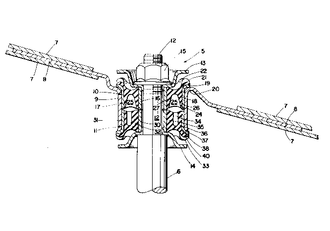
Fig. 1 is an assembly drawing of a shock absorber mount which is made
in accordance with the invention, the two main parts of the mount being
shown in cross-section; and
Fig. 2 is an exploded view of the mount, showing the parts in cross-
section.

2011796
_,
-2--
Detailed Description of Drawing
With~reference to the drawing, there is shown a shock absorbing mount
5 for securing a conventional shock absorber 6 to an automobile frame 7.
The mount 5, when assembled as in Fig. 1, comprises a metal mounting plate
8 which is secured to the adjacent automobile frame 7, the plate 8 having
a vértically disposed, hollow cylindrical housing 9 for receiving a pair of
upper and lower pressed fittings, 10, 11, which surround the upper shaft 12
of the shock absorber 6, and which are held there in the housing by a pair
of vertically spaced metal washers 13, 14 and lock nut 15.
The upper pressed fitting 10 comprises a pair of concentrically dis-
posed metal sleeves 16, 17 which are radially spaced by a resilient, annu-
lar insert 18 which is composed of any suitable resilient elastomeric mater-
ial, e.g. rubber. The upper end 19 of the outer sleeve 17 is curved or
flared outwardly to rest on the adjacent, upper curved end 20 of the housing
9 to limit travel of the upper pressed fitting 10 in the direction of the
lower pressed fitting 11. The upper, radially outermost end 21 of the rub-
ber insert 18 is matingly curved to rest atop the outwardly curved flange
19 of the outer sleeve 17. An annular rubber collar 22, integral with the
rubber insert 18, is formed atop the insert 18 and flange 21, and is provid-
ed with a corrugated outer end 23, for engaging the upper metal washer 13,
depending on the transitional design parameters desired between the upper
washer 13 and upper pressed fitting 10. The vertically lowermost end 24 of
the rubber insert 18 is provided with an inwardly directed, annular void or
cavity 25, the size and shape of which are depended on the shock absorbing
characteristics desired. In this particular instance, the sidewalls 26, 27
of the insert 18 surrounding the annular cavity 25 are tapering and become
thicker in the direction of the upper collar 22.
The lower pressed fitting 11 is similar, in design, to the upper pressed
fitting 10 in that it has a pair of radially spaced inner and outer cylindri-
càl metal sleeves 30, 31, between which is a lower rubber insert 32 which,
likewise, has a corrugated outer rubber collar 33, and an annular void or
cavity 34 which confronts the cavity 25 of the upper pressed fitting 10.
The radially innermost sidewall 35 of the lower cavity 34 is substantially
thicker, in this case, than the radially outermost sidewall 36 of the lower
cavity 34. The lower end 37 of the lower outer sleeve 31 is also curved or
flared outwardly to engage the adjacent lower circular end 38 of the metal

20~1~9G
-
housing 9. So too is the lower end 40 of the lower insert 32 matingly
curved to rest against the flanged end 37 of the lower outer sleeve 31.
It can be appreciated by those skilled in the art, that the upper and
lower pressed fittings 10, 11 will coact to cushion or dampen axial and rad-
ial forces exerted against them. The dampening characteristics of these
fittings can be tuned, as previously mentioned, by varying the composition
of the resilient inserts, or by varying the size or shape of the cavities
in the inserts, or by varying the configuration of the metal sleeeves of
the fittings.
Thus, there has been described a unique shock absorbing mount which is
comprised of a pair of pressed fittings with rubber inserts, which are
mounted together in end-to-end abuting relation. Further, the rubber in-
serts are provided with confronting cavities which are sized and shaped in
accordance with the cushioning or dampening characteristics desired.

Representative Drawing
A single figure which represents the drawing illustrating the invention.
Administrative Status

2024-08-01:As part of the Next Generation Patents (NGP) transition, the Canadian Patents Database (CPD) now contains a more detailed Event History, which replicates the Event Log of our new back-office solution.

Please note that "Inactive:" events refers to events no longer in use in our new back-office solution.

For a clearer understanding of the status of the application/patent presented on this page, the site Disclaimer , as well as the definitions for Patent , Event History , Maintenance Fee  and Payment History  should be consulted.

Event History

Description Date
Inactive: IPC from MCD 2006-03-11
Time Limit for Reversal Expired 1999-05-03
Letter Sent 1998-05-04
Inactive: Adhoc Request Documented 1998-05-03
Letter Sent 1997-05-05
Grant by Issuance 1994-08-02
Application Published (Open to Public Inspection) 1992-04-02
All Requirements for Examination Determined Compliant 1991-05-03
Request for Examination Requirements Determined Compliant 1991-05-03

Abandonment History

There is no abandonment history.

Owners on Record

Note: Records showing the ownership history in alphabetical order.

Current Owners on Record
GENCORP INC.
Past Owners on Record
BRADLEY G. HAMPTON
RICHARD D. HEIN
Past Owners that do not appear in the "Owners on Record" listing will appear in other documentation within the application.
Documents

To view selected files, please enter reCAPTCHA code :


To view images, click a link in the Document Description column. To download the documents, select one or more checkboxes in the first column and then click the "Download Selected in PDF format (Zip Archive)" or the "Download Selected as Single PDF" button.

List of published and non-published patent-specific documents on the CPD .

If you have any difficulty accessing content, you can call the Client Service Centre at 1-866-997-1936 or send them an e-mail at CIPO Client Service Centre.


Document
Description 
Date
(yyyy-mm-dd) 
Number of pages   Size of Image (KB) 
Claims 1993-11-13 2 76
Cover Page 1993-11-13 1 14
Abstract 1993-11-13 1 8
Drawings 1993-11-13 2 53
Description 1993-11-13 3 103
Cover Page 1996-02-09 1 17
Abstract 1994-08-02 1 10
Description 1994-08-02 3 118
Claims 1994-08-02 3 125
Drawings 1994-08-02 2 44
Representative drawing 1999-07-02 1 19
Maintenance Fee Notice 1998-06-01 1 177
Fees 1996-04-15 1 75
Fees 1997-04-17 1 64
Fees 1994-03-30 1 23
Fees 1993-03-24 1 25
Fees 1995-04-18 1 64
Prosecution correspondence 1993-09-15 1 38
PCT Correspondence 1994-05-20 1 35
Courtesy - Office Letter 1991-11-01 1 63
Courtesy - Office Letter 1991-12-13 1 36
Examiner Requisition 1993-08-12 1 48