Language selection

Search

Patent 2042475 Summary

Third-party information liability

Some of the information on this Web page has been provided by external sources. The Government of Canada is not responsible for the accuracy, reliability or currency of the information supplied by external sources. Users wishing to rely upon this information should consult directly with the source of the information. Content provided by external sources is not subject to official languages, privacy and accessibility requirements.

Claims and Abstract availability

Any discrepancies in the text and image of the Claims and Abstract are due to differing posting times. Text of the Claims and Abstract are posted:

  • At the time the application is open to public inspection;
  • At the time of issue of the patent (grant).
(12) Patent: (11) CA 2042475
(54) English Title: DOOR AND WINDOW LATCH
(54) French Title: DISPOSITIF DE VERROUILLAGE POUR PORTE ET FENETRE
Status: Term Expired - Post Grant Beyond Limit
Bibliographic Data
Abstracts

English Abstract


In general, latch devices for sliding patio doors
are complicated and/or intended to lock a door fully closed.
A simple device for latching a sliding door or window partly
or fully open or fully closed includes a track for mounting on
a frame opposite the side edge of a movable door or window
panel; a slide for slidable mounting on the track; a bracket
for mounting on the edge of the panel at the bottom thereof; a
rod pivotally connected to the slide and to the bracket; a
bolt slidable in a recess in the slide body which contains a
spring for biasing the bolt outwardly against teeth on the
track, the teeth normally permitting movement of the slide in
one direction on the track so that the door can be closed but
not opened; and a pin for insertion through the slide into the
bolt to hold the bolt retracted in the slide, so that the door
can move freely between the open and closed positions.


Claims

Note: Claims are shown in the official language in which they were submitted.

THE EMBODIMENTS OF THE INVENTION IN WHICH AN
EXCLUSIVE PROPERTY OR PRIVILEGE IS CLAIMED ARE DEFINED AS
FOLLOWS:
1. A latch device for use on a sliding door or
window of the type including a frame and a panel slidable in
the frame between open and closed positions, comprising track
means for mounting on one side the frame opposite the free
side of the slidable panel in the closed position; slide
means slidable on said track means; arm means pivotally
connecting said slide means to said one side of the slidable
panel; bolt means slidable in said slide means; stop means on
said track means for engagement by said bolt means in a
plurality of positions, said stop means normally permitting
movement of said slide means towards the panel closing
position only; and release means for manually disengaging
said bolt means from said stop means to permit partial or full
opening of the door or window.
2. A latch device according to claim 1, wherein
said stop means includes a plurality of contiguous teeth means
on said track means for releasable engagement by said bolt
means.
3. A latch device according to claim 2, including
slot means in said track means for slidably retaining said
slide means, said slot means containing said tooth means.
4. A latch device according to claim 3, wherein
said slide means includes body means; and spring means in said
- 7 -

body means for biasing said bolt means into engagement with
said tooth means.
5. A latch device according to claim 4, wherein
said release means includes handle means connected to said
bolt means, permitting manual movement of said bolt means out
of engagement with said tooth means against the bias of said
spring means.
6. A latch device according to claim 5, including
pin means insertable into said body means and said bolt means
for releasably retaining the bolt means out of engagement with
said tooth means, whereby the slide means can move freely in
either direction, permitting unimpeded opening and closing of
the door or window.
7. A latch device according to claim 4, wherein
said slot means in said track means is cruciform in cross
section, and one end of said body means is T-shaped in cross
section for limiting movement of the slide means to vertical
sliding when the device is in use.
8. A latch device for use on a sliding door or
window of the type including a frame and a panel slidable in
the frame between open and closed positions comprising track
means for mounting on one side of the frame opposite the free
side of the slidable panel in the closed position; slide means
slidable in said track means; bracket means for mounting on
said free side of the slidable panel proximate the bottom
thereof; rod means for pivotal connection to said slide means
and to said bracket means; bolt means slidable in said slide
- 8 -

means; a plurality of tooth means in said track means
permitting movement of the slide means in one direction;
spring means in said slide means for biasing said bolt means
against said tooth means, whereby the panel can be slid to a
closed position only when said bolt means engages one said
tooth means; handle means on said slide means for retracting
said bolt means into the slide means to release the slide
means for free movement along said track means, whereby the
panel can be slid freely between open and closed positions;
and pin means for insertion through said slide means into said
bolt means to retain the latter in the retracted position.
- 9 -

Description

Note: Descriptions are shown in the official language in which they were submitted.


20~2~7S
This invention relates to a latch device, and in
particular to a sliding door latch.
While the device of the present invention was
originally designed as a latch for a patio or other sliding
door of the type including a fixed panel and a slidable panel,
it will be appreciated that the device can also be used with
other sliding doors and windows.
Often (for example during summer nights), it is
desirable to leave a patio door partly open for ventilation
purposes. However, even if an outer screen door is locked,
such a practice can be quite dangerous.
Sliding door latches already exist. Examples of
such devices are described in United States Patents Nos.
3,471,189; issued to J.M. Ness on October 7, 1969; 3,583,743,
issued to S. Newell on June 8, 1971; 3,630,560, issued to N.C.
Atkins et al on December 28, 1971; 4,295,676, issued to J.A.
Smith on October 20, 1981; 4,318,559, issued to C. Burton on
March 9, 1982; 4,438,640, issued to R.E. Willis on March 27,
1984 and 4,826,225, issued to W.G. Styles on May 2, 1989.
In general, existing devices of the type described
in the above listed patents are intended to permit either
opening or locking of a door in the fully closed position.
Alternatively, existing latches or locks are unduly
complicated in terms of structure or operation. If production
of a device is labour intensive or relies on complicated

- 2~2475
elements, the device becomes so expensive that it is never
mass produced or does not gain public acceptance.
Accordingly, a need still exists for a device which
can be used for latching a sliding door partly open or closed.
An object of the present invention is to meet this need by
providing a latch device for use with a sliding door or window
which is relatively simple in terms of both structure and
operation.
Accordingly, the present invention relates to a
latch device for use on a sliding door or window of the type
including a frame and a panel slidable in the frame between
open and closed positions, comprising track means for mounting
on one side the frame opposite the free side of the slidable
panel in the closed position; slide means slidable on said
track means; arm means pivotally connecting said slide means
to said one side of the slidable panel; bolt means slidable in
said slide means; stop means on said track means for
engagement by said bolt means in a plurality of positions,
said stop means normally permitting movement of said slide
means towards the panel closing position only; and release
means for manually disengaging said bolt means from said stop
means to permit partial or full opening of the door or window.
The invention will be described in greater detail
with reference to the accompanying drawings, which illustrate
a preferred embodiment of the invention, and wherein:

2042475
.
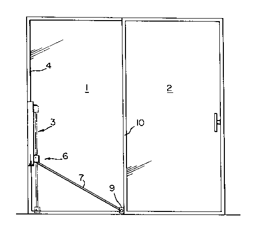
Figure 1 is a schematic front view of a patio door
incorporating a latch device in accordance with the present
invention;
Figure 2 is a perspective view from above of one end
of the latch device of Fig. l;
Figure 3 is a front view of a track used in the
device of Figs. 1 and 2;
Figure 4 is a plan view of the device of Figs. 1
and 2;
Figure 5 is a perspective view from one end of a
slide used in the device of Figs. 1 to 3;
Figure 6 is a partly sectioned front view of the
device of Figs. 1 to 4; and
Figure 7 is a perspective view from above of the
other end of the device of Fig. 1.
Referring to Fig. 1, the latch device of the present
invention is intended for use, inter alia, on a sliding patio
door of the type including a fixed panel 1 and a slidable
panel 2. The principal elements of the device include a track
generally indicated at 3 for mounting a door frame (not shown)
in front of one side 4 of the fixed door panel 1, a slide 6
mounted on the track 3, and an arm or bar 7 pivotally
connected to the slide 6 and to a bracket 9 mounted on the
bottom of the free side 10 of the sliding panel 2 in the
closed position.

204247~
....
As best shown in Figs. 2 to 4, the track 3 is an
elongated, rectangular, plastic bar 12, with a generally
cruciform cross section slot 13 extending the entire length
thereof for slidably receiving the slide 6. The inner arm 14
(Fig. 4) of the slot 13 includes holes 15 at the top and
bottom ends for receiving screws (not shown) for mounting the
track 3 on the door frame. A plurality of teeth 16 defining a
continuous rack are provided between the holes 14. As best
shown in Fig. 6, the teeth 16 define a plurality of contiguous
top inclined ramps 17 and bottom horizontal shoulders 18.
As mentioned above, the slide 6 is slidably mounted
in the track 3. The slide 6 includes a rectangular plastic
body 20 with opposed grooves 21 near one end thereof defining
a T-shaped projection 22 for sliding in the track slot 13. A
bolt 24 is slidably mounted in a bore or cylindrical recess 25
in such one end of the body 20. A helical spring 26 (Fig. 6)
in the recess 25 biases the bolt 24 outwardly so that the
pointed outer end 28 thereof engages the teeth 16. The top of
the outer end 28 (Figs. 5 and 6) of the bolt 24 is flat for
engaging the horizontal teeth shoulders 18. The bolt 24 can
be retracted into the recess 25 and retained therein by a pin
29, which is inserted through aligned holes 30 and 31 (Figs. 5
and 6) in the body 20 and the bolt 24, respectively. The pin
29 is carried by a string 32 connected to the bottom of the
body 20 by a screw 33. A button 34 is slidably mounted on the
body 20 for moving the bolt 24 inwardly against the bias of

204247~
.~
the spring 26. A screw 36 extends through the button 34 and a
slot 37 in the body 20 into the bolt 24. Thus, by sliding the
button 34 away from the projection 22 and the track 3, the
bolt 24 is moved out of engagement with the teeth 16,
S permitting free sliding of the slide 6 in the track 3.
One end 39 of the arm 7 is pivotally mounted in
rectangular recess 40 (Fig. 6) in the bottom of the slide body
20. For such purpose, the screw 33 extends through the body
20 and the top end 39 of the arm 7. As best shown in Fig. 7,
the other end 42 of the arm 7 is pivotally mounted on a bolt
43 extending between the sides 44 of the generally U-shaped
bracket 9. A hole 46 for receiving a mounting screw (not
shown) is provided in the bight or web 47 of the bracket 9.
It will be appreciated that the above described
latch device can be used on virtually any door or window of
the sash-type. By mounting an adapter (not shown) on one end
of a Pierson window for carrying the bracket 9, the device can
also be used on such windows.
In operation, with the sliding panel 2 of the door
closed and the bolt 24 engaging one of the teeth 16, the door
cannot be opened, since any lateral pressure on the panel 2
towards the track 3 would merely press the top of the outer
end 28 of the bolt 24 more firmly against a horizontal
shoulder 18 of the tooth 16. By grasping the slide 6, using
the thumb, the slide 34 can be caused to move away from the
track 3. Thus, the bolt 24 is moved out of engagement with

204247S
the teeth 16, so that the slide can move freely along the
track 3 in either direction to open the door. When free
movement of the door between the open and closed position is
desired, the bolt 24 is retracted, and the pin 29 is inserted
through the aligned openings 30 and 31.
When the door is to be latched partly open, e.g. for
ventilation, the bolt 24 is retracted and the panel 2 is slid
to the desired location. When the slide 34 is released, the
spring 26 pushes the bolt 24 into engagement with one of the
teeth 16. Thus, the door panel 2 can be moved in one
direction only, namely towards the closed position. Any
attempt to open the door will merely result in more secure
latching, i.e. pressing of the bolt 24 against one of the
shoulders 18. Because the block 6 and the slide 34 are on the
frame side remote from the handle side of the sliding panel 2,
the slide 34 cannot be reached from the outside to release the
latch.
It will be appreciated that the track 3 and slide 6
(and, for that matter, the arm 7) can be formed of plastic.
For strength, the arm 7 is preferably formed from a length of
metal tubing. The simplicity of the structure defined herein
lends itself to relatively inexpensive mass production.
Moreover, the device can easily be operated using one hand.
Finally, it will be appreciated that the track 3 can be
mounted on the free edge of the sliding panel, with the
bracket 9 on the door frame.

Representative Drawing
A single figure which represents the drawing illustrating the invention.
Administrative Status

2024-08-01:As part of the Next Generation Patents (NGP) transition, the Canadian Patents Database (CPD) now contains a more detailed Event History, which replicates the Event Log of our new back-office solution.

Please note that "Inactive:" events refers to events no longer in use in our new back-office solution.

For a clearer understanding of the status of the application/patent presented on this page, the site Disclaimer , as well as the definitions for Patent , Event History , Maintenance Fee  and Payment History  should be consulted.

Event History

Description Date
Revocation of Agent Requirements Determined Compliant 2020-09-01
Inactive: Expired (new Act pat) 2011-05-13
Inactive: IPC from MCD 2006-03-11
Grant by Issuance 1996-07-16
Application Published (Open to Public Inspection) 1992-11-14
Request for Examination Requirements Determined Compliant 1992-10-14
All Requirements for Examination Determined Compliant 1992-10-14
Small Entity Declaration Determined Compliant 1991-05-13

Abandonment History

There is no abandonment history.

Fee History

Fee Type Anniversary Year Due Date Paid Date
MF (patent, 7th anniv.) - small 1998-05-13 1998-05-12
MF (patent, 8th anniv.) - small 1999-05-13 1999-04-23
MF (patent, 9th anniv.) - small 2000-05-15 2000-05-11
MF (patent, 10th anniv.) - small 2001-05-14 2001-05-09
MF (patent, 11th anniv.) - small 2002-05-13 2002-05-09
MF (patent, 12th anniv.) - small 2003-05-13 2003-05-09
MF (patent, 13th anniv.) - small 2004-05-13 2004-04-20
MF (patent, 14th anniv.) - small 2005-05-13 2005-05-03
MF (patent, 15th anniv.) - small 2006-05-15 2006-05-03
MF (patent, 16th anniv.) - small 2007-05-14 2007-04-24
MF (patent, 17th anniv.) - small 2008-05-13 2008-05-05
MF (patent, 18th anniv.) - small 2009-05-13 2009-05-12
MF (patent, 19th anniv.) - small 2010-05-13 2010-03-11
Owners on Record

Note: Records showing the ownership history in alphabetical order.

Current Owners on Record
PIERRE VEILLETTE
Past Owners on Record
None
Past Owners that do not appear in the "Owners on Record" listing will appear in other documentation within the application.
Documents

To view selected files, please enter reCAPTCHA code :


To view images, click a link in the Document Description column. To download the documents, select one or more checkboxes in the first column and then click the "Download Selected in PDF format (Zip Archive)" or the "Download Selected as Single PDF" button.

List of published and non-published patent-specific documents on the CPD .

If you have any difficulty accessing content, you can call the Client Service Centre at 1-866-997-1936 or send them an e-mail at CIPO Client Service Centre.


Document
Description 
Date
(yyyy-mm-dd) 
Number of pages   Size of Image (KB) 
Abstract 1993-11-02 1 21
Claims 1993-11-02 3 78
Drawings 1993-11-02 3 74
Description 1993-11-02 6 186
Description 1996-07-15 6 201
Abstract 1996-07-15 1 23
Claims 1996-07-15 3 86
Drawings 1996-07-15 3 66
Representative drawing 1999-07-05 1 8
Fees 2003-05-08 1 23
Fees 1998-05-11 1 30
Fees 2002-05-08 1 25
Fees 2001-05-08 1 25
Fees 1999-04-22 1 29
Fees 2000-05-10 1 27
Fees 2004-04-19 1 30
Fees 2005-05-02 1 22
Fees 2006-05-02 1 22
Fees 2007-04-23 1 22
Fees 2008-05-04 1 24
Fees 2009-05-11 1 23
Fees 1997-05-06 1 28
Fees 1996-05-02 1 31
Fees 1995-04-02 1 29
Fees 1994-04-19 1 28
Fees 1993-03-22 1 18
PCT Correspondence 1996-05-02 1 30
PCT Correspondence 1995-10-01 2 87
Prosecution correspondence 1992-10-13 1 25
Courtesy - Office Letter 1992-11-16 1 29