Note: Descriptions are shown in the official language in which they were submitted.
This invention relates to an improved electrical
appliance wall plug for use with a split circuit duplex
wall outlet.
Commonly found in residential kitchens/ the split
circuit duplex outlet provides power for up to two separate
appliances WhiCh consume relatively large amounts of power,
such as deep fryers, electric kettles, griddles, broilers
and ovens, each having power requirements of up to 1500
watts.
Conventionally, kitchen appliances are designed for
use with single circuit 115 volt alternating current
outlets, and utilize a single 2 or 3 pronged male plug and
a 2 or 3 wire power cord. Certain appliances, such as
those mentioned above, can underperform at wattages
limited, conventionally, to 1500 watts and may benefit
substantially in their operation by an increase in power to
~etween 1500 and 3000 watts. Current building codes
require all kitchen counter outlets to be split circuit
duplex wall receptacles providing two 1500 watt circuits
operating at the same frequency but 180 degrees
out-of-phase, WhiCh can accommodate plugs having 6 male
prongs comprising 2 sets of 3 prongs, namely a "hot" or
power lead (normally red or black), a neutral (white)/ and
a ground (green), and thereby supply up to two 1500 watt
115 volt circuits (3000 watts) or one 3000 watt 230 volt
circuit to a single specifically designed appliance.
Need has existed arising from the requirement for
flexi~ility in outlet voltages for either 115 or 230 volts,
without altering the household wiring connected to the
split circuit duplex wall outlet, and to accommodate this
need, prior art teachings, such as United States patent to
Praml, 4,019,797 dated April 16, 1977, have described plugs
comprising two halves in a duplex wall plug which may
operate to provide either standard 115 volt or 230 volt
power, by substituting plugs having appropriate electrical
connections.
One of the improvements comprised in the present
invention involves the incorporation of a split circuit
indicator light, which visually distinguishes between
single and split circuit household duplex receptacles which
are unidentifiable otherwise.
Another improvement involves the incorporation of
switch means in the plug operat:ing to selectively utilize
either both or one side only o~ a split circuit power
supplyt thereby allowing the user the flexibility of access
to 3000 watts or 1500 watts of power from a split circuit
outlet. Further to this, the switch can also limit power
to 1500 watts from a single circuit outlet found in
~itchens wired prior to the current building codes.
Accordingly, it is the principle objective of this
invention to provide a plug assembly including visual
indication means, such as an indicator light, to
distinguish between split circuit and single circuit
kitchen duplex outlets.
-- 2 --
~2~
It is another objective oE this in~ention to provide a
plug assembly for use in combination with (1) an identiEied
split circuit duplex outlet having switch means to
selectively conEigure the plug for low power single circuit
operation or high power plug configurations and (2) an
identified single circuit duplex outlet having switch means
to selectively configure the plug to limit it to single
circuit operation.
It is a further object of the invention to provide an
apparatus of the type described, which is characterized by
a simplicity of design and possesses the necessary
ruggedness for practical and reliable use.
Additional objects and advantages will become apparent
from the following detailed description taken in
conjunction with the accompanying drawings and appended
claims in whicho
Figure 1 is a schematic oE a split wire circuit of a
type in common use in residences for connection to duplex
wall outlets.
Figu~e 2 is a plan view, partly in schematic, of a
plug ass~m~ly in accordance with the preferred embodiment
of the present invention.
Figure 3 is a side view of the plug assembly of Figure
2.
Figure 4 is a plan view depicting the housing of the
plug assembly of Figure 2.
Similar numerals of reference designate corresponding
parts in the drawings.
Referring to the drawings and with particular
reference to Figure 1, a schematic showing of a split wire
circuit o~ a type conventionally available in modern
residential construction is depicted, in which a grounded
duplex electrical outlet 10, comprising a pair of outlets
11 and 11', to which are connected, respectively, hot leads
12 and 13 designated respectively as "red" and "black", and
connected to the power supply panel through a single throw
230 volt ~reaker 14. Female connectors 15 and 16 are
positioned in the insulated housing 17 at opposite ends, as
depicted in Fig. 1 to which the hot leads 12 and 13 are
connected. Neutral connectors 18 and 19 are spacially
aligned conventionally with hot wire connectors 15 and 16
and are connected in parallel to a neutral lead 1~,
designated "white" in Fig~ 1. Grounding COnneGtOrS 20 and
21 centered on the housing 17/ are electrically connected
to ground 22, Fig. 1.
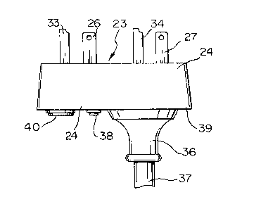
Referring to Fig. 2, a preferred embodiment of the
plug assembly of the invention is depicted, adapted to
terminate the electrical cords from electrical appliances
or other load-bearing devices. The plug assembly generally
designed 23 comprises an insulated housing 2~ of
non-conductive plastic, preferably of a phenolic resin
conforming to Underwriters' Laboratories Inc.
specifications for 230 volts. The molded housing 24 is of
generally rectanqular box-like hollow configuration,
constituted to hold the electrically operative elements in
rigid configuration, and can be either two-part
construction or unitary. Prongs or blades generally
indicated at 25 project from the face oE the housing 24, as
indicated in Fig. 3, to register with the connectors of the
outlet 10, Fig. 1, as will now be described.
Referring again to Fig. 2, the prong 25 includes power
prongs 26 and 27 are aligned on the face of the housing 24
with the hot connectors 15 and 16 respecti~ely of Fig. 1,
and hOt leads 28 and 29, designated "red" and "black", Fig.
2, connect electrically with the power prongs 26 and 27.
Neutral prongs 30 and 31 are similarly aligned on the
housing 24 to register with neutral connectors 18 and 19,
FigO 1, and are electrically connected to a common neutral
lead 32, designated "white", Fig. 2. Ground prongs 33, 34,
normally of u-ground type, are positioned centrally of the
housing 24, and aligned with gr.ound connectors 20 and 21,
Fig. 1, and are electrically connected to the common ground
wire 35, designated "green", Fig. 2.
The prongs or blades 25 are normally formed of ~rass
or other conducting metal, and extend through the face o-f
the housing 24, into the housing interior and employ
conventional electrical connecting means such as screw
terminals ~not illustrated) for connection of the
-- 5 --
. ~! ,., ~ ~ . ;
'' ,
2, ~
electrical leads 28, 29, 32S and 35 passing outwardly of
the housing 24 at the insulating nipple 36 projecting Erom
the rear surface of the housing 24, Fig. 3, and are
normally enclosed within a common conduit or ca~le 37,
leading to
the load-~earing appliance.
Referring Eurther to Figs. 2 and 3, a switch 38 is
included on one of the power leads 28, 29, selectively to
open one of the circuits, the second circuit eemaining
closed, as depicted in Fig. 2. Switch 38 desirably of the
slide or throw type, is depicted mounted rigidly on the
back surface 39 of the housing 24.
Further reference to Figs. 2 and 3 discloses an
indicator light 40, electrically connected across the hot
connectors 25 and 26, Fig. 2, and will ~e similarly mounted
rigidly on the back surface 39 of the housing 24, Fig. 3.
The indicator light will accommodate 250 volts, as the
maximum voltage potential between two halves of the split
voltage supplied to the plug asse~bly.
In operation:
(1) with the plug inserted into a split circuit outlet the
indicator light 40 will respond to visually indicate that a
split circuit outlet has been utilized and two 15 amp
circuits are available for useO With the switch 38 closed
~oth 15 amp circuits are availa~le for use as a high power
setting and with the switch 38 open only one 15 amp circuit
is available for use as a low power setting.
(2) with the plug inserted into a single circuit outlet
the indicator light ~0 will not respond and indicate that a
single circuit outlet has been utilized and only one 15 amp
circuit is available ~or use. This limits the switch
38 to the open position only, providing Eor use in the low
power setting exclusively.
The foregoing system offers the following advantages.
(1) a plug assembly for use in combination with a duplex
outlet with an indicator light that visually identifies
whether a split circuit or single circuit outlet has been
utilized and whether both high and low power settings are
available, and
(2) a switch to allow both high and low power settings
when used in combination with a split circuit outlet and to
allow usage in the low power setting only, when used in
combination with a single circuit outlet.
The present invention is not limited to the specific
embodiment disclosed by way of example. It will be
appreciated that a plug of the disclosed embodiment can be
used with split wire direct current circuits, as well as
the alternating current circuit shown herein. It will be
understood that the scope o~ the invention is only limited
as defined in the appended claims.