Note: Descriptions are shown in the official language in which they were submitted.
:~ 2~4~'73~
Device for severing the pubis of the carcass of a slaughtered
animal.
BACKGROUND OF THE INVENTION
The invention relates to a device for severing the pubis
of the carcass of a slaughtered animal, in particular a pig,
comprising a positioning element which is fitted at the end
of an elongated carrier and is to be introduced through the
anus into the rectum, a rotary-driven cylindrical first
cutting element which is fitted concentrically around it and
is displaceable in the lengthwise direction, and which has
an end cutting edge describing a circular movement for
cutting loose the rectum, and a blade-type cutting element
for severing the pubis, which are combined to a functional
unit which can be moved in its entirety to and from the
carcass, and in which the movements of the positioning
element can be controlled independently of those of the other
elements.
DESCRIPTION OF THE PRIOR ART
.~
Such a device is known per se from NL-A-8602219
(corresponding to EP-A-0,258,939).
Although this known device operates satisfactorily in
practice, sometimes the problem is encountered that the
~ position of the tail of the carcass is not precisely defined
:~ while the operation is being carried out and also that the
depth over which the cylindrical cutter penetrates into the
25 carcass depends on the position of the carcass relative to
the device and is sometimes tGo great, which leads to damage
to the rectum with the escape of faeces.
SUMMARY OF THE INVENTION
The ob~ect of the invention is to eliminate these
problems, and this object is achieved according to the
invention by a pressure element which is situated next to the
2~2~ll3~
- 2
cylindrical cutter, at the end of a guided carrier movable
parallel to the direction of movement of said cutter, which
pressure element has a U-shaped pressure stirrup for gripping
around the tail and pressing it down.
Preferably this pressure stirrup is accommodated inside
a carrying stirrup about an axis of rotation which is situated
at right angles to the longitudinal axis of the carrier, is
provided with end edges flanged downwards, and is
springtensioned away from the carrier.
In a preferred embodiment two pressure plates are fitted
on the carrier, enclosing the pressure stirrup between them
and situated at right angles to the direction of movement
thereof.
Preferably fitted on the elongated carrier which is
guided in the lengthwise direction inside the functional unit
is a first element which moves along with the part of said
carrier lying inside the unit and indicatss the position
thereof relative to the unit, and which forms a reference
limiting the stroke of the positioning element relative to the
unit.
DESCRIPTION OF THE DRAWINGS
Figure 1 is a side view of the functional cutting unit as
known from NL-A-8602219;
Figure 2a is a side view of the stirrup used according to
the invention, with tail displacer and pressure plates;
Figure 2b is a front view of these elements;
Figure 2c is a top view of these elements;
Figure 3 is a schematic cross-section of a part of the
functional unit to illustrate the control achieved with
carrier and pressure plates;
Figures 4a to 4f are side views, in partial section of
the stirrup in accordance with the present invention, in
progressive stages of operation.
DESCRIPTION OF A PREFERRED EMBODIMENT
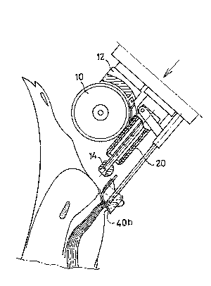
The functional unit 2, which is the sub~ect of an
apparatus such as that described in NL-A-86022~9, comprises a
frame 4 in which a rotary-driven, blade-type cutter 10,
2~27~
....
2a
accommodated in a housing 12, i~ ~upported ~o that it m v
/
"'''""'' ""''' ;"' ~ .
2 0 ~ 2 ~ 3 Q
in the direction of the arrows 6 under the influence of a
working cylinder 8. Below this cutter 10 is a spherical
positioning and shut-off element 14 which is to be introduced
into the rectum of the carcass, and which is fitted on the
end of the elongated carrier 16 and can also be moved in the
direction of the arrows 6, independently of the movement o~
the cutter 10. Placed concentrically around the carrier 16
is a cylindrical cutter 18, which is accommodated in a
protective sleeve 20; cutter and sleeve are fixed to the
frame 4 and thus move along with it. The movement of the
carrying rod 16 is transmitted to the rod 22 which lies in
line with it (see Figure 3) and which bears at the rear end
a stop 24 which is positioned at right angles to said rod,
and the function of which will be explained in greater detail
below.
The movement of the carrying rod 16, and thus of the rod
22, is brought about by means of a suitable control by an air
cylinder (not shown).
Up to this point the device according to the invention
corresponds by and large to the one which is known from NL-A-
8602219. A major difference from this known device is,
however, the presence of a carrier 28 which is mounted in the
frame 4 so that it is slidable in the direction of the arrows
6 and which comprises two rods 26a, 26b which are connected
to a rod 30 which is guided in the frame on the righthand
side and thus follows the movements of the carrier 28. This
rod 30 bears two stops: a first, indicated by 32 and
interacting with the stop 24 on the rod 22, and a second,
indicated by 34 and forming a run-on cam. This run-on cam 34
interacts with the control roller 36 of a switch 38 which is
connected to the carrying rod 16 of the positioning ele~ent
14 and, if operated, stops the movement thereof. The object
of the two stops and the way in which they work will now be
explained in further detail below.
As Figures 2a, 2b and 2c show, the carrying rods 26a,
26b each bear on their front end a pressure plate 40a, 40b,
which - as will be explained below - in the end come to rest
against the carcass on either side of the anus when the
cutting unit is moved towards the carcass. They also carry
~2~3~
by means of the connecting plates 42a, 42b a U-shaped stirrup
44 in which a second U-shaped stirrup 46 is accommodated, the
legs 48a, 48b of which are connected to the bearing plates
42a, 42b by means of connection plates 50a, 50b so that they
pivot about axes 52a, 5~b. The front ends 54a, 54b of the
legs 48a, 48b are bent downwards and two tension springs 56a,
56b pull the stirrup 46 in the direction of the arrow 58.
The device largely works in the same way as the known
device, although as a result of the presence of the
displaceable tail pressure stirrup 46 and the control
functions performed by its carrier there are differences. The
way in which it works is explained with reference to Figures
4a to ~f.
These figures show a pig carcass 70, suspended by the
hind legs 72, with the flank 74, anus 76, rectum 80, backbone
82 and tail 84. Figure 4a shows the situation in which the
functional unit 2 is being moved in the direction of the
arrow 86 towards the carcass. Figure 4b shows how this
movement is stopped when the unit 2 is a certain distance
from the carcass and has reached the position shown; the
pressure plates 40a, 40b then lie against the carcass, and
the stirrup 46 takes the tail into a fixed, downward-pointing
position, so that the tail cannot impede the remaining
operations. Through a movement in the direction of the arrows
88 and 90, indicated in Figure 4c, the positioning and shut-
off ball 14 seeks the anus and when it has found it pene-
trates - driven by an air cylinder which is not shown -
through the rectum until it reaches the position shown in
Figure 4d. The distance over which the ball 14 penetrates
into the rectum i5 determined by the distance which the
carrier 28 has been pushed back into the unit; the stop 32
(Figure 3) in this case moves to the right, while the stop
34 connected to the carrying rod 16 moves to the left during
the movement of the positioning ball until the stop 24 runs
up against the stop 32. This stroke of the positioning ball
14 is shown by 'b' in Figure 4e. Finally, the whole unit (see
Figure 4e) with the rotary-driven cylindrical cutter 18 and
the rotary-driven blade cutter 10 moves forward over a
distance which is indicated by 'a' in Figure 4e and is also
20~2 13~
determined by the distance over which the carrier 28 is
pushed back into the unit. For, with this carrier the
stopping cam 34 also moves to the right; this stopping cam
interacts, as already explained, with the feeler 36 which
moves along with the unit to the left and is connected to a
switch (not shown) which when the feeler 36 runs up against
the projection 34 stops the movement of the unit, which has
then reached the position shown in Figure 4e. Finally, the
cutting blade 10 with its carrier lOa moves forward in the
direction of the arrow 90, and in the process cleaves the
pubis 78.
The different component parts are then returned to their
initial position.