Note: Descriptions are shown in the official language in which they were submitted.
2042949
-1 -
PROCESS AND APPARATUS FOR
PRODUCING LIQUID CRYSTAL PANEL
FIELD OF THE INVENTION AND RELATED ART
The present invention relates to a process and
an apparatus for producing a liquid crystal panel,
particularly a process and an apparatus for producing a
liquid crystal panel by injecting a ferroelectric
liquid crystal into a liquid crystal cell.
In a conventional process for filling a liquid
crystal panel with a liquid crystal known heretofore as
disclosed, e.g., by Japanese Patent Publication (JP-B)
Sho. 60-49889, a liquid crystal panel and a liquid
crystal reservoir are placed in a pressure-resistant
container or chamber, the pressure in the container is
reduced, the injection port of the liquid crystal panel
is dipped in the liquid crystal reservoir, and then the
pressure in the container is restored to the
atmospheric pressure to fill the liquid crystal panel
with the liquid crystal.
However, in case where the above method of
liquid crystal injection is used for filling with a
ferroelectric liquid crystal material having a higher
viscosity than a twisted nematic liquid crystal
material, a large amount of the liquid crystal as large
as ten times the amount filled in the liquid crystal
panel is attached to a portion around the injection
~ -2- 20~2949
port of the liquid crystal panel. Accordingly, a large
amount of the liquid crystal is lost and a larger load
is required for a troublesome washing step so as to
remove the excessive liquid crystal attached to around
the injection port.
SUMMARY OF THE INVENTION
An object of the present invention is to
provide a process and an apparatus which are optimum
for producing a liquid crystal panel by injection of a
ferroelectric liquid crystal panel through an
improvement of such a conventional method of injecting
a liquid crystal material into a liquid crystal panel
to reduce the loss of liquid crystal material and the
load of the washing as a post-step.
According to an aspect of the present
invention, there is provided a process for producing a
liquid crystal panel comprising the steps of:
placing a blank liquid crystal panel having an
injection port and a liquid crystal reservoir
containing a liquid crystal within a vacuum
environment,
causing a transfer member moving between the
liquid crystal reservoir and the liquid crystal panel
to carry a portion of the liquid crystal in the liquid
crystal reservoir,
applying the liquid crystal carried on the
2042949
transfer member to the injection port of the liquid
crystal panel, and
placing the injection port of the liquid
crystal panel within an environment of atmospheric
5 pressure.
According to another aspect of the present
invention, there is provided a process for producing a
liquid crystal panel comprising: applying a liquid
crystal contained in a liquid crystal reservoir to an
injection port of a blank liquid crystal panel in a
vacuum space and then restoring the pressure of the
vacuum space to an atmospheric pressure to inject the
liquid crystal into the liquid crystal panel; wherein a
transfer member moving between the liquid crystal
reservoir and the liquid crystal panel is used to carry
the liquid crystal within the liquid crystal reservoir
and then apply the liquid crystal to the injection port
of the liquid crystal panel.
According to a further aspect of the present
invention, there is provided an apparatus for producing
a liquid crystal panel, comprising: a vacuum chamber,
and a liquid crystal panel having an injection port and
a liquid crystal reservoir containing a liquid crystal
disposed within the vacuum chamber so that a portion of
the liquid crystal contained in the liquid crystal
reservoir is applied to the injection port of the
liquid crystal port and then the vacuum chamber is
2042949
--4--
restored to atmospheric pressure, wherein the apparatus
further comprises a transfer member moving between the
liquid crystal reservoir and the liquid crystal panel
to carry the portion of the liquid crystal within the
liquid crystal reservoir and then apply the portion to
the injection port of the liquid crystal panel.
These and other objects, features and
advantages of the present invention will become more
apparent upon a consideration of the following
description of the preferred embodiments of the present
invention taken in conjunction with the accompanying
drawings .
BRIEF DESCRIPTION OF THE DRAWINGS
Figure 1 is a schematic view for illustrating
a first embodiment of the process and apparatus for
producing a liquid crystal panel according to the
present invention.
Figure 2 is a schematic view for illustrating
a second embodiment of the process and apparatus for
producing a liquid crystal panel according to the
present invention.
Figures 3A - 3C are perspective views each
illustrating the shape of a part for transferring a
liquid crystal of a transfer member.
Figures 4A and 4B are partial enlarged views
each showing a part for applying a liquid crystal of a
- -5- 20~2949
transfer member.
DESCRIPTION OF THE PREFERRED EMBODIMENTS
In a preferred embodiment of the present
invention, a transfer member having a transfer part
(end) with a length which is longer than the length of
an injection port of a liquid crystal panel and shorter
than the face of the liquid crystal panel having the
injection port is used. Within a vacuum chamber, the
transfer part of the transfer member is dipped in a
liquid crystal reservoir, is pulled up from the liquid
crystal reservoir to apply the liquid crystal within
the liquid crystal reservoir onto the transfer member
and is then brought in close proximity to or in contact
with the injection port of the liquid crystal panel so
as to transfer the liquid crystal to the injection
port. As a result, the injection port of the liquid
crystal panel can be completely covered by the liquid
crystal with minimum attachment of the liquid crystal
to an unnecessary part of the liquid crystal panel.
Then, the vacuum chamber is restored to the atmospheric
pressure to inject the liquid crystal into the liquid
crystal panel.
If the temperatures of the respective members
are controlled, the above-mentioned transfer step can
be further stabilized. More specifically, it is
preferred to heat the transfer member, the injection
~~ -6- 20429~9
port of the liquid crystal panel and the liquid crystal
reservoir, so as to provide a temperature T1 for the
liquid crystal in the liquid crystal reservoir, a
temperature T2 for the transfer member and a
temperature T3 for the injection port of the liquid
crystal panel, satisfying the relationship of:
T1 _ T3 _ T2
The above temperature relationship is
desirable for the following reasons.
A ferroelectric liquid crystal generally has a
high viscosity, so that it is desirable to utilize a
temperature difference between two members in
transferring or applying the liquid crystal to control
the movement of the liquid crystal.
Firstly, a step of transferring a liquid
crystal in a liquid crystal reservoir to a transfer
member is explained. A liquid crystal material is
generally a mixture comprising many mesomorphic
compounds, so that it is necessary to prevent a change
or localization in composition within the liquid
crystal reservoir. For this reason, it is desirable to
heat the liquid crystal reservoir to an elevated
temperature to lower the viscosity of the liquid
crystal in the reservoir.
In case of transferring the liquid crystal to
the transfer member, it is possible to transfer the
liquid crystal in a necessary minimum amount if the
~ _7_ 2042949
relationship of T1 > T2 is satisfied between the
temperature T1 of the liquid crystal reservoir and the
temperature T2 of the transfer member. If a condition
of T1 < T2 stands reversely, an excessive amount of
liquid crystal is transferred to the transfer member,
so that it becomes necessary to effect a cleaning of
the transfer member or the liquid crystal is liable to
drop during the movement of the transfer member.
Next, a step of applying the liquid crystal to
the liquid crystal panel from the transfer member is
explained.
It is desired that as large a proportion as
possible of the liquid crystal transferred to the
transfer member is applied to the liquid crystal panel.
This is because, if a large amount of the liquid
crystal remains attached to the transfer member, a
cleaning operation can be required for removing the
liquid crystal prior to a subsequent transfer cycle.
Further, unless the injection port of the liquid
crystal panel is completely covered with the liquid
crystal, the injection of the liquid crystal fails.
For the above reason, it is desired that a relationship
of T3 > T2 is satisfied between T2 and the temperature
T3 of the injection port of the liquid crystal panel.
Under a higher injection temperature, i.e., a
higher T3, it is possible to prevent the invasion of
air bubbles at a higher degree because of a lower
-8- 2042949
viscosity, so that a higher T3 is generally preferred.
Too high T3 however leads to a problem of dropping of
the liquid crystal from the liquid crystal panel.
Therefore, it is desired that the upper limit of T3 is
set to T1 to satisfy the relation of T1 ~ T3.
Consequently, it is desirable to set T1, T2
and T3 so as to satisfy the relationship of T1 > T3 _
T2 .
In the case where the present invention is
applied to a ferroelectric liquid crystal material, it
is desired to control the temperatures T1, T2 and T3
corresponding to the phase transition temperatures of
the ferroelectric liquid crystal. The ferroelectric
liquid crystal can be selected from a large scope
without particular restriction. For example,
(1) if a ferroelectric liquid crystal has a phase
transition series of Crystal ~ SmC* ~ -SmA e-~ Ch. ~ -
Iso. (SmC*: chiral smectic phase, SmA: smectic A phase,
Ch.: cholesteric phase, Iso.: isotropic phase), or a
series of Crystal ~SmC*~ ~Ch.- ~ Iso., it is
preferred to effect a temperature control so as to
satisfy a relationship of T1 > T3 > (cholesteric phase
temperature) > T2, and
(2) if a ferroelectric liquid crystal has a phase
transition series of Crystal-~ ~SmC* ~SmA ~-~Iso. or
Crystal-~ ~Sm3~-~ SmC*~-~ Iso. (Sm3: a smectic phase
(un-identified)), it is preferred to effect a
204294~
g
temperature control so as to satisfy a relationship of
T1 2 T3 > (isotropic phase temperature) > T2.
Consequently, it is preferred to effect a temperature
control so as to satisfy a relationship of T1 > T2 > T4 (a
temperature providing a higher temperature phase than
SmC*) 2 T3. This is because a ferroelectric liquid
crystal does not generally show a substantial fluidity
and is not suitable for transfer and application in
SmC* phase or in a lower temperature phase than SmC*.
Such a temperature control can be effected by a heater,
a thermistor and/or a temperature controller.
The transfer member may preferably have an end
face having a length L2 for applying a liquid crystal
to the injection port of the liquid crystal panel
satisfying the relationship of L3 < L2 < L1 with
respect to the liquid crystal panel which has a face
including the injection port and having a length L1 and
has the injection port having a length L3. This is
because, in case of L1 < L2, the liquid crystal
attached to one or both sides is not applied to the
liquid crystal panel but remains on the transfer
member, thus resulting in difficulties such that it
drips or requires a cleaning step and an unnecessary
amount of liquid crystal is attached to a side face of
the liquid crystal panel. On the other hand, in case
of L2 < L3, the injection port of the liquid crystal
panel is not sufficiently covered with the applied
20~2949
, o
liquid crystal, thus allowing air bubbles to enter the
liquid crystal panel.
Figures 3A - 3C respectively show some shapes
of a part 8 (Figure 3A) or parts 8 (Figure 3B and 3C)
carrying and applying a liquid crystal of the transfer
member 5 and particularly embodiments of the parts 8
(Figures 3B and 3C) for simultaneously transferring the
liquid crystal to a plurality of liquid crystal panels
held in a cassette.
Figures 4A and 4B are partially enlarged
illustrations of two type of concavities formed at the
top of a part 8 for transferring a liquid crystal for
illustrating the operation of the part 8 corresponding
to one shown in Figure 3B. The end face of a liquid
crystal panel having an injection port is formed by
bonding a pair of glass or plastic substrates after
alignment at their ends which have been optionally
formed by cutting. Particularly, in the case where the
end face is formed by cut ends, for example, an
injection port is positioned inward from utmost ends of
the substrates, and it is preferred that the part 8
carrying and applying the liquid crystal of the
transfer member is concave as shown in Figures 4A and
4B. Such a concavity has a function of automatically
aligning the end face of the liquid crystal panel at
the time of applying the liquid crystal to the liquid
crystal panel. The concavity also has a function of
- -11- 2042949
effectively retaining the liquid crystal to prevent the
liquid crystal from dripping.
The shapes of the transfer member and the end
face thereof for transferring the liquid crystal are
not restricted to those specifically shown in the
drawings.
The pressure within the vacuum chamber after
evacuation and for the liquid crystal transfer
operation may desirably be 1.0x10⁻³ torr or below,
preferably 1.0x10⁻⁵ torr or below.
As described above, according to the present
invention, the injection of a liquid crystal into a
liquid crystal panel is effectively carried out with
minimum loss of the liquid crystal and alleviation of
the load of washing of the liquid crystal as a post-
treatment, and also the injection of a ferroelectric
liquid crystal having a high viscosity can also be
effected easily.
Hereinbelow, the present invention will be
explained with specific examples.
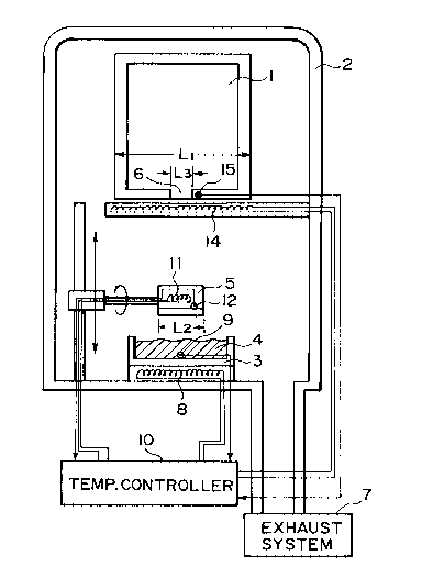
Example 1
Figure 1 is a schematic view of an embodiment
of the apparatus for producing a liquid crystal panel
according to the present invention.
Referring to Figure 1, the apparatus includes,
within a vacuum chamber 2, a liquid crystal panel 1
having at least one injection port 6, a liquid crystal
-
-12- 2 0 4 2 9 4 9
reservoir 3 containing a liquid crystal 4, and a
transfer member S which is moved between the liquid
crystal reservoir 3 and the liquid crystal panel 1 for
carrying a portion of the liquid crystal 4 in the
liquid crystal reservoir 3 and applying the carried
portion of the liquid crystal to the injection port 6
of the liquid crystal panel. In this instance, the
liquid crystal panel 1 is formed to have an end face
having a length L1 and including the injection port 6
having a length L3, and the transfer member 5 is
constituted to include an end face having a length L2
for applying the liquid crystal to the injection port
of the liquid crystal panel, satisfying the
relationship of L3 < L2 < L1.
In a specific example, these lengths were set
to L1 = 275 mm, L2 = 100 mm, and L3 = 60 mm. The
liquid crystal 4 was a ferroelectric liquid crystal
("CS-1014", available from Chisso K.K.) showing the
following phase transition series:
54.5 C 68.5 C 80.0 C
Cryst.~-- SmC* ~ - SmA ~ ~ Ch.~ -Iso.
The temperature T1 of the liquid crystal 4 in the
liquid crystal reservoir 3, the temperature T2 of the
transfer member 5 and the temperature T3 at the
injection port of the liquid crystal panel 1 were set
to T1 = 90 C, T2 = 25 C, and T3 = 75 C. The
transfer member 5 was formed to have liquid crystal
-13- 2042949
application parts 8 shown in Figure 3C and having a
concavity as shown in Figure 4B.
In preparation of a liquid crystal panel by
using the above-mentioned apparatus, an exhaust system
7 conductively connected to a vacuum chamber 2 is first
operated to evacuate the vacuum chamber 2 and the
inside of the liquid crystal panel 1 contained therein.
During the exhaustion step, the liquid crystal 4 in the
liquid crystal reservoir 3 is heated by a heater 8 for
the liquid crystal reservoir to a temperature (T1 = 90
C) for providing an isotropic phase, the end face
having the injection port 6 of the liquid crystal panel
1 is heated by a heater 14 for the liquid crystal panel
to a temperature (T3 = 75 C) providing the cholesteric
phase of the liquid crystal, and the transfer member 5
is heated to a temperature (T2 = 25 C) by a heater 11
for the transfer member. After a sufficient degree of
evacuation to a pressure (e.g., 3x10⁻⁵ torr) within the
vacuum chamber 2, the transfer member 5 is partly
dipped in and then pulled out of the liquid crystal
reservoir 3 to carry a portion of the liquid crystal 4.
Then, the transfer member 5 is turned up side-down so
as to direct the dipped end upward and then further
moved upward to contact the injection port 6 of the
liquid crystal panel 1, so that the injection port 6 is
completely covered by the carried and transferred
portion of the liquid crystal 4. Then, the vacuum
-14- 2042949
chamber 2 is restored to the atmospheric pressure to
effectively inject the liquid crystal inside the liquid
crystal panel 1.
In this way, in a specific example, the
attachment of the liquid crystal to an unnecessary part
other than the injection port 6 was minimized.
The heat generation from the heater 8 for the
liquid crystal reservoir, the heater 11 for the
transfer member and the heater 14 for the liquid
crystal panel was controlled by annexed thermistors 9,
12 and 15, respectively, and a temperature controller
1 0 .
Example 2
Figure 2 is a schematic view of another
embodiment of the apparatus for producing a liquid
crystal panel according to the present invention. In
Figure 2, like parts are denoted by like references
numerals as used in Figure 1.
More specifically, Figure 2 shows an
embodiment of the apparatus wherein a transfer member
5a after dipping for carrying a portion of a liquid
crystal 4 within the liquid crystal reservoir 3 is
moved to the injection port 6 of the liquid crystal
panel 1 for transfer of the liquid crystal without
turning or rotation thereof.
In this example, as the transfer member 5 is
not turned or rotated after dipping, the relative
-15- 2042949
positions or directions of the liquid crystal
reservoir, and the liquid crystal panel are different
from those in Example 1. However, other structures or
members and operation thereof are similar to those in
Example 1. In Figure 2, the heaters, thermistors and
temperature controller are omitted from showing.
In a specific example according to this
example, the liquid crystal panel was also effectively
filled with the liquid crystal.
Comparative Example 1
Liquid crystal panels were prepared similarly
as in Example 1 except that L1, L2 and L3 were set to
L3 < L1 < L2-
Because of the relation of L1 < L2, a portion
of the liquid crystal carried on the transfer memberand not transferred to a liquid crystal panel remained
at both ends of the transfer member. As a result,
after several times of the repetitive transfer
operation, the liquid crystal was caused to drip, so
that a cleaning of the transfer member and inner parts
of the vacuum chamber was necessary. Further, as a
part of the liquid crystal was attached to side faces
of liquid crystal panels, it was also necessary to
clean the liquid crystal panels.
Comparative Example 2
Liquid crystal panels were prepared in the
same manner as in Example 2 except that the
2042949
-16-
temperatures were set to T2 = 40 C and T3 = 30 C (T2
> T3 unlike T2 < T3 in Example 2).
As the temperature T2 of the transfer member
was higher than the temperature T3 at the injection
port of the liquid crystal panel, about a half of the
liquid crystal carried by the transfer member remained
thereon without being applied to the injection port of
the liquid crystal panel. Because of a little shortage
of the liquid crystal applied to the injection port,
air bubbles were introduced into the liquid crystal
panels at the time of restoration of the atmospheric
pressure within the vacuum chamber, so that some liquid
crystal panels were not practically acceptable.