Note: Descriptions are shown in the official language in which they were submitted.
8$084A
~°3 ~ ~~ ~ ~i $'~. ~~
~rl i~ ~:.e ;'.~ Y-I Gj i
rlm
PROPORTIONAL SOLENOID VALVE
Reference is made to the subject matter of
United States Patents 4,534,375 arid 4,77.5,36, each
issued to Clarence D. Fox fox a ~°Proportional Solenoid
Valve°~. The present invention is--.a.new appxoach to
valves of that type. -
BACKGROUND OF TF3E INVENTION
Field of the Invention
The present invention relates to proportional
solenoid valves and, mare par~icul~,r3,y, to a:
proportional solenoid valve which. utilizes an elongated
cud armature and non-magnetic seat located near the
region of highest flux density, and provides zero bias,
thait is, substantially zero differewtaal pressure when
~.5 no current is present in the electric winding of the
solenoid:
880~4A
-2_
Description of the Prior Art
A variety of salenoid valves have been
developed in which electromagnetics are utilized in an
attempt to control either hydraulic or pneumatic flow.
Typically, such valves attempt.to regulate the flow of
fluid in an on-off fashion. where modulation is
desired, two valves are frequently used in a timed,
alternating operation to provide an output which is a
function of the timing and the two inputs:
This same type of modulation has also been
accomplished with a single device.where the armature of
the valve actuates between two.oppoaitely._disposed
seats to permit a mixture of fluid at atmospheric
pressure and fluid at a higher or lower pressure. rn
such a valve, a large mass.iron armature is spring--
biased against a first seat and utilized to prevent
fluid flow through the. seat. when in this pasition,
fluid at atmospheric pressure is allowed to enter the
valve through a second seat. At appropriate times,
current is supplied to an electromagnetic winding and
the spring force against the armature is overcome by
the magnetic flux and the armature traverses an air gap
until it contacts the second seat, located on the
opposite side of the valve. When the armature contacts
the second seat, fluid at atmospheric pressure is
prevented from entering the valve through the second
seaic. Fluid at either'a high pressure above
atmospheric) or a vacuum below atmospheric) source is
permitted ~o enter the valve through the first seat.
SS~g4F~,
Fd ~~ '~' ~
'~ J~.~E~
-3-
At a later time in the cycle, the current is
reduced in the winding and the solenoid is de-
energized, allowing the spring force to overcome any
hysteresis effects on the armature and cause the
armature to travel back across the air gap to the first
seat. Thia prevents flow from the high pressure fluid
source or the vacuum fluid source through the first
seat and allows fluid at atmospheric pressure to enter -
the valve through the second seat. Tn this.on-off
fashion, the armature alternatively and periodically
allows fluid to enter the valve through the first seat
and the second seat. By applying a controlled. duty
cycle to alternately open and close the inlets through
the first and second:seats, the valve attempts to
~.5 provide the.approximataon of a.desired outlet pressure.
SUCK valves, however-,-axe not able-to provide adequate
speed or control of the output pressure through this
on-off electronic adjustabili~ty and fail to provide a
linear relationship between the current input to the
winding and the differential pressure output from the
valve. Such systems often r~qraire feed-back or closed
hop o~~xation.
Some of these prior art valves utilize
compleat asser~lblies that operate in conjunction with
ball valves. Other types of these prior art valves
utilize flappertype valves that attempt to balance the
elec~romagnetics aga3.nst fluid blast or fluid flow.
880S4A
i~ c3
_4m
Puny of the disadvantages and complexities of
these prier art solenoid valves were eliminated with
the development of the proportional solenoid valves of
U.S. Patents 4,534,375 and 4,715,396. The development
of the aforementioned proportional solenoid valves
provided a mechanism for modulating the differential
pressure .in a chamber by varying the energization level
of the electrical winding in an electromagnetic
assembly between a vacuum source and ambient. This ,
valve included a restriction in the fluid conduit
between the vacuum source and the differential pressure
chamber. Such a restriction-substantially reduced-the
fluid flow required far actuation.--The large mass
armature of the prior art valves was replaced by a
lo~a-mass armature which provided quick response and
resulted in proportional control and a near linear
relatianehip between current input to the electrical
winding and output differential pressure.
The proportional-solenoid valve development
2~ alsb provided a valve which allowed adjustment of one
of the segments in a series of segments in a magnetic
flux circuit . The adjustment of a segment allowed a
v~r3,atian of the set paint of the current versus
differential pressure curve. The result was greatly
iraprcwed contr~1 over the current versus differential
pressure relationship. It also generally eliminated
any rec;uirement of feed-beak ar closed loop operation
for calibration:
~~os~A
_5_
~~9~~'g,
:~ T_~l l~ J~ 1
The zero bias proportional solenoid valve of
the present invention provides a new approach to
proportional solenoid valves. The valve of the present
invention provides a valve having e~aick response and
repeatability by locating the non-magnetic.-seat nearer
to the point of highest flux density but between the
point of highest flux density and the armature.
Ntoreover, the utilization of an elongated armature with
a flat disc member at its base, or a flat portion to
contact the opening to the vacuum source, provides a
more efficienti valve with a zero bias, that is, the
substantial elimination of leakage of fluid from the
vacuum source when the valve is without curremt in the
electric winding of the solenoid.
oFJFCTS ~F TFIIS INVENTIOrT
Accordingly, it is an object of this
invention to provide a proportional solenoid valve
which better utilizes the efficiencies associated with
the region of highest flux density of the flux circuit.
I~ is a specific object of this invention to
pxovad~ a proportional solenoid valve with a non-
ma,~netic: valve seat and portion ~f the armature with
the seat 1~cated within the center of the winding in
'the reggon of highest flux density of the flux circuit.
8S084A
-6-
~i; ; J ,:°-, r:~ to t ~ fi
f~d '.: °.~ ~,',.a fe Ti t.J
It is a further specific object of this
invewtion to provide a proportional solenoid valve
which includes an armature configured to provide zero
differential pressure at zero current.
It is another object of this invention to
provide a method of manufacturing a proportional
solenoid valve which meets the aforestated objects and
which minimizes the expense of manufacture.
Tt is still another object of this invention
to provide a proportional solenoid valve which can be
readily calibrated after manufacture to.supply a
' specific pressure output given a specific pressure
input and control current:
It is another object of this.invention to
provide a proportional solenoid valve which meets the
aforestated objects and optimizes:ahe:speed of response
and output force while.m~intaining the low-flow
characteristics of tha proportional solenoid valve.
ether objects, advantages and features of the
present invention will become apparent upon reading the
following detailed description and appended claims, and
upoxa reference to the acc~mpanying drawings.
SAY ~~' 7C~iE INIiEN~ION
In accordance with one embodiment of this
invention, an electromechanical valve apparatus has an
electrical winding and a magnetic flux circuit therefor
defining a flux path which includes a plurality of
~8~~~4A
adjacent magnetic segments. The segments include a
generally cylindrical center segment, an outer segment
and an end segment. The end segment is adjacent one
end of a fluid passage which is defined at least in
part by the center segment. At least one of the
segments is physically translatable within the valve
apparatus relative to the flux path to adjust a portion
of one of the magnetic segments that is in the flux
path and the extant of an air gap adjacent the
1a translatable segment. .,physically translatable means
any adjustment, rotation, translation, motion or
alteration of motion which will acco~aplish the objects
of this invention" The ,tey..m . ~a~.r gap"! in this context
may include any non-magnetic gap in the flux path
comprising air, nonmagnetic solids or a combination
thereof .
The apparatus includes a non-magnetic seat
member which has a central opening aligned with and
disposed near the output end of the fluid.passage. The
seat ~aember is preferably located substantially near
the center of the vertical or longitudinal axis through
the center of a bobbin or other support for the
electrical winding. The apparatus also includes a
magnetic closure member which is positioned adjacent
the non~~nagne~ic seat and effectively displaced from
the location of maximum flux and from the center
segment. The closure member comprises one of the
magnetic segments and completes the flux paths The
a~ening provided by the seat and closure member
880~4A
c'3 ;! y C : to n,
~~ v °~ ~1 ~,
~J '.7
~g.e
communicates with a differential pressure chamber such
that a predetermined pressure difference in the chamber
can be modulated by varying the energization level of
the electrical winding. Translation of the adjustable
segment along the flux path is effective to vary the
reluctance of the flux path and air gap distance, to
correspondingly adjust the response of the valve
apparatus for a given energization level of the -
electrical winding to provide a given pressure
1Q difference. This is an adjustment normally made at the
time of manufacture, thus elimirn.ating need for
subsequent calibration or closed loop operation:
The apparatus of this invention includes a
chamber which encloses or is partially defined by the
non-magnetic-seat member and at least a portion of the
magnetic closure member, or armature. The chamber is
preferably defined, at least in part, by a wall which
is cylindrical and constrains the motion of the
armature substantially parallel to the longitudinal
axis of the flux source and preferably includes a
bobbin which supports the electrical winding. The
armature is preferably a low mass elongated member.
The armature includes a flat end portion and an
elongated wall portion which terminates in a base
portion. Notches are formed in the wall member, near
~h~ ~,ase, to permit fluid flow through the base of the
armature.
88084A
Another embodiment of the valve apparatus
includes a flat disc member at the base of the
armature. The flat disc member is retained within the
armature by a series of indentations. When no current
is flowing in the winding, the flat disc member rests
against an armature seat and prevents leaDcage of air
into or out of the differential pressure chamber. In
another embodiment, an orifice restriction is located -
within the armature seat. 7Cn another embodiment, the
armature may be configured:to have its end portion
contact the armature seat and prevent flow between the
vacuum source and the differential pressure chamber.
In Mill another embodiment, the valve
apparatus is provided with an outer segment that
includes-a movable portion and an auxiliary air-gap.
As the outer segment defines a portion of the magnetic
flux'circuit, translation df the movable portion of the
~uter segment to vary the;auxiliary air gap is
e~fectiv~ to vary the permeability of the auxiliary air
2p g~~ and so vary the magnetic flux circuit. Therefore,
~translati~n of the movable portion of the outer segment
can be used to change the electromagnetic
cha~ac~eristics of the valve apparatus and allow ready
adjustment of the response of the valve apparatus for a
25given energization level of the electrical winding tee
provide a given pres~ur$ difference. This embodiment
is also reada,ly coupled to a closed-loop calibration
dov3.ce to allrrw precise and automated adjustment of the
8808~&~!,
~~~~~.'-~F
_10_
valve apparatus set point via the mechanical
translation of the movable portion of the outer
segment.
~I~IEF D~SCRIP'fI~N of THE nRAWINGS
For a more complete understanding of this
inventiono one should refer to the embodiments -
illustrated in greater detail in the accompanying
drawings and described below by way of examples of the
invention. In the drawings:
Fig 1 is a side elevation view of the
proportional solenoid valve of the present invention;
Fig. 2 is a top plan.view of the proportional
,F solenoid valve of the present invention:
Fig. 3 is' a side sectional view taken along
the lane 3~3 of fig. 2, which shows the magnetic flux
clrCUit;
Fig. ~ is a~n exploded perspective view of
Several elements Of the flux C~rcillt;
Fig. 5 is a sectional view taken along line
5--~ of Fig. 4;
Fig. 6 is a side elevation view of the inner
portions of the valve of the present invention;
Fig. 7 is a top plan view of the valve
portion shown in Fig. 6:
2J Fig: 8 is a side elevation view of an
alternate embodiment of the present invention having a
flat disc member at the base of the armature.
88084
~~ i; l :S ~.9 ;~ ~ .
~L::,i.;.~r~
--11°
Fig. 9 is an exploded perspective view of
several elements of the magnetic flux circuit of the
embOdimerit Of Fig. 8;
Fig. 10 is a sectional view taken along lire
1Or10 of Fig. 9 with a portion broken away;
Fig. 11 is a side. elevation view of an
alternate embodiment of the present invention having
the end portion of the arxaature structured to contact -
the armature seat;
Fig. 12 graphically illustrates a plot of
empirical data for pressure. differential as a function
of current:
Fig. 13 is a side:.elevation view of an
embodi~aent of the proportional solenoid valve of the
present invention provided witia a translatable
aeljustment plate for prac:ise::calibration of the
apparatus after assembly:
Fig.. 1~ is a sectional view of the: apparatus
shown in Fig. l3 along the line 1~-14 detailing the
translatable adaustment plate for precise calibration
of the present inventions
Fig, 25 is a sectional view of the apparatus
shown in Fig. 14 along the line 15-15 showing the
interior components of tine present anvent~.on;
Figm 1G is a sectional view of the apparatus
of;Fig. 14 along the line 16-16 detailing the
translatable adjustment plate for precise calibration
of the present invention;
8808~1A
:= ~_~ r':e
--12 r
Fig. 17 is a perspective view of the
translatable ad3ust~aent plate, the outer ~aember or
mounting bracket forming a segment of the magnetic flux
circuit, and a portion of the calibration fixture for
precise calibration of the present invention; and,
Fig. T8 is a simplified block diagram of the
calibration fixture for calibration of the present
invention. -
DETAINED DESCRI1~Y'ION OF THE DRAWINGS
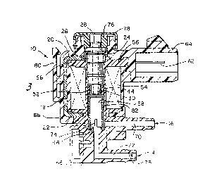
20 Turning now to the drawings, Figures 1 and 2
show an electromechan3.ca~:~valve apparatus generally at
10. The valve apparatus; in the illustrated preferred
embodiment, has a top port 12 for the inlet of fluid at
atmospheric pressure to the valve, and port 14 for the
application of fluid from.or to a vacuum (below
atmospheric pressure) source. Outlet port 15 provides
~ means for adcessing the differential pressure inside
the valve apparatus. The means for accessing pressure
can be utili~~d to operate a vacuum motor or a
di~ph~agm ~perated assembly or any other type of
pressure responsive device.
The electromechanical valve apparatus, as
shown in more detail in Figure 3, includes a plurality
of adjacent magnetic segments which act to define a
magnetic flux circuit with a flux path. The segments
include an iron outer member or mounting bracket 18,
having twe end section which are preferably a top
88084A
4t: j ~J Li
wl3~
section 20 and a bottom section 22. Also in the flux
circuit is a generally cylindrically center member 24.
The center member has a hollow passageway to define a
fluid passage 26 with an inlet port 28 and an output
port 30. The center member is of iron or other
ferromagnetic material.
The center member is shown in more detail in
Figure 4. The center member is formed of a plurality -
of cylindrical portions or sections 31, 32, 33, 34, 35,
14 36. The inner portions 32, 33, 34, 35 are preferably
connected in a stepped or tapered relationship. The
first end portian or top portion 37. of the center
member is also cylindrical-and includes a slot 38
running across Sts midsection. The slot 38 extends
from the upper surface 4~ of th~ top portion 31 to the
upper surface 42 of inner section 32e This slot serves
to allow greater flow of fluid 3nto~the center member
of the valve.
The second end portion or bottom portion 36
of the center member is also-of cylindrical
construction and is preferably of a diameter sufficient
to allo~r sliding along a vertical axis within the
inside of a round non-magnetic seat member 44. The
enter member contains ribs 47, 48 and the non-magnetic
seat member contains ribs 49 to allow an interference
fit within the valve assembly. The non--magnetic seat
44 includes a lower face 50 and an upper face 51.. The
seat 44 also includes a passageway or aperture 52
8~1~~~a~r
'I ~ ~ b,~ ij t~
-~~-
through its center. The bottom portion 36 of the
center member slides along a vertical axis within this
passageway 52 of the non-magnetic seat 4~.
An electrical winding 54, shown more clearly
in Figure 6, as mounted about the center member and
non-magnetic seat. The seat is preferably located near
the center of 'the vertical axis of the winding. The
winding 5~ is encased on its upper, lower and inner
diameter surfaces in a bobbin 56 which is generally of
1.0 plastic, or non-magnetic material. The bobbin gorms a
cylindrical chamber 5~ which.is utilized to contain the
center member and non-magnetic seat. The~center member
24 is adjustable or translatable along the vertical
axis of the winding to abut the upper face 51 of the
non-magnetic seat or to move to a position above ~ttae
non-magnetic seat.
The electric winding is connected to a pair
of terminals 60, 62, shown in Figure 7. The terminals
are c~nnected to a suitable power supply which can
supply an electric current to the winding 54. The
power supply can be a direct current source, a square
wavy generator, a variable resistor, a pulse width
modulation circuit, or an automobile on-board computer
functioning as a signal source.
~ The terminals 60, 62 and bobbin 56 are
maintained in operative relationship by housing 64.
The hous~.ng 6~, preferably formed of plastic, provides
structural support for the bobbin and center member
ab~ve the bobbin. The housing has a lateral portion 66
88o84A
:S
~~a;~~ D~.3'D y
;9 . ~,. F ~ ~.~ vj
-15-
which extends around the outer member 18 and forms a
support and covering for the outer member. The housing
also has a base portion ~8 into which two conduits are
formed. A first fluid conduit 70 ends in port 16. The
second fluid conduit 72 ends in port 7.4. The two
conduits 70, 72 intersect in fluid chamber 74.
A restriction or orifice 75 is provided in
the second conduit 72. The restriction 75 is located -
near the port ~.4 and acts to limit the fluid flow
1.0 within the valve assembly. The restriction is of cross
sectional area which is substantially smaller than the
cross sectional area of the fluid passage 26=through
the center member.
Above the center member 24 is a filter 76
which fits around the top portion 31 of the center
member. The filter acts to prevent materials from
improperly..entering the valve apparatus. Above the
filter is a cap 78 which is removable from the housing
64 to allow adjustment of the inside pieces of the
salve. A clip 80 is also formed in the housing 64 to
permit mounting or other retention of the valve
apparatus.
Beneath the non-magnetic seat is the magnetic
closure meanber or armature member 82. As shown in
26 ~°igures 4 and 5, the armature is preferably an
elongated cup member having a flat top or end portion
84 and a wall member 86. The wall member depends from
the end portion 84 to a base portion 88. Notches 90
are provided in the wall member near the base 88 to
88~84A
~~ " ~r~ a
ai ': ~- ,) ~ t~
-16-
foray a plurality of legs 92. In the preferred
embodiment, the armature has four legs. The wall
member defines a hollow inner portion of the armature.
This hollow inner p~rtion provides a fluid chamber or
differential pressure chamber 74, which is shown in
figure 8. Tine differential pressure.chamber is
operatively connected to the first and second fluid
conduits 70, 72, to allow fluid flow. The armature -
rests or seats against armature seat member 96. The
armature seat member 96 is integrally-formed in the
base portion 68 of the housing. The use of an
elongated armature member elim,iriates the need for a
spring member to 3eeep the ax°~nature in an operating
p~sition, as required in prior art solenoid valves.
generally, the seat 44 is of a soft material
such as brass and the armature is of a harder material
such as iron or steel such that the combination of a
sift material touching a harder material produces a
superior seal. The seat ~n~~ also be of a hard material
2~ such as non-magnetic stainless steel or plastic.
~n alternative embodiment of the armature is
shown in Figures 8, 9 and l0. In this embodiment, the
armature member 82a includes a flat disc member 98.
The flat disc member is retained within the base
p~rti~n 88a of the ax~aaature:82a by a plurality of
ind~ntatiorts 7.0~, 1~2 along the base portion of the
armature: The flat disc momber 3.s annular in shape
end is retained within the indentations in a secure,
but non-tight fit.
88084A
..> .~ , i
~e ~,;' '._ .. '.e ~i ~j
°17a
In the alternative embodiment of Figure 9,
the restriction or orifice 75a of the second conduit is
placed immediately below the base portion of the
armature 82a. Iri this location, the orifice 75a serves
as an armature seat member 96a. The seal between the
flat disc member 98 and the orifice 75a is sufficient
to prevent leakage of fluid from the second conduit
member into the fluid chamber 9~ when the:armature is
in the rest position against the armature seat 96a.
1p Another alternative embodiment of the valve
is shown in Figure ~.1. In this embodiment~ the
armature member 82b is shortened in length. The
armature preferably extends at least beyond..the end of
the outer member in order to complete the magnetic flux
circuit. Notches in the base of the armature member
are not necessary in this embodiment.
In this embodiment, the flat disc.member is
eliminated. In its place, the restriction or orifice
75b is extended within the armature 82b. This. places
2tD the armature seat member 96b within the inside of the
armature member 82b. The seal between the end portion
84 of the armature 82b and the orifice 75b is
sufficient to prevent leakage of fluid from the second
conduit member into the fluid chamber when the armature
is in the rest position against the armature seat 96b.
The prevea~tion of leakage provides the zero bias
feature of the present invention. The extension of the
armature seat into the armature need not include the
88084A
~~~~~'s.~"~~tA"
a 1r .-:, <: ~ vJ J
-
orifice. That is, the armature seat can be extended
while the orifice is maintained at a location near the
port 14.
In all three embodiments, the flat top
portion 84 of the armature 82 acts against the opening
in the lower face 50 of the non-magnetic seat. member
44. The armature acts at various positions between and
including a fully closed position, in which the -
armature is seated against the non-magnetic seat 44,
and a fully open position,. in which the armature 82 is
at its lowest possible position in the cylindrical
chamber 58 and resting against the armature-seat 96.
The opening of the ax~naturs by.its movement in the
vertically downward direction allows fluid flow through
the fluid passage 26 arid non-magaaetic seat 44 and
around the outside of th~ wall member 86 of the
armature thxough cylindrical_ahamber 58 and into the
fluid chamber 74. The downward movement of the
armature thus creates a fluid opening defined between
2~ this lcewer face 50 of the non-magnetic seat and the flat
tcp p~rti~n 8~1 of the armatures. Fluid in the fluid
chamber 74 is accessed by the first and second conduits
7~y 72a
The cross sectional diameter of the fluid
passage 26 is preferably on the order of n.l~~D inch. '
The crops sectional inner diameter of the non-magnetic
seal member is preferably on the order ~f 0.20~ inch.
8808~A
A ~ ~'~ ~~ i i.
'u :~; cf> >,a :r,Zi'
r19~
These diameters are substantially larger than the cross
sectional diameter of the orifice 75 which is
preferably an the order of 0.020 inch.
As described above, the nonmagnetic seat
meanber 4~ is preferably located near the center of the
vertical axis of the electric winding 54 which is near
the point of highest flux density of the winding. The
armature is therefore also located near this same point
of high flux density. The wall portion-of the armature
preferably extends down fram this-center paint in arder
to complete the flux circuit. That length is at least
to the point of the bottom 22 of the outer member 18.
The center member 2~ is slidable within the
cylindrical chamber 58. Translation of the center
member in the vertical direction is effective to alter
the distance of an air gap between the underside of the
laottom portion 3~ of the center member and the top flat
portion 84 of the armature. Alteration of this air gap
distance changes the reluctance of the magnetic flux
circuit of the center member, armature and outer member
and is useful to accomplista the calibration of the
a~Sparatus. The center member can be retained in its
final translated position by the ribs 47 and 48 which
xre in interference fit with the inside of the bobbin
5~. Access t~ the center member is possible through
removable cap 78. once the proper location of 'the
center member 3a attaihed, tl~e center member may be
secured in place by any means known in the art such as
v~elding ~r the use of an encapsulate.
8808~~
,: J. ~.~ r ;
~"~ a t.: A? G! fJ P
°~20°
In operation, the magnetic closure member or
armature 82 is rapidly responsive to an induced
magnetic flux from a current passed through the
electrical winding. ,~ magnetic flux is produced by the
winding in the magnetic flux circuit of the center
member, armature, outer member, and the air gap between
the armature and the center member. When a current is
passed through the winding, the armature 82 is drawn
toward seat 4~. When the current is interrupted, the
~.0 armature falls, by gravity and -the: -force. of the fluid
through the center member, toward the armature seat 96.
When a pressure lower than atmosphere (i.e.,
a vacuum) is impased at port 14, the.vacuum condition
is communicated to fluid chamber 7~ through the orifice
~.5 restriction 75 and fluid conduit 72: A differential
pressure is created in tlx~ fluid chamber 74 by the flow
of fluid at atmospheric pressure in through the center
~nembex inlet port 28, the.fluid passage 26 and out
though the center member output port 30. The fluid
20 continues through the passageway 52 in the ~~n-magnetic
spat ~~, the fluid ~pening created between the seat 44
and the armature 82, and along the outside of the wall
member of tyre armature in the cylindrical chamber 58
though the notches 90 of t3ae armature and into the
25 fluid ch~~ber 74. The different pressure in the fluid
dhamber is accessed through fluid conduit 70 and port
A6o
88084A
~ i
F..d 11j :':. t: ~ j..J Sf : j
-21-
The pressure differential in the fluid
chamber 7~ is altered by movement of the armature in
response to varying the energi~ation level of the
current in the electrical winding. This armature
movement changes the amount of communication of fluid
at atmospheric pressure with the fluid chamber.
Energization of the electrical winding attracts the
armature toward the center meanber, overcoming the
forces of grcavity and the fluid flow through the fluid
opening in the seat. The upward movement of the
armature is limited by the non-magnetic sst..
An empirical illustration of the change.af
the pressure differential (vacuum,..in inches. of mercury)
as a function of the current in ani3.liamperes.for the
invention is shown in &'igure 12. This data is only
representative of a sample plot with one embodiment of
the solenoid valve of the present inventioaa and is not
intended to demonstrate any particular-results other
than the generally expected behavior of the valves of
the present inventiAn.
Translation of the center member of the valve
apparatus elong the flux path alters the portion of the
center segment that is in the flux path. Such
translation also varies the air gap distance between
the armature and the center member and therefore alters
the reluctance of the flux circuit.: The center member
is thus ~ransl~ted along the vertical aa~is to find the
appropriate set point for operation of the valve. Once
t~~;s set point is found, the center member s fixed in
~~084A
~~'~~_'~~~~i;~
~22~
that position and the valve is operated along the
current versus pressure differential curve for that set
point.
In operation, the armature moves vertically
within the chamber formed by the-bobbin. The flow of
fluid around the outside of the wall member of the
armature serves as a sleeve for the travel of the
armature. The utilization of the flow restriction or
orifice 75 results in the low flow characteristics of
1A the valve and a limitation of movement of the armature
to provide changes in the differential pressure in the
fluid chamber:
Utilization of the flat disc member-.98 at the
base of the armature against an armature seat 9s
prevents leakage of fluid from the vacuum source into
the chamber when the armatur~a is fn the rest position
against the armature seat arid the current is removed.
This provides the-zero bias characteristics of. the
present valve, that is, the zero output pressure
2Q differential a~ a condition of zero current. This
relationship is shown in the graph of Figure 11.
~Oreover, 1~cation Of °~he orifice 75a at the point of
the ~~tdr~ peat 96 below the flat disc member 98
reduces the h~steresis effects. This is a result of
the smaller fluid conduit at that point.
The location of the seat member 44 at or near
the point of highest flux density within the electrical
winding provides greater control and repea~abilaty of
the pressure differential versus'current
88089A
~vv'~ ~~J'tl
°~3~
characteristics of the present valve. Providing the
air gap between the armature and the center member at
or near this point of highest flux density provides a
more efficient and responsive valve. This also allows
the use of a lower mass armature. However, the wall
portion of the armature must be of appropriate length
so that the armature remains in the flux path for all
operating positions of the armature; that is, the -
armature wall portion must extend at least to the
bottom of the outer member for all operating positions
of the armature.
The valve is manufactured by assembling the
magnetic segments to form a magnetic flint circuit. The
armature is first inserted intc~~the valve from the top
la and allowed to rest against the armature seat on the
base of the housing. The non-magnetic seat 4~4 is then
driven into the center of the chamber defined by the
bobbin. The non-magnetic seat is preferably located as
near as possible to the midpoint of the longitudinal
axis running through the center of the electrical
winding, i.e., the point of highest flux density. Ribs
along the seat provide the interference fit necessary
to fiold the seat in position.
The center member is then driven into the
center of the valve and above the seat. A current is
applied to the winding and a vacuum source is connected
to the vacuum source port 14. The differential
pressure in the fluid chamber is accessed and measured
through port l6. The center member is driven further
88084A
~: ",
;, .
~w~,;...~.:~r,~';~
~2~4-
into the valve center and measurements taken until the
proper set point of output differential pressure for a
given vacuum pressure is reached. P.t that point, the
location of the center member is further secured by
welding or other appropriate means and the remainder of
the valve is assembled with the filter and cap placed
on the tap of the center member.
Shown in Figs 13 is an alternate embodiment -
of an electromechanical valve apparatus generally at
7.0 110. The valve apparatus 110, as shewn ix~ tha.
preferred embodiment, has a top port 3.12, best viewed
in Fig. 7.4, for the inlet.o:f fluid at atmospheric.
pressure to the valve, and port~7..14 for the application
of fluid from or to a vacuum.(below.atmospheric
pressuxe) source. t~utlet port: 116 provides a means for
accessing the differential pressure inside the valve
apparatus 7.10. As noted above,.. the means for accessing
pressure can be utilised to operate a vacuum motor or a
diaphragm operated assembly or any other type of
pressure responsa.ve device.
The electromechanical valve apparatus 7.10, as
shown in more detail in Figures 7.4, 15, and 16, also
includes a plural~.ty of adjacent magnetic segments
which act to define a magnetic flux circuit with a flux
path. The segments include an iron outer member or
mounting bracket 118, having a middle section 7.7.9
~riented substantially parallel to the axis of the
valve apparatus and two end sections which include
preferably a top section 120 and a bottom section 122.
88084A
A1, vJ ij ij
-~25°~
The outer member is further comprised of a translatable
adjustment plate 123. also in the flux circuit is a
generally cylindrical center member 124. The center
member 124 has a hollow passageway to define a fluid
passage 126 with an inlet port 128 and an output port
130. The center member 124 is constructed of iron or
other ferromagnetic material and is provided with a
notch 132 that receives an ~O~' ring 134 of well known _
construction to provide sealing. At the bottom of the
center member 124 is mounted a non-magnetic valve seat
136. .
An electrical winding 154 is mounted about
the center member 124. The non-magnetic valve seat 136
is preferably located near the center of the vertical
axis of the winding 154. The winding 154 is encased on
its upper, lower and inner diameter surfaces in a
bobbin 156, which is generally constructed of plastic
or so~ae other non~magnetic material. The bobbin 156
fcarm~ a cylindrical chamber 158 which is utilised to
constrain the center member 124. The center member
l~~p in contrast to other embodiments, is not the sole
adjustable segment within the magnetic flux circuit;
alt~nough it may translatable along the vertical axis of
the winding 154 to allow modifications of the
permeability of the primary air gap.
The electric winding 154 is connected to a
pair of terminals 160, 162, shown in Figures 13 and 15.
The terminals 160, 162 are connected to a suitable
power supply which can supply an electric current to
880~4~
~c..~ ..~ s ~ ~J
_2~_
the winding 154. As noted above, the power supply can
be direct current source, a sqtaare wave generator, a
variable resistor, a pulse width modulation circuit, or
an automobile onboard computer: functioning as a signal
source.
The terminals 160, 162 and the bobbin 156 are
maintained in operative relationship by housing 164.
The housing 164, preferably forrued.ofvplastic, provides
a structural support for the bobbin 156 and center
member 124 above the bobbin 156. The housing 164 has a
lateral portion 166 which extends around the outer
member ll8 and forms a support and covering.for the
outer member 113. The housing l6W also has a base
portion 16~ into which two condui~t~s are formed. A
first fluid conduit 170 begins.at an orifice.173 and
ends in port 114: The sec~nd fluid conduit 172 ends at
the port 116. The two conduit~~ 170, 172 intersect in a
fluid chamber 174. The orifice 173 has an~ inner
diameter of aDaout 0.020 inch so as to limit the fluid
flow within the valve assembly 110. The restric~tic~n of
the orifice 173 is of a crass sectional area which is
s~bgtantia7.ly smaller than the cross sectional area o.f
the fluid passage 126 through tine center member 124.
Above the center memiber 124 is a filter 176
which fits around the top portion of the center member
124. The filter acts to prevent materials from
impraperly entering the valve apparatus 110. Above the
filter 176 is a cap 17~ which is removable from the
88084A
~ ~,? :y ~ ~ ~ ~~
-27-
housing 164. A clip 180 is also formed in the housing
164 to permit mounting or other retention of the valve
apparatus 110.
Located beneath the non~~nagnetic valve seat
136 is the magnetic closure member or armature member
182> As the armature 182 can be of similar
construction as the armature 82 shown in Figures 4 and
5, or the alternative armature.;embodiments 82a.and 82b
shown in the Figures 8, 9, 10, and .11.
l~.s can be seen in Figures 14 and 15, a flat
top portson 184 of the armature 182 acts against. an
opening in-the non-magnetic valv~.seat 136> The
armature 182 acts at various positions between and
including a fully closed position,. iri which the
armature 182 is seated against the non-magnet$c valve
seat 136, and a fully open position, in which the
armature 182.is at its lowest possible position in the
cylindrical chambsr 158 and rest~.ng against the
armature seat 196. the opening of the armature 182 by
its movement in the vertically downward direction
allows fluid flow through the fluid passage 12s and
non~magnetic valve seat 136 and around the outside of
the wall ~aember 186 of the armature 182 through
cyl r~drical chamber 158 and into the fluid chamber 174. '
~'h~ downward movement of the armature thus creates a
fltaid opening defined between the lower face of the
n~n-magnetic valve feat 136 and the flat top portion
88084.
~28°-
184 of the armature 182> fluid in the fluid chamber
174 is accessed by the first and second conduits 170,
1?2.
The cross sectional dia~aeter of the fluid
passage 126 is preferably on the order. of 0.100 inch.
The cross sectional inner diameter of the non~magnetic
valve seat 136 is preferably on the order of 0.200
inch. These diameters are substantially larger than
the cross sectional diameter of the orifice 173 which
is preferably on the order of 0.020 inch.
As described above, the non-magnetic valve
seat 136 is preferably located near the center of the
vertical axis of the electric winding 154, which is at
ox near the point of the highest flux density of the
winding 154. The armature 182 ie therefore else
located near this same point of high flux density. The
wall portion 186 of the armature 182 preferably extends
down from 'this center point in order to complete the
flux circuit. That length is preferably at least to
the p~int of tae bottom portion 122 of the outer member
118.
The position of the bottom of the center
member 124, the non-magnetic valve seat 136, and upper
position of the armature 182 define a primary air gap
(or the substantial absence of a magnetically permeable
material). Adjustment of this air gap alters, in part,
the rehactance of the magnetic flux circuit of the
denter member 124, the armature 182 and the outer
member 118. The center member 124, once placed in the
88084A
~j ;~; ~~
... : j ;:~ y,; , 7
~29°
determined position, is retained in position by an
interference fit with the inside of the bobbin 156 and
the outside of the canter member 2.24.
An auxiliary gap is provided by the
configuration of the outer member 118. The outer
member 118 forms, in a planes parallel to the axis of
the apparatus 110 and within the magnetic flux circuit,
a generally rectangular segment 119, best viewed in
f'igura 17. Near the center of the segment 119,
ferromagnetic material is removed froaa the segment 119,
forming a bar 1.21. The bar 121 provides structural
support for the outer membar.118 and maintains the top
portion 120 and the bottom portion 122 in a fia~ad
relation. The translatable adjustment plate 123,
located adjacent the outer member 118, is provided with
a rack of drive teeth 129 on at least one edge and is
held in position within a cavity.131 molded in the
housing 1~4 by retainers 133, as best seen in figure
16. The translatable adjustment plate 123 is initially
pressed into the cavity 132 until it is positioned
~djacel°at ~ht~ segment 119 of tale outer member 118. A
generally cylindrical adjustment cavity 137 is located
to the side of the cavity 131 and receives a non
magnetic adjustment drive gear 202. Although the
~translatabla adjus~tmant plats 123 is generally
immobile, it can be translated in a path parallel to
the saris of the valve apparatus 110 by an external
force, such as torque applied through the non-magnetic
adjustment drisr~: gear 202 engaging the rack of drive
88084A
h-~ r;~ ,~' ; ~ :;~ r~ ; ,
~' :J ~:~:. C.~ Y3 ~ VJ)
-30-
teeth 129 on the translatable adjustment plate 1.23, by
shearing the softer material of the housing 164 in its
path. The resulting adjustable air gap between the
main portion of the segment 11'9 and the translatable
adjustment plate 123 thus form the auxiliary air gap
establishing, in remaining part, 'the reluctance of the
magnetic flux circuit of the center member 124, the
armature 182 and the outer member 118. -
In operation, the magnetic closure member or
armature 182 is rapidly responsive to an induced
magnetic flux from a current passed through the
electrical winding 154. ~ magnetic flux is produced by
the winding 154 via the magnetic flux circuit defined
by the center member 124, the armature 182 the outer
member 118, and the air gap between the armature 182
and the center member 124. When a current is passed
through the winding 154, the ariaature 182 i.s drawn
toward the non-magnetic valve seat 136. When the
current is interrupted, the armature 182 falls, by
gravity and the force of the fluid through the center
member 124, toward the armature seat 96. Optionally, a
re~$lient member such as a spring can be positioned
between the center member 124 and the armature 182 to
bias the armature 182 away from the non-magnetic valve
seat 136.
When a pressure lower than atmosphere (i.e.,
a vacuum) i~ imposed at port 114, the vacuum condition
is communicated to fluid chamber 174 through the fluid
conduit l7a and orifice 17'3. A differential pressure
88084A
~~,~~ Vie,;-
v' ~:~ . G.e s'/
-31~
is created in the fluid chamber 174 by the flaw of
fluid at atmospheric pressure in through the center
member inlet port 128, the fluid passage 126 and out
through the center member output part 9.3~< The fluid
continues through the fluid opening created within the
non-magnetic valve seat 136, along the.outside of the
wall member 186 of the armature 182 in the cylindrical
chamber Z58 and into the fluid chamber 174. The -
different pressure in the fluid chamber is accessed
through fluid conduit 172 and part 9.16.
The pressure differential in the fluid
chamber 174 is altered by movement of the arnaa~ture 182
in response to varying the energizatian level of the
current in the electrical winding.154. This armature
9.82 movement changes the amount of communication of
fluid at atmospheric pressure with the fluid chamber
174. Energization of the electrical winding 154
attracts the armature 182 toward tha center member 124,
avercoaning the forces of gravity and the fluid flow
2~ through the fluid opening in the non-magnetic valve
seat 9.36. The upward movement of the armature 182 is
thus liamited by the non-magnetic valve seat 9.36.
After the enter me~aber 124 of the valve
apparatus is fixed following installation, the
translation of the translatable adjustment member 123
along the flux path alters the outer segment 9.18 to
~lt~r the permeability of the flux path. As
translation of the translatable adjustment member 123
also varies the au~ciliary air gap distance between the
88o84A
a c: ~ s7
.'~ ~ i.~ t~ r.u i~
°-32-
outer member segment 119 and the plate 123, the
reluctance of the flux circuit can be altered. The
plate 123 is thus translated along the vertical axis to
find the appropriate set point for operation of the
valve apparatus 110. ~nCe this set point is found, the
plate is fixed in that position by any means known in
the art, such as welding or the use of an encapsulate.
A dust cover 141 is then placed over the plate 123 and
the cavities 131 and 137 to protect the calibration and
ZO is pressed into a circular collar 143. Thus, the valve
apparatus 110 may be continuously operated along the
current versus pressure differential curve for that set
point.
The location of the non-magnetic valve seat
136 at or near the point of highest flux density within
the electrical winding 154 provides greater control and
repeatability of the pressure differential versus
current characteristics of the present valve.
Providing the primary air gap between the armature 182
and the center member 124 at or near this point of
hiclh~st f~.uac density provides a more efficient and
~:e~p~ns~ve valve apparatus 110. This also allows the
use of ~ lower mass arzaatuxe 182, permitting the use of
the valve apparatus 110 with high frequency input
currents : However, the wall portion of the armature
182 must be cf appropriate length so that the armature
182 remains in the flux path for ail operating
positions of the armature 1821 that is, the armature
88084F~
~~yr~;~~
-33-
wall portion 186 must extend at least to the bottom
portion 122 of the outer member 118 for all operating
position of the armature 182.
This alternative embodiment of the valve
apparatus 110 is manufactured by assembling the
magnetic segments to form a magnetic flux circuit.
First, the non-magnetic bobbin 156 is molded with the
appropriate cavities, conduits and orifices. The -
electrodes 160, 162 are molded into the bobbin 156 at
this time. The winding 154 is then spun about the
bobbin 156 until the preferred~number of the turns are
obtained, where the loose ends of the winding 154 are
then soldered t~ the electrodes~160, 162.' The armature
is then inserted into the bobbin 156 fxom the top and
allowed to rest against the armature seat 2.98 on the
base of the bobbin 156.
The outer member 118, without the plate 123,
is then positioned about the bobbin 156. The flat top
portion 120 is provided with an aperture 125 and slides
2ti over the upper surface of the bobbin 156 and the bottom
portion 122 is provided with a yolk 127 that surrounds
era appropriate molded notch in the base of the bobbin
156. The center member 124 is then driven into the
b9bbia~ l5fi though the aperture 125 into the center of
the valve apparatus 110 and above the armature 182.
The housing 164 is then molded about the assembly to
f~r~t the remaining aspects of the valve apparatus 110.
~~0~~~A
~ci;; e~3~~s ~,
G~ ~,'
_~~-
The translatable adjustanent plate 123 is then
pressed in the cavity 131, as seen in Figure 1~. An
electromechanical valve apparatus calibration mechanism
222, including a calibration fixture 220 and the valve
apparatus 110 is then employed to finally position the
translatable adjustment plate 123. The non-magnetic
drive gear 202, attached to a non-magnetic drive shaft
204 of a fixture stepper motor 206, is either manually
or automatically inserted into the generally
cylindrical cavity 137. The non-magnetic drive gear
202 thus is caused to engage the ~°ack of drive teeth
129 on one edge of. the translatable adjustment plate
123. A control current is applied to the winding under
the control of a microprocessar 20~ and a fixed vacuum
source is connected to the vacuum source port 114. The
differential pressure in the fluid chamber 274 is
accessed and measured by a sensor 210 through the port
1.16. The plate 123 is then translated via rotation of
the non-magnetic drive gear 202 to m~dify the auxiliary
air gags based on measurements taken of the differential
pre$sure via the sensor 210 until the proper set point
of the output differential pressure for the fixed
va~uu~a pressure is obtained. At that point, the
l~sca~~~.on of the plate 123 is secured by welding or
25other appropriate means and the re~aainder of the valve
apparatus 110 is assembled.
'W'hil~ several embodiments of the invention
~~.e illustrated, it will be understood that the
invention is not limited to these embodiments. Those
~8084~.
r: ,~ ~
<~ ° x .. ~'~
1: C.~. . ~, s.~, f
skilled in the art to which the invention pertains may
make modifications and other embodiments employing the
principles of this invention, particularly upon
considering the foregoing teachings. _
What is claimed is: