Note: Descriptions are shown in the official language in which they were submitted.
PATENT
SPLIT P~ECHANICATe FACE SEAL
HACKGROtJND of THE TN~IENTION
Field of the Invention
This invention relates to mechanical seals for sealing
between relatively rotating elements and more particularly to
split mechanical face seals.
Background Art
Mechanical face seals are used with a wide range of
equipment, for example, turbines or pumps, that have a housing
and a shaft which rotates relative to the housing. 8imilarlyl a
large number of pumps, compressors., mixers and agitators~in--
chemical process industries; refineries and~pet~ochemical
industries, as well as a number of other industries, utilize
packed stuffing boxes around their rotating shafts. It has been
found generally desirable to replace the packing in stuffing
boxes with mechanical face seals for reducing high maintenance
costs, preventing environmental contamination, reducing praduct
loss and for other reasons.
Failure or operational deterioration o~ mechanical
seals also is a problem. Repair or replacement of parts of such
seals may be difficult due to the inaccessible location in the
equipment of the component:.parts . :. Cften,_ :because. of-. the design. _.:.
~~~ a~~~
of the equipment, it is difficult or impossible to remove a
damaged seal component beyond the shaft end or to install a
replacement component. Repair of the equipment in those cases
requires entire disassembly, replacement and reassembly of the
housing and component parts of the seal and the equipment.
Replacement of Backing or repair of damaged seals has
been facilitated by seal designs where a portion or all of the
component parts of the mechanical seals are segmented or split.
Installation of split or partially split seal components can be
performed without necessitating the complete breakdown of the
equipment and without having to pass the annular seal over an end
of the shaft. Examples of split or partially split seals can be
found in U.S. Patent Nos. 3,025,070, 3,184,244, 4,423,878,
' 4,575,098, 4,576,383 and 4,576,384. Although the devices taught
by these patents may have been appropriate for the purpases for
which they were intended-,- each of thewdesignswdisclosed thereinw-- ----~ w w
is either overly complicated by an overabundance of component
parts or disposed toward designs which have short periods between
seal failures.
SUMMARY OF THE INVENTION
It is therefore an object of this invention to provide
a split mechanical face seal that is easily removed and replaced
without necessitating removal of a housing and breakdown of the
other components of the equipment.
It is another object of the present invention to
2
CA 02043236 2001-02-22
provide a split seal as:~embly capable of replacing packing
either in stuffing boxe~~ or in defective mechanical face
seals quickly, easily arid efficiently, and without
necessitating the full breakdown of the equipment.
According to ones aspect of the present invention
there is provided a split mechanical face seal for providing
fluid-tight sealing between a housing and a shaft adapted to
rotate relative thereto, said split seal comprising: a)
adjacent, rigid, annular- primary and mating rings each
defining generally radial opposed sealing faces, each of said
rings having a plurality of arcuate ring segments and means
for joining and retaining the segments of each said rings in
rigid connection with the other segments of each of said
ring, whereby each said opposing sealing face defined by said
rings has a smooth surface devoice of discontinuities around
the complete circumference of each said annular ring; b) a
plurality of resilient :split means for positioning and
supporting each of said rings in a generally coaxial
relationship with the shaft and with the other said ring,
said positioning means defining the relative positions of
said rings so that the :pealing face of each said ring is in
opposite and facing relationship to the sealing face of the
other said ring, one of said positioning means rigidly
supporting said primary ring and the other of said
positioning means non-rigidly supporting and biasing said
mating ring in an axial direction against said primary ring,
and further comprising a plurality of split holder means for
circumferentially suppoz-ting each said means for positioning
in a substantially concentric relationship to the respective
ring.
According to a further aspect of the present
invention there is provided a split mechanical face seal. for
providing fluid-tight sealing between a housing and a shaft
3
CA 02043236 2001-02-22
adapted to rotate relative thereto following installation on
a shaft, said mechanica7_ seal comprising: a) a plurality of
arcuate first ring sections which complement each other to
form an annular primary ring defining a generally radial
first sealing face;
b) a plurality of arcuat:e second ring sections which
complement each other to form an annular mating ring defining
a generally radial second sealing face, said second sealing
face, when assembled, opposing said first sealing face in a
sealing relation; c) a first sealing means for sealing a
fluid flow path between said primary ring and the shaft; d) a
second sealing means for' sealing a fluid flow path between
said mating ring and the housing, said second sealing means
being adapted to provide an axial biasing force to said
mating ring whereby said second sealing means biases said
mating ring in an axial direction relative to the housing and
thereby maintains contact between said first sealing face and
said second sealing face, and further comprising a plurality
of split holder means at. least one each for circumferentially
supporting each said sealing means and each said ring in a
substantially concentric' relationship to the respective ring.
According to another aspect of the present invention
there is provided a split mechanical face seal for providing
fluid-tight sealing between a housing and a shaft adapted to
rotate relative thereto, said split seal comprising: a)
adjacent, rigid, annular primary and mating rings each
defining generally radial opposed sealing faces, each of said
rings having a plurality of arcuate ring segments and means
for joining and retain.in.g the segments of each of said rings
in rigid connection with. the other segments of each said
ring, whereby each said opposed sealing face defined by said
rings has a smooth surface devoid of discontinuities around
the complete circumfera_n.ce of each said annular ring; b) a
3a
CA 02043236 2001-02-22
first and second split resilient positioning means for
supporting each respective said ring in a generally coaxial
relationship with the shaft or the housing, respectively, and
with the other said rind, said first positioning means
simultaneously inhibiting translation of said primary ring in
radial, axial and circumferential directions, said second
positioning means inhibiting translation of said mating ring
in radial and circumferential directions, and said
positioning means defining the relative positions of said
rings so that the sealing face of each said ring is in
opposite and facing relationship to the sealing face of the
other said ring; c) retaining elements having rigid walls
that retain each respective resilient positioning means in
concentric relationship to the respective primary and mating
rings, said retaining e7_ements comprising a pair of
semicircular holder members releasably attached to each other
and when in an attached condition, sealingly and compressing
to a limited degree at least a portion of said respective
resilient positioning means.
3b
~~~~~~s
BRIEF DESCRIPTION OF TFiE DRAT~1INGS
Fig. 1 illustrates schematically and partially in
section a conventional pump sealed with packing;
Fig. 2 illustrates in cross section a conventional
mechanical face seal arrangement for use with a stuffing box
housing from which the packing lass been removed;
Fig. 3 illustrates a known split seal arrangement for
use with a stuffing box housing from which the packing has been
removed;
Fig. 4A illustrates in cross section a split seal
according to the present invention for use with a stuffing box
housing from which the packing has been removed;
Fig. 4B illustrates an elevational side view of the
split gland plate utilized in the present invention;
Fig. 4C illustrates a detailed cross section of the
mating sealing element utilized in the present invention;.
Fig. SA illustrates in detail a joint between two ends
of an annular sealing element of Fig. ~A;
Fig. 5B illustrates a back view of an annular sealing
ring ready for splitting for use with the present invention;
Fig: 5C illustrates a cutaway detailed view of the
joint of two halves of a holder for use with the present
invention;
Fig. 5D illustrates in cross section a detailed view of
a compression gear fox use with the present invention;
Figs, 6 and 7 schematically illustrate the compensating
/.
characteristics of the present invention during periods of
misalignment between the shaft and the stuffing box housing;
Fig. 8 illustrates an alternate embodiment of the
present invention utilizing a thrust bearing; and
Fig. 9 illustrates an alternate embodiment of the
present invention having a balanced seal configuration in the
split seal.
DETAINED DESCRIPTIt7N OF THE PREFERRED EMEODI1~IED1T
An example of conventional packing in a stuffing box is
shown in Fig. l,.which illustrates a pump 10 comprising a housing
12, impeller 14 driven by a drive shaft 16, a fluid input chamber
18 and a fluid output chamber 20. Fluid is normally pumped by
the impeller 14 through the chambers 18 and ZO in the direction
of the arrows.
Packing 22 is intended to..prevent leakage of the
pumped fluid to the exterior along drive shaft l6. Packing 22 is
conventionally jam packed within stuffing box housing 24 into
sealing contact with drive shaft 16 by packing fallower 26. The
pressure exerted by packing follower 26 against packing 22 is
increased or decreased by tightening or loosening gland nuts 28,
two of which are shown.
Fig. 2 illustrates the prior art method of replacing
packing 22 with a rotary mechanical seal 30 having a seal rfng 32
with a sealing face 34, usually lapped to a high degree of
flatness. For an assembly not having a split seal, such as that
2~~~~~u
described in U.S. Patent No. 3,961,799, installation is preceded
by removal of the means providing a driving force to the shaft
16, such as a motor (not shown), and then removal of the follower
26 and withdrawal of the packing 22. After removal of packing
follower 26 and packing 22, rotary mechanical seal 30 is
installed.
A special gland plate 36 having a mating ring 38 and
O-rings 40 is fastened to stuffing box housing 24 by means of
gland nuts 28. Gland plate 36 must be fabricated to fit each
size stuffing box. Since each size of drive shaft Z6 normally
has three sizes of stuffing boxes fox various sealed, shafted
equipment, this means that a special gland plate must be made for
each size stuffing box housing.
Fig. 3 illustrates a cross-sectional view of a split
seal design of a seal for replacing packing in a stuffing box, as
is shown and described in U.S. Patent ado. 4,576,364. A spedial w
gland plate assembly comprises a first-gland plate half 36A that
is attached to a second gland plate half (not shown) by socket
head cap screws 38. The gland plate assembly is connected to the
stuffing box housing by gland nuts 28. A split elastomeric face
gasket 41 seals the gland assembly to the stuffing box housing
24. The gland plate assembly houses a rotary split seal ring
assembly 42 and a stationary split seal ring assembly 44.
Rotating split seal rang assembly 42 is held in place
around shaft 16 lax holder halves of which one half 46 is shown
with attachment means, for example, socket head cap screws 48.
6
Tightening cap screws 48 clamps the holders 46 over 0-ring 50
thus sealing the holder 46 to the shaft 16. Rotating ring 52,
also split, is sealed to holder 46 by a split elastomeric boot
54.
Stationary split seal ring 56 is sealed to the gland
plate assembly 36A by an 0-ring 58. Plural springs disposed in
appropriate bores in gland plate assembly 36A, of which one
spring 60 is shown, provide an axial bias against the stationary
ring 56 to bring together the sealing faces 52S and 56S of the
respective rings 52 and 56. The seal as described in U.S. Patent
No. 4,576,384 requires an undue amount of effort and expertise
fox installation. Installation of the seal requires fluid
sealing of joints in split elastomeric elements (40,5,54,58) in
at least four positions.
Moreover, all of 'the separate elastomeric elements. are
installed simultaneously with at least four other rigid elements,
each of which is split. The number of elements that must be kept
in place during the installation process while sianultaneously
screwing together split parts is burdensome. Occasions to
misjain and misalign the split elements either in relation to
their split corresponding parts or in relation to the other
elements of the respective assemblies 42 or 44 are prevalent.
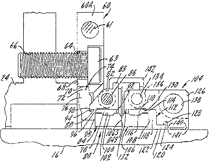
Fig. 4A is a cross--sectional view of tie split seal
according to the present invent~.on. Stuffing box housing 24 and
shaft 16 are in the relative positions as those shown in the
prior art devices of Figs. ~.-3. Fig. 4B illustrates in an
r~ ~~~c~i~~~
elevational side view a gland plate assembly 60 having two split
halves 60A and 60B. The split halves 60A and 60B forming the
gland assembly plate 60 are identical to each other and are
split along a vertical plane as shown in Fig. 4B. One half 60A
is rotated 180° relative to the other half 60B when the two
halves are joined to each other to form gland plate assembly 60.
Referring now to both Figs. 4A and 4B, the gland plate
assembly 60 includes an attachment means, such as socket head
cap screws 61, which screw into a threaded hole 62 in the
respective complementary half gland plate to form the gland plate
assembly 60 that completely surrounds the shaft.
The gland plate assembly is attached to the housing 24
directly, as in the prior art, by bolts 63, one of which is shown
in Fig. 4A having been inserted through a hole 64 in gland plate
assembly 60. A bolt head abuts a shoulder in hole 64 as the
bolt 63 screws into a threaded hole 66 in housing 24. The
precise technique for mounting the gland plate 60 onto stuffing
box housing 24 is not a critical part of the invention, and other
methods, such as those shown in the prior art can be~utilized.
One size of the gland plate assembly 60 can be made to fit a
majority of stuffing box housings, the only requirement being a
clean lateral surface 68 on the stuffing box housing 24.
Threaded bores 172 shown in Fig. 4B are evenly disposed around
the circumference of gland plate assembly 60 and will be used in
the installation of the seal as is discussed below with reference
to Fig. SD.
8
~~~3~~~
Referring now to Figs. 4A and 4C, a gland plate
assembly 60 includes a recessed inner diameter 70 which engages a
lip 72, itself integrally attached at an outer diameter of a
split elastomeric sealing element 74. Sealing element 74 is
alternatively referred to as a compression ring 74 because one
function is to compress the elements of the seal together. The
axial dimension A of lip 72 should be just slightly larger than
the width of recess 70 but the lip 72 should easily fit within
the inner diameter of the gland plate assembly 60. The gland
plate assembly 60 will squeeze the lip 72 against the lateral
surface 68 of stuffing box housing 24 when assembled. A clean
lateral surface 68 will thus ensure a close, tight fit and a good
seal between the gland plate assembly 60 and the stuffing box
housing 24.
Sealing element or compression ring 74 includes a
middle section 76 which biases an essentially tubular extension -
?8 at the opposite end of sealing element 74 from lip 72.
Tubular extension 78 engages a stationary split seal ring
assembly, which in this embodiment is a mating ring assembly,
and is generally designated by the numeral 80 in Fig. 4A. The
sealing element 74 is constructed in a way that when fully
assembled, it seals against leakage of fluid under moderate
pressure from one side of the seal to the other. The sealing
properties will be discussed below. Fig. 4C shows a cross
section view of sealing element 74 in a non-stressed position,
whereas the view of Fig. 4A shows the sealing element 74 in a
9 .
stressed position.
The resiliency of the middle section 76 of elastomeric
element 74 together with the structure of component parts of the
ring assembly 80 create an axial biasing force which pushes the
interconnected ring assembly 80 away from the stuffing box
housing 24. Moreover, this biasing force is adjustable since the
amount of force provided in the axial direction depends on the
axial position of ring assembly 80. For example, a greater axial
biasing force will be provided if the sealing element 74 is
compressed to a greater degree by shifting the ring assembly 80
toward the stuffing box housing 24.
Stationary primary ring assembly 80 comprises a split
holder 82, including the component parts, 82A and 828, and a
split mating sealing ring 84, having a sealing face 84S. Holder
82 comprises two halves 82A, 82B, each of which includes a
through hole 86 for insertion. of._a. bolt.162.,--.further .described ....
with reference to Fig. 5C below. Each of the two bolts will
engage a corresponding screw-threaded hole on the complementary
half of holder 82 arid tightening of the bolts will form a unitary
annular assembly for holding and postioning the stationary
mating sealing ring 84. An annular flange 83 extends from the
circumferential outer edge of holder 82.
Holder 82 comprises a hard material, such as metal,
and at its inner diameter portion 88 provides support to the
outside surface of tubular extension 78. An inner diameter
portion 88 is defined by a flange member 90 at one end and a
~ 2p~~~~~
second flange member 92 at the other end. Flange member 90 fits
into a corresponding groove 94 in the tubular extension 78.
Inner diameter portion 88 further includes a recess 96
which can collect any excess elastomeric material which results
from compression ef tubular extension 78. Similarly, tubular
extension 78 does not extend to the total axial width of inner
diameter portion 88, i.e. up to flange member 92, and thus
provides a volume into which excess compressed elastomeric
material from tubular extension 78 can extend when holder 82 is
screwed together.
The inside surface of tubular extension 78 engages
mating sealing ring 84. Sealing ring 84 comprises a paix of
split halves that axe joined together and surrounded on the outer
circumference by tubular extension 78. A flanged portion 98 of
tubular extension 78 provides axial support to sealing ring 84
and biases the ring 84 away from the stuffing box housing 24. An.
abutment 100 on the inside surface of extension 78 fits snugly
into a reciprocal shallow groove detent 102 in the circumference
of sealing ring 84.
Sealing member 74 provides axial, radial.and
circumferential support to sealing ring 84, and also seals the
passage between ring 84 and holder 82. The sealing member 74
also seals the housing 24 against the gland plate assembly 60 by
compressing lip 72 against surface 68. The sealing member 74
also provides an axial biasing force to the ring assembly 80.
The dimensions of sealing member 74 are dependent on.
11
~~~~c~~t~~
the diameter of shaft 16 and on the remaining elements with which
sealing element 74 engages, such as primary ring 84 and gland
plate assembly 60. Certain dimensions, such as the axial width
AE of tubular extension 78 and the height HA and width WA of the
abutment 100, can be set at standard values which match the
standardized dimension of the ring groove and the holder for
different size seals. The height HT of the transition portion 76
may also be set to a standard height as long as HT is large
enough to enable sealing Zip 72 to engage the surface 68 for a
majority of sizes of stuffing box housings 24.
Referring again to Fig. 4A, rotating split seal ring
assembly, generally designated 104, in this embodiment is a
primary ring assembly. It includes a split primary sealing ring
106, having a sealing face 106S which is in direct, opposing
relationship to face 84S of the mating ring 84. A surface 108
extends radially at an opposite side of ring 106 in a plane
generally parallel to sealing face 1065. The split halves of the
sealing ring 106, when joined, form an annular member with a
detent 110, similar to detent 102 on ring 84, for receiving an
abutment member which together facilitates the axial and radial
positioning of ring 106.
Ring assembly 104 also comprises a rotating elastomeric
sealing element 112 that has a tubular extension portion 114 that
fits around and provides support to the primary sealing ring 106.
An abutment 116 disposed on the inside surface of a tubular
extension portion 114 has a shape that is reciprocal to and fits
12
snugly within detent 110 in the outer diameter surface of ring
106. Transition portion 118 of sealing element 104 provides
axial support to the radially extending surface 108. The
elastomeric properties of tubular extension portion 114 and
transition portion 118 effectively seal ring 106 to prevent fluid
from passing between ring 106 and sealing element 112.
Sealing element 112 further comprises a shaft sealing
portion 120 having an inside surface 122 which effectively seals
the fluid path between element 112 and shaft 16. A flanged lig
124 at the end of shaft sealing portion 120 cooperates with a
rotating holder 126 to seal the shaft sealing portion 120 against
the holder 126. Insertion of the lip 124 into a grooved detent
128 in the inside surface of holder 126 and compression of the
shaft sealing portion provides good sealing capacity.
The inside surface of holder 126 generally follows the
outline of the outside surface of sealing element 112 so as to
create amore effective seal between the holder 126 and sealing
element 112 and to rigidly support ring 106. Tiolder 126 also
provides a shallow groove 130 and a space between flange 132 and
tubular extension portion 114 for receiving~excess elastomeric
material from element 112 when it is compressed in the assembled
position. The sealing element i12 is split as are all the
elements of the rotating ring assembly 104. The axial and
radial dimensions of'sealing ring 106 and of sealing element 112
may also be matched to standard values so that the sealing
element may be usable with different size shafts:
13
2~~~~~~~
The .rotating holder 126 is split in two halves, one
half of which is shown in Fig. 4A. Each half comprises a through
hole 134 with a flanged abutment 136 (shown in phantom). A bolt
(not shown) is passed through hole 134 and its head engages the
flanged abutment 136. The bolt is screwed onto a threaded bore
(not shown) in the complementary half of the holder 126 to unite
the holder. As the bolt is screwed into the complementary half
of holder 126, the assembled unitary holder provides sealing
pressure on the sealing element 112.
A second through hole 138 may be provided to thoroughly
secure the holder 126 about the shaft 16. The holder 126 has a
pair of flanged, annular supports 140 having an inner diameter
surface 141 which directly contact shaft 16. The supports 140
are the base which maintains the holder 126 in a predetermined
secured position in the axial direction along shaft 1.6.
Tightening of the bolts (not shown) which tit through holes 13.4..: __.
and 138 provides a positive drive capability that results in
friction engagement of the shaft 16 with the support surface 141
and with surface 122 of element 112. The positive drive
capability avoids axial and circumferential translation of 'the
rotating mating split seal ring assembly 104 with respect to the
shaft 16. The holder 126, as is holder 82, also disposes two
identical halves at 180° relative to each other for attachment,
much as is the gland plate assembly 60 shaven in Fig. 4B.
The predetermined axial. position of the ring assembly
104 also illustrates another very important aspect of the present
I4
~~~~~~3~
invention. The ability to slide the ring assembly 104 along the
shaft 16 to a predetermined position permits the assembler of the
split seal device to pre-stress the amount of axial spring force
which the sealing element 74 provides in biasing the sealing
face 84S against sealing face 106S. The amount of spring force
provided by element 74 is dependent on the axial position of
stationary mating ring assembly 80 which in turn depends on the
axial position of the rotating primary ring assembly 104. The
operator can slide the rotating ring assembly 104 to the
predetermined position along shaft 16 to provide exactly the
axial spring force which is desired from the sealing element 74.
The pre-stressing capability of this invention is an important
characteristic for effective sealing of devices.
An optional elastomeric cover guard 142 is disposed
over flange 83 of the stationary holder 82. A decent in the
inner surface of guard 142 fits snugly over the flange 83. The
guard protects the seal and the sealing faces 84S and 1065 from
debris. The guard also deflects any of the sealed fluid which is
slinging out of the seal faces as the shaft 16 and sell ring 106
rotate at high speed.
Assembly of the seal is performed easily and
efficiently. Using the replacement of packing by a mechanical
seal as an example, the packing is first removed fram the
stuffing box housing 24. An elastomeric sealing element 74
having predetermined dimensions, as shown in Figs. 4A and 4C in
cross section, is provided for circumferentially press--fitting
within the gland plate recess 70. Manufacture of the sealing
element 74 and of the sealing ring 84 precedes their assembly
into a seal.
The sealing element 74 may be manufactured by forming
an entire sealing element ring having the desired dimensions and
then cutting through the ring with a knife. Cutting or splitting
the ring will permit slipping the sealing element 74 around shaft
16. The preferred technique of cutting the sealing element 74 is
straight radial cut. Atlernatively, the cut may be made at an
angle to the perpendicular, thus allowing some play in fitting
the cut ends together during assembly. An angled cut also
provides better sealing characteristics when the two cut ends are
pressed together during assembly. As will be d:Lscussed below,
the sealing properties of sealing element 74 are further enhanced
by the inventive design, which relies on the hoop stress
inherently present in the middle.section 76 of the sealing
element 74 to provide a sealing capacity for fluids even if the
fluids axe under moderate pressure.
An alternative technique is to have a Long, wound coil
of extruded elastomeric material having a cross sect3.on as shown
in Figs. 4A and 4C. The required predetermined length which will
fit around recess 70 of the coil is cut, preferably at an angle.
Different lengths can be cut to fit different sizes of shafts
used in pumps or turbines. Using sealing element 112 as an
example, the cut can be made by a special cutting jig so that two
interlocking round ends 150 and 152 of the coil length, shown in
16
~~~~t~~~
Fig. 5A, can be spliced together to form an effectively
continuous annular sealing element. Alternatively, a dovetail
shape (not shown) may be cut and spliced to form the sealing
element 74.
The two halves 60A and 60B of the gland plate assembly
60 are then brought together, making sure that the lip 72 of
sealing element 74 is within the recess 70 in the inner diameter
of gland plate assembly 60. The gland plate assembly 60 is
screwed together by bolts and is then brought against stuffing
box housing 24 with care to insure that lip ?2 is flush with the
surface 68 around the complete circumference of recess 70. A
thin film of sealant, such as RTV SEALANT made by Dow-Corning
Corp., preferably is coated onto surface 68 of the stuffing box
housing 24 where the lip 72 of compression ring 74 will contact
so as to increase the sealing capabilities. The gland plate
assembly 60 is then attached to the stuffing box housing 24 by .
screwing bolt 63 into threaded bore 66. At this stage, the bolt
63 should not be tightened completely in bore 66. The two halves
of stationary primary ring 80 are then assembled by placing them
into the inner diameter of tubular extension 78 one at a time,
making sure that the sealing face 845, having a beveled outer
edge, faces outward. The other half of the sealing ring 84
should be placed into the tubular extension with care, making
sure that the split in the sealing ring 84'is 90° relative to the
split in the compression ring 74. Disposing the split at a 90°
angle provides better sealing capability.
The two halves of the stationary primary ring 84
match perfectly at the joint ends because of the technique by
which they are manufactured. 23anufacture of sealing ring 106 is
identical and will be herein described by way of example.
Fig. 5B illustrates ring 106 in a front view of the
radially extending surface 108. The ring is first manufactured
as an integral ceramic or carbon sealing ring 106. The sealing
ring 106 is then lapped to a smooth, optically flat finish as is
done with a sealing ring which is not intended for splitting.
Two diametrically opposing notches 154 are then ground into
surface 108 and around the edge of surface 108 and into the inner
diameter of the ring. The notches should be ground to a
sufficient depth to cause slight weakness in the ring but not so
deep that the ring fails to maintain its sealing properties,
Optimally, the depth of notches 154 should be about 10~ of the
thickness of ring 106, or about 10~ of the distance between faces
106S and 108.
A tool with a cutting edge (not shown) is then placed
in the notches and pressure is carefully exerted onvthe face 1065
of ring 108 at points approximately 90 degrees from the notches
154 on the ring, or at about the areas designated 156 on the
ring. Exerting careful but steady pressure on the back side 108
against the ring 106 causes the tool edge to create a stress at
the notches 154. The pressure at points 156 is increased until
the ring snaps into two pieces at the notches. The function of
the two pieces will be fagged, but the technique forms two
18
perfectly matching surfaces that fit together well in a joint
that is apparently continuous across the ring surface 1065. The
characteristics of the jagged surfaces between ring ends also
provides a, much better sealing capability than does a flat end
joint.
Returning once again to assembly of the seal with
reference to Fig. 4A, the ring 84, which has been manufactured
using the above technique, is joined together and fit into
tubular extension ?8. Abutment 100 fits within the shallow
groove 102 of ring 84. Care must be given to ensure the meshing
of the jagged surfaces of the split ring. A smooth, flat surface
84S capable of sealing is provided by the joined ring 84.
Two halves of stationary holder 82, also referred to as
a clamp ring 82, are then brought together from the outside, and
are press fitted around tubular extension 78. The inner diameter
of the two halves of stationary holder 82 are preferably lightly
lubricated with silicone grease, but only at the area immediately
surrounding the split.
Fig. 5C illustrates how the two halves 82A and 82B are
bolted together by a bolt 158 which fits through hole 86 in
holder half 82A and screws into a threaded bore 160 in the
complementary holder half 82B. Socket head 162 of bolt 158 abuts
against the surface 164 of a recess 166 cut out from the
circumference of the end of holder half 82A. Screwing the bolt
158 into the threaded bore 160 brings the head l62 within the
recess 166 to obtain a relatively uniform circumfexential
19
2~~.~~~~
profile. The holder 82 is screwed together loosely by tightening
the screws only a few threads. The split in holder 8Z should be
circumferentially aligned approximately with the split of the
sealing ring 84. The bolt 158 is not visible in a side view of
holder 84.
The diametrically opposed ends of balder halves 82A and
82B are joined in an identical manner except that the recess 166
is cut out of the holder half 82B and the threaded bore 160 is in
holder half 84A; similar to the gland plate halves 60A and 60B
described above with reference to Fig. 4B. The assembly of the
seal according to the invention proceeds much more easily and
with fewer pieces to retain in place during the assembly process
than in assembly of presently known split seals.
Referring again to Fig. 4A, the gap.between shaft 16
and the inner diameter of stationary sealing ring 84 around the
circumference must be carefully checked to ensure a concentric
relationship between the shaft 16 and ring 84. Axial alignment
is also checked both visually and by running a fingernail along
the split to see if there is a step at the joint. Careful
alignment of the halves may be necessary to provide a flat
sealing face 845. The holder halves are then tightened by
screwing bolts 158 until the ends of the holder halves completely
touch, checking the radial axial and circumferential alignment of
the scaling ring 84 frequently. Gland plate assembly 60 is then
tightened down by fully screwing in bolts 63 within bore 66 of
the housing 24. Tightening bolts 158 forms a complete mating
r ~~~~2~~
ring assembly 80 which is ready to be pre-stressed using the
compression gear 167 illustrated in Fig. 5D.
Fig. SD shows in detail a compression gear 167 having
predetermined dimensions for setting the desired axial spring
force of sealing element 74. Compression gear 167 comprises a
hollow, cylindrical tube having a hollow bore 168 and an annular
flange 169 extending from one end of gear 167. The hollow bore
168 has a diameter which is large enough to germit easy passage
of a bolt I70 through it. The bolt 170 is screw-threaded and
screws into a screw-threaded bore 1?2 (see Fig. 4B) in gland
plate assembly 60, which is spaced fxom bores 64. Tightening
nut 174 translates holder 82 toward the housing 24 and
necessarily stresses the transition section 76 of sealing
element 74 causing it to become stressed.
A plurality of compression gears 167 are disposed
around the circumference of gland plate 60. preferably four
compression gears 167, spaced at 90° to each other, Will permit
even compression of the compression ring/sealing element 74
around the circumference of the holder 82. Careful monitoring of
the axial position of the holder 82 relative to housing 24, also
referred to as a "working height," may be necessary to ensure
proper installation.
Evenly tightening the nuts 1?4 further translates the
compression gears 167, the flanges 169 of which engage and
translate flanges 83 on the outer diameter of holder 82, to a
desired axial gosition or "working height". For a shaft size of
~U~3~~~
about 6 inches diameter, it has been found that a working height
of about 2.6 inches is appropriate, with the nut 1?4 having a
hollow bore 168 of sufficient length to provide the appropriate
working height. A pressure of approximately 150-300 pound load
is then pravided on the compression ring/sealing element ?4, with
approximately a 225 pound load being optional for a shaft having
a diameter of 6 inches.
Referring again to Fig. 4A, the next step in the
assembly is the insertion of the rotating mating ring assembly
104 around shaft 16. Rotating primary ring 106 is first split
according to the technique described above with reference to Fig.
5B. For larger shaft diameter installations, the two halves of
rotating ring 106 can be joined at their ends and taped together
around shaft 16 to facilitate assembly. Sealing element 112 is
then wrapped around ring 106 and the two halves of rotating
holder 126 are brought around the shaft and the sealing element
112. The sealing element 112 is preferably cut at an angle to
the perpendicular so the pressure of the assembled holder 126
squeezes the wedges of the cut sealing member 112 and provides a
better seal. Alternatively, a rounded or dovetailed end is cut,
with the two ends interlocking as shown in Fig. SA, to provide an
annular seal having good sealing characteristics.
Bolts (not shown) axe fit through holes I34 and 138 and
loosely screwed into the corresponding screw-threaded holes (not
shown) in the complementary half of rotating holder 126.
Reference to Fig. 5C which describes assembly of the stationary
22
r.
holder provides guidance with respect to the assembly of split
seal elements. The bolts should be screwed in loose enough to
permit the primary ring assembly 104 to slide axially along shaft
I6 with little effort. It is important to verify that sealing
face I06S is perpendicular to the axis of the shaft 16 at this
stage and all throughout the assembly of the seal.
The rotating primary ring assembly 104 is then brought
toward the stationary mating ring assembly 80 until the sealing
faces 84S and 1065 are just barely touching. The mating ring
assembly 80 is retained in a pre-stressed position by the
compression ring 167, as is described with respect to Fig. 5D
above.
The bolts connecting the two halves of holder I26 are
then tightened completely. Tightening of the bolts which fit
into holes 138 provides a clamping force on the annular flanges
140 at the base of holder I26. The friction between shaft
sealing portion 120 and the shaft 16 and between flanges I40 and
the shaft 16 fix the position of the assembly 104 relative to the
shaft 16 in the axial and circumferential directions. Tightening
of the bolt in hole 134 takes the fluid pressure created by the
pump from the inner diameter of ring 84~
The structure of the inner surface of sealing element
I12, and especially of the matching contour of sp~.i~ seal ring
106 and the inner surfaces of tubular extension 1I4 and
transition portion 118, grips the sealing ring 106 and rigidly
supports it in the axial, radial and circumferential directions.
23
20~~~ ~6
Motion of the sealing ring 106 in any direction relative to shaft
16 is thus severely inhibited during operation of the pump. The
sealing element 74 also inhibits the motion of sealing ring 84 in
the radial and circumferential directions but not in the axial
direction. The sealing element 74 provides impetus only for
axial motion of the sealing rings of the seal, i.e., for motion
of the mating ring assembly 80 relative to the housing 24.
Following tightening of the bolts in holes 134 and 138,
the compression gear 167 together with bolt 170 are removed and
the spring force of the sealing element 74 will freely bias
sealing ring 84 toward sealing ring 106. The biasing force has
already been pre-stressed by the torque of bolt 170 acting on
compression gear 167 and thus the precise amount of force
necessary~for creating the sealing capability required by the end
user for the particular device is provided.
A significant feature of the invention with regard to
sealing element 74 will become apparent from the above
description. The sealing element 74 is split along its complete
cross-sectional dimension so that it can be installed around a
shaft. both the lip 72 and the tubular extension 78 are
compressed by the elements.which are being sealed. That
compression creates a seal which is good up to fairly high
pressures. The middle section 76, however, is unsupported by any
hard material elements and fluid under pressure on one side of
the sealing elemement 74 is liable to leak through the split in
the sealing element. A significant feature of this invention ~.s
24
the design of sealing element 74 and holder 82 which provide
sufficient hoop stress in middle section 76 to counteract the
moderate fluid pressures to which the sealing element 74 will be
subjected. The hoop stress provides a tension between the lip
72 and extension 78. Flanged portion 90 of the holder 82
provides an inwardly radial stress to middle section 76 that
tightens the junction of the two split ends to seal fluid under
moderate pressure from leaking through sealing element 74.
The last step in the assembly of the seal is the
fitting of the guard 142 over flange 83. Guard 142 also
comprises a split elastomeric element and has two ends which are
brought together and joined by stapling, gluing or other
appropriate means. The guard provides protection of the seal
..
faces from the ambient environment and also acts as a shield for
fluid which is slung from the rotating face 1065.
The composition of the materials for each separate
component can be customized to achieve the appropriate sealing
capability desired by the end user. The gland plate assembly 60
and each of the holders 82 and 7.26 comprises-a hard material such
as metal, preferably a noncorrosive metal such as st~~.nless
steel. Bolts, nuts and other connectors are also preferably
stainless steel.
Typically, the sealing rings 84 end 106 maybe made
from an appropriate material, such as carbon, ceramic, silicon
carbide or tungsten carbide. Combinations of rang materials for
each of the rings 84 and 106 are also possible. Far example, two
CA 02043236 2001-02-22
silicon carbide rings may be used, or one ring may be made of
carbon and the other of ceramic. Other materials may be
substituted for those set forth above, as is known in the
art.
The sealing elements 74 and 112 comprise a resilient,
somewhat flexible elastomeric material. An ethylene-propylene
(EPDM) compound having t:he brand name CRANELAST*, sold by
John Crane Inc., has been found to work well. Other
elastomeric compounds such as Buna-N or AFLAS*, available
from 3M Corporation, have also worked well in the past as
sealing element material., and other materials are known to
those skilled in the art:. 'The materials used in the
elastomeric elements are chosen with a view toward the fluid
which the equipment is intended to pump so that no adverse
chemical or physical reaction will result between the
elastomeric material and the fluid.
Another important. aspect of the invention during
operation is the flexi:nc~ capability of the sealing elements
of each of the rings. Shaft 16 is normally susceptible to
some play in its axial direction as it rotates, and it may
also experience runout canditions. The shape of split sealing
element 74 permits it to automatically compensate for these
conditions.
Transient or permanent misalignment of the shaft axis
relative to the stuffing box housing 24 is compensated by the
spring force of the mating ring sealing element 74. Moreover,
the shape of the sealing- e:Lement 74 permits it to provide
support to the stationary mating split seal ring 84 in the
radial and circumferential directions. The sealing element
spring force
* Trade-mark
26
2~~~~~~
further provides a bias to the ring 84 in the axial direction
ar~und all of its circumference within certain parameters. Figs.
6 and 7 schematically illustrate a shaft 16 which is in,
respectively, aligned and misaligned positions with reference to
the stuffing box housing 24.
Under aligned conditions, as illustrated in Fig. 6,
there is essentially circular symmetry all around the sealing
ring assemblies 80 and 104. In particular, the mating ring 84
has an identical spacing and angular position relative to the
stuffing box housing 24 around the complete circumference of the
ring assembly.
Fig. 7 illustrates in exaggerated form a misaligned
shaft 16 relative to the housing 24. The misalignment has been
so positioned that the greatest angle of misalignmewt is shown in
the plane.through which the cross section has been taken. The
distortion of sealing element 74 has been exaggerated to better
illustrate the effective operation of the invention.
As shown schematically in Fig. ?, the stationary
mating ring 84 has been angularly displaced from the~position
shown in Fig. 6, to maintain a parallel relationship between
sealing faces 84S and 106S. Axial spring force from the sealing
element 74 on ring 84 maintains a positive static seal condition
of the sealing faces 84S and I06S at all times during rotation of
the shaft 16. The seal is static because the sealing element 74
is compressed to the same degree all around the circumference of
the sealing element 74 through a complete rotation of the shaft
27
16. Qther than for the transient events, the sealing element 74
does not distort during any portion of the rotation of the shaft
16. The shape and position of sealing element 74 remains in
approximately the same position shown in Fig. 7. Transient
conditions may cause the sealing element 74 to temporarily
compress or expand, but on average, little distortion of the
sealing element 74 will take place. Thus operation of the seal
will avoid early failure from deterioration of the sealing
element 74 caused by continual flexing due to shaft rotation.
Fig. 7 further illustrates the importance of a
perpendicular alignment sealing face 106S of ring 106 with
respect to the axis of shaft 16. As shaft 16 rotates, a
perpendicularly aligned sealing face 1065 will rotate in a plane
which does not precess or oscillate. On the other hand,
deviation from a perpendicular relationship will cause an axial
oscillation of the sealing face 1065. The oscillation will be
frequency dependent on the speed of the shaft rotation, which can
exceed 300 revolutions per minute. The response time of the
axial spring force provided by sealing element 74 can compensate
for some precession or oscillation, but at higher frequencies,
the oscillations will tend to maintain a gap between seal faces
845 and 1065 which is larger than desired for effective sealing.
Continued and extended rotation of the shaft and nonperpendi~
cularly aligned sealing face will lead to aging and wearing out
of the resiliency of sealing element 74. It is therefore
important to provide as close to a perpendicular relationship
28
between sealing face 1065 and the axis of shaft 16 as is
possible.
As illustrated in the view of Fig. 7, the resiliency of
the elastomeric material forming sealing element 74 provides a
varying amount of axial spring force on different portions of the
circumference of assembly 80. However, the inertial momentum
provided by the weight of holder 82 knot shown in Fig. 7 for
purposes of clarity) maintains a relatively uniform axial biasing
force on the ring 84 to keep the sealing face 84S in
substantially the same plane as the sealing face 106S of xotating
ring 106.
Although this invention has been described with
reference to conversion of an exemplary pump having a stuffing
bore, other applications will readily come to-mind of a person of
skill in the art. The versatility of a split seal configuration
lends itself to many varied applications. Its use i.s appropriate
wherever a mechanical face seal must be installed ~ithou-t
requiring the breakdown of the equipment on which it is mounted.
Other uses with appropriate modifications are contemplated in
tight fitting quarters where removal of a housing or of a shaft
attachment is difficult or impossible, as well as where access to
the shaft end is difficult.
The advantages of the inventive split seal are apparent
to those of skill in the art, and include the capabila.ty to
quickly, easily and efficiently install or replace packing or a
defective seal. The inventive'seals are suss~ptible to being
a9
used to much greater pressures than heretofore permitted by
packing. The inventive seal also provides for adjustable
garameters, such as the spring force provided by the sealing
element 74.
The sealing requirements for a particular pump or
turbine may change because of a change in the fluid that is being
sealed. Continued use of a split seal made according to the
present invention may cause the sealing element 74 to age and its
spring force to decrease. To adjust for this eventuality, the
rotating ring assembly 1.04 can be axially shifted relative to
stuffing box housing 24 until the desired pressure is achieved.
This procedure provides a greater useful life to the spring and
flexibility to the pump user. When the rotating primary ring
assembly can no longer compensate for wear by shifting for a
deteriorated sealing element 74, all of the component parts of
the split seal can be removed easily and replaced by new parts.
The seal according to the present invention can be
installed in tight places, since it has a very short axial
length. Reduction in weight of sealing materials in excess of
90~ have also been provided by the inventive split.seals over
other retrofitted seals.
Other modifications to the invention are possible and
will become apparent from the requirements of an end user. ~'or
example, certain pumps or turbines have shafts which are
subjected to greater than normal axial shifts during use. The
shifts may exceed a predetermined amount which can be compensated
for by flexing of the sealing element 74 of Figs. 4A and 4C.
As is illustrated in Fig. ~, a thrust bearing 176 may
be welded or clamped around the shaft 16. Tnstead of a gland
plate assembly, an adaptor ring 178 is disposed around the shaft
16 and an annular groove 180 provides a loose fitting collar for
the thrust bearing 176. An adapted gland plate 182 is suitably
attached to the adapter ring I78 and squeezably retains lip 72
against the adapter ring 178. The remaining elements of the seal
ring assemblies 80 and 104 are identical to those described
above.
Thrust bearing 176 acts to maintain an appropriate
axial position of the adapter ring 178 relative to the shaft.
Rotation of the shaft 16 and the thrust bearing 176 does not
affect the adapter ring 178 since there is only a slight
frictional contact between the annular groove 180 of ring adapter
178 which defines the collar and the thrust bearing I76. As the
shaft 16 and thrust bearing 176 axe axially translated, one or
the other of the radial surfaces of the thrust bearing also
translates the collar and ring adapter in the direction which the
shaft is moving. The movement of the ring adapter 178 also
necessarily will translate the stationary mating ring assembly
80. Of course, rotating ring assembly 104 fixedly attached to
shaft I6 will be translated lay axial motion of the shaft.
Ring adapter 178 also is a split element and ~eguires
a bolt to be inserted through the bolt holes 183 and 184 for
joining the two halves together. The structure and procedure is
31
2fl~~2 ~~
similar to the bolts utilized in holes 86, 134 and 138. A
tubular extension portion 186 of ring adapter 178 fits slidably
within the stuffing box housing 24. The housing 24 and ring
adapter 178 encloses an 0-ring 188 within an annular groove 190
at the end of the extension portion 178 which creates a seal in
the fluid path between the housing and the adapter.
Alternative embodiments of the inventive split seal may
be designed for particular needs or requirements of specific
industries and applications, Fig. 9 illustrates a variation of
the split seal illustrated in Fig. 4A, where like elements are
indicated by identical numberals having a prime annotation
The embodiment of Fig. 9 has been particularly designed
for applications having large shaft diameters. It has been found
to work particularly well for seals installed with shaft
diameters of between 7 inches to about 30 inches.
The embodiment shown in Fig. 9 is different from that
of Fig. 4A in several respects. In particular, the Fig. 9
embodiment introduces a sleeve 200 on which rests the inside
surface 122' of the shaft sealing portion of sealing element
112'. The rotating holder 126' has a step 202 which
accommodates the sleeve 200. The annular supports 140' of holder
126' directly contact the shaft 16' at the inside suxfaces 141'.
Other specific da.fferences become apparent from a close
comparison of the twa embodiments of Figs. 9 and 4A. The flanged
portion 98' of sealing element 74' is longer in cross section,
and of wider diameter when viewed along the centerline, sp as to
allow greater distance between the shaft 16' and the stationary
ring 84'. The flange member 90' of stationary holder 82' is
correspondingly longer in the cross-sectional view of Fig. 9.
The flange member 90' provides a closer fit and greater srpport
to ring 84' by biasing the sealing element flanged portion 98'
against the ring 84'. This arrangement of the longer flanged
members 90',98° provides increased hoop stress to both the middle
section 76' and the intermediate part between the middle section
76' and the flanged portion 98'.
Similarly, transition portion 118' is correspondingly
longer in cross section and is also matched by a w~.der axial
diameter of the rotating holder 126', which provides support to
rotating ring 106'.
zt is also important to note the recessed grooves 204
in each of the inner diameters of rings 80' and.106'. Grooves
204 cause the rings 84' and 106' to contact each other only at. a
surface 206 close to the ring outer diameters.
Another difference shown in the embodiment of Fig. 9 is
the wider axial diameter of the gland plate 60', which includes
an annular flange extension 208 at the inner diameter of the
gland plate 60'. Moreover, the recessed inner diameter 70' of
the gland plate 60' is deeper and encompasses the majority of the
sealing lip 72'. The protruding flange extension 208 extends
inwardly from the inner recessed diameter 70' and firmly engages
lip 72° to create a seal against the lateral surface 68 of the
housing wall. This arrangement is designed to withstand higher
33
~~~~J2~~
pressures generated by the device which is being sealed. In most
other respects the seal shown in Fig. 9 is identical to the
embodiment shown in Fig. 4A.
The design of the embodiment of Fig. 9 is balanced and
permits the seal to be used with shafts of greater diameter. The
seal is further able to withstand somewhat higher pressures.
The balanced design results from the approximately equal pressure
which is exerted on the contact faces 206 of the rings 84' and
106' and on the pressure side of the seal. The pressure side
abuts the shaft sleeve 200 and stuffing box housing 24', and the
seal separates the pressure side from the atmosphere. The
pressure from opposite sides of the ring 84' is exerted in
opposite directions and tends to cancel out the total fluid
pressure on the stationary ring assembly. Only the biasing force
of the sealing element 74' protrides the force acting on the
stationary ring 84'.
Other alternative arrangements of the sealing
components of the invention may be utilized. For example,
appreciation of the present invention may be used to.design an
O.D. pressurized seal arrangement. Once the inventive concepts
described above are understood, other embodiments and
modifications will become readily apparent to a person of
ordinary skill in the art.: Accordingly, the above embodiments
are described and discussed as examples and do not ~.imit the
scope of the following claims.
~4