Language selection

Search

Patent 2043237 Summary

Third-party information liability

Some of the information on this Web page has been provided by external sources. The Government of Canada is not responsible for the accuracy, reliability or currency of the information supplied by external sources. Users wishing to rely upon this information should consult directly with the source of the information. Content provided by external sources is not subject to official languages, privacy and accessibility requirements.

Claims and Abstract availability

Any discrepancies in the text and image of the Claims and Abstract are due to differing posting times. Text of the Claims and Abstract are posted:

  • At the time the application is open to public inspection;
  • At the time of issue of the patent (grant).
(12) Patent Application: (11) CA 2043237
(54) English Title: TRIMMER SHIELD AND MOUNTING
(54) French Title: DISPOSITIF DE PROTECTION POUR CISAILLES DE JARDINIER ET FIXATIONS CORRESPONDANTES
Status: Deemed Abandoned and Beyond the Period of Reinstatement - Pending Response to Notice of Disregarded Communication
Bibliographic Data
(51) International Patent Classification (IPC):
  • A01G 3/06 (2006.01)
  • A01D 34/90 (2006.01)
  • A01D 75/20 (2006.01)
(72) Inventors :
  • HARTWIG, JAMES J. (United States of America)
(73) Owners :
  • DEERE & COMPANY
(71) Applicants :
  • DEERE & COMPANY (United States of America)
(74) Agent: BORDEN LADNER GERVAIS LLP
(74) Associate agent:
(45) Issued:
(22) Filed Date: 1991-05-24
(41) Open to Public Inspection: 1992-01-26
Examination requested: 1991-05-24
Availability of licence: N/A
Dedicated to the Public: N/A
(25) Language of filing: English

Patent Cooperation Treaty (PCT): No

(30) Application Priority Data:
Application No. Country/Territory Date
07/558,048 (United States of America) 1990-07-25

Abstracts

English Abstract


TRIMMER SHIELD AND MOUNTING
Abstract of the Disclosure
A shield and structure for mounting the shield to a hand
held grass trimmer is provided. The generally flat shield is
perpendicularly mounted to a gear box extension which is
carried coaxial with the drive shalt tube. Twisting and
moment forces incurred by the shield when the trimmer is
resting on the ground are reduced by mounting the shield to
support the weight of the trimmer generally perpendicular to
the length of the drive shaft tube. The mounting structure
prevents sliding of the shield on the drive tube and provides
multiple attaching members to prevent rotation of the shield
on the drive tube.


Claims

Note: Claims are shown in the official language in which they were submitted.

The embodiments of the invention in which an exclusive
property or privilege is claimed are defined as follows:
1. A hand held trimmer having
a power source including a first trimmer support
surface;
an elongated power shaft driven by the power source;
a gear box operatively coupled with the power shaft,
the gear box including a casting fixed thereto and extending
therefrom at an acute angle, the casting being generally
cylindrical and extending from the power shaft;
a cutter head attached to the gear box, said cutter
head including a cutting element driven by the gear box;
an elongated generally flat cutter element shield
having one portion connected to the casting and a second
portion having a second trimmer support surface;
and means for mounting the one portion of the shield
generally perpendicular to the power shaft including first and
second mating surfaces on the shield and the casting,
respectively, for mounting the shield generally perpendicular
to the power shaft, and means for detachably connecting the
first and second surfaces together whereby the trimmer when
resting on the ground is supported by the first and second
trimmer support surfaces, the power shaft is generally
parallel to the ground and the shield extends generally
perpendicular between the power shaft and the ground.
2. The invention defined in claim 1 wherein the mating
surface carried by the casting is oriented generally
perpendicular to the power shaft and includes means for
securing the shield's mating surface to at least two spaced
locations on the mating surface of the casting.

Description

Note: Descriptions are shown in the official language in which they were submitted.


~323~
TRIMMER SHIELD AND MOUNTING
1. Background of the Invention
The present invention relates to hand held trimmers used
to cut grass, weeds and light brush and, more particularly, to
the means or mounting a shield on a trimmer.
2. D Croatian of the Related Art
Hand held trimmers are utilized to cut grass, weeds and
other vegetation where mowers and/or larger lawn and garden
equipment cannot easily reach. These trimmer are
particularly useful for cutting grass around wall, fences,
buildings and similar structure adjacent yards. rowers
typically include a power unit coupled with a drive shaft
which extends through a tube to drive a gear box joined to a
cutter head. The cutter head in turn carries a string cutter
or blade cutting element. These units are easily carried by a
single person and, being light and portable, convenient for
trimming along walls, walks and other structures. To protect
the operator from the cutting element as it is rotating and to
also shield him against vegetation and/or other objects which
may be flung outwardly from the cutting element, there is
generally provided a shield adjacent the cutting head.
Many present trimmers attach the shield to the cutting
head. Because the trimmers are designed to be carried by an
individual while they are operating, the cutting head is
I connected to the drive shaft and tube at an angle to operate
parallel to the ground. Shield which are connected to the
cutting head are therefore often connected to the portion of
the trimmer which extends at an angle to the drive shaft.
Accordingly the shield is positioned at an angle with respect
to the drive shaft tube
After use, an operator will generally load the trimmer
into his vehicle for transport or lay it on the ground.
Typically the trimmer will be supported parallel to its
length, resting on the engine and trimmer shield. When the
shield is attached at an angle with respect to the tube, the
moment forces through the shield created by the weight of the

trimmer tend to distort and/or break the shield where it is
attached to the cutter head.
Some trimmer shields are connects to the drive shaft
tube by an arrangement which positions them directly beneath
the drive shaft and tube when the trimmer is laid down. Many
of these trimmers, however, orient the trimmer shield at an
angle with respect to the tube so that it shields the rotating
cutter element. accordingly, these shields encounter the same
problem when the trimmer is laid down. Further, many of the
lo attaching structures for these shields are clamp arrangements
which allow the shield to rotate or slide along the shaft and
move from the desired location with respect to the cutting
element of the trimmer.
Summary of the Invention
It is, therefore, an object of the present invention to
provide a mounting mechanism for securing the shield of a
trimmer to the lower end of the trimmer whereby the operator
is protected from the cutting element and debris thrown by the
rotating cutting element.
It is further an object to provide a mounting mechanism
which substantially reduces the movement and twisting forces
encountered by the shield. The mechanism secures the shield
to the trimmer so that when the trimmer is laid down for
transport and supports the trimmer's weight and/or the weight
of objects placed on top of it, the forces on the shield will
be directed generally perpendicular through the shield and to
the shaft.
It is further an object to provide a means or securing
the shield to the trimmer which prevents the shield from
sliding along the shaft tube of the trimmer or mowing out of
its desired position.
Brief DescriPtion-of the Drawings
Fig. 1 is a partial side view of a trimmer with the new
shield and its attaching structure, the trimmer being at rest
as it would be during transport.
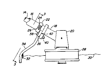
Fig. 2 is an enlarged side view ox the shield and its
mounting mechanism.
Jo

Fig. 3 is a enlarged view of the shield and it mounting
mechanism taken along lines 3~-3 of Fly. 2.
Description ox the Preferred Embodiment
Looking now to Fig. I, there it illustrated a string
trimmer or trimmer 10 lying on its side a it would be during
transport. The trimmer 10 includes an engine 12, that engine
12 being gas powered in thy preferred embodiment; however, an
electric power source could be provided. The engine 12 drives
a power shaft 14 which extends through the sleeve or tube
designated 16. The tube 16 is clamped to a die-cast extension
or casting 18 which is connected at an angle with the gear box
or trimmer head 20. A clamp 22 secures the catting 18 to the
tube 16, through use of bolts 24 and nuts 26. The gear box 20
carries a cutter head 28 wherein string 30 (nylon or other co-
polymer) is mounted as the preferred cutting element. A knife
or line limiter 32 is carried by a shield 34 which is mounted
to the casting 18.
Looking now to Fig. 2, there is better illustrated the
mounting structure for carrying the trimmer shield 34. The
die-cast extension 18 carried on the gear box 20 includes a
elite mounting surface 36 with a pair of openings or receiving
bolts 38 that would project through compatibly sized and
placed openings formed in the shield 34. The bolt 33 are
secured with nuts 40, as best illustrated in Fig. 2.
The mounting surface 36 carried on the die-cast portion
18 ox the gear box 20 and the mounting surface 42 carried on
the shield are oriented perpendicular to the sleeve or tube
16, as best illustrated in Figs. 1 and 2. The shield 34,
which is generally flat, is carried substantially
perpendicular to the shaft 14 when mounted. Therefore,
placement ox the trimmer 10 on the ground or in a trunk or bed
of a truck would result in the shield 34 being positioned as
illustrated in Fig. 1 and the forces encountered by the shield
34 as it supports the weight of the trimmer head 20, tube 16,
and engine 12 and any other object placed upon the trimmer
would be substantially perpendicular to the shield where it
mounts to the tube 16. Accordingly, bending forces, which

- 2~32~7
could serve to weaken and f final lye cause a fracture in the
shield 34 are minimized.
.

Representative Drawing
A single figure which represents the drawing illustrating the invention.
Administrative Status

2024-08-01:As part of the Next Generation Patents (NGP) transition, the Canadian Patents Database (CPD) now contains a more detailed Event History, which replicates the Event Log of our new back-office solution.

Please note that "Inactive:" events refers to events no longer in use in our new back-office solution.

For a clearer understanding of the status of the application/patent presented on this page, the site Disclaimer , as well as the definitions for Patent , Event History , Maintenance Fee  and Payment History  should be consulted.

Event History

Description Date
Inactive: IPC from MCD 2006-03-11
Application Not Reinstated by Deadline 1994-11-24
Time Limit for Reversal Expired 1994-11-24
Inactive: Adhoc Request Documented 1994-05-24
Deemed Abandoned - Failure to Respond to Maintenance Fee Notice 1994-05-24
Application Published (Open to Public Inspection) 1992-01-26
All Requirements for Examination Determined Compliant 1991-05-24
Request for Examination Requirements Determined Compliant 1991-05-24

Abandonment History

Abandonment Date Reason Reinstatement Date
1994-05-24
Owners on Record

Note: Records showing the ownership history in alphabetical order.

Current Owners on Record
DEERE & COMPANY
Past Owners on Record
JAMES J. HARTWIG
Past Owners that do not appear in the "Owners on Record" listing will appear in other documentation within the application.
Documents

To view selected files, please enter reCAPTCHA code :


To view images, click a link in the Document Description column. To download the documents, select one or more checkboxes in the first column and then click the "Download Selected in PDF format (Zip Archive)" or the "Download Selected as Single PDF" button.

List of published and non-published patent-specific documents on the CPD .

If you have any difficulty accessing content, you can call the Client Service Centre at 1-866-997-1936 or send them an e-mail at CIPO Client Service Centre.


Document
Description 
Date
(yyyy-mm-dd) 
Number of pages   Size of Image (KB) 
Cover Page 1992-01-26 1 13
Claims 1992-01-26 1 44
Abstract 1992-01-26 1 19
Drawings 1992-01-26 1 30
Descriptions 1992-01-26 4 164
Representative drawing 2002-07-29 1 8
Fees 1993-05-21 1 37