Language selection

Search

Patent 2043381 Summary

Third-party information liability

Some of the information on this Web page has been provided by external sources. The Government of Canada is not responsible for the accuracy, reliability or currency of the information supplied by external sources. Users wishing to rely upon this information should consult directly with the source of the information. Content provided by external sources is not subject to official languages, privacy and accessibility requirements.

Claims and Abstract availability

Any discrepancies in the text and image of the Claims and Abstract are due to differing posting times. Text of the Claims and Abstract are posted:

  • At the time the application is open to public inspection;
  • At the time of issue of the patent (grant).
(12) Patent: (11) CA 2043381
(54) English Title: ELECTROSTATIC SPRAY APPARATUS
(54) French Title: APPAREIL DE PROJECTION ELECTROSTATIQUE
Status: Expired and beyond the Period of Reversal
Bibliographic Data
(51) International Patent Classification (IPC):
  • B05B 05/03 (2006.01)
  • A21B 03/16 (2006.01)
  • B05B 01/06 (2006.01)
  • B05B 05/12 (2006.01)
  • B05B 07/00 (2006.01)
  • B05B 07/06 (2006.01)
  • B05D 01/04 (2006.01)
  • B05D 07/22 (2006.01)
(72) Inventors :
  • WOOLLARD, DOUGLAS J. (United Kingdom)
(73) Owners :
  • CEREFORM LIMITED
(71) Applicants :
  • CEREFORM LIMITED (United Kingdom)
(74) Agent: MARKS & CLERK
(74) Associate agent:
(45) Issued: 2000-12-05
(22) Filed Date: 1991-05-28
(41) Open to Public Inspection: 1991-12-02
Examination requested: 1998-04-29
Availability of licence: N/A
Dedicated to the Public: N/A
(25) Language of filing: English

Patent Cooperation Treaty (PCT): No

(30) Application Priority Data:
Application No. Country/Territory Date
9012307.6 (United Kingdom) 1990-06-01

Abstracts

English Abstract


An electrostatic spray apparatus comprises a
source of electrostatically charged liquid connected to an
annular nozzle which discharges a hollow tube of
electrostatically charged liquid, a source of atomizing air
under pressure, an annular atomizing air discharge nozzle
surrounding the liquid discharge nozzle, and an annular
swirl chamber for the atomizing air. A plurality of
apertures connect the source of air to the swirl chamber,
the apertures being oriented at an angle to the radial
direction to initiate a substantially tangential swirling
flow of air in the chamber and being disposed to allow air
to pass radially outwardly into the chamber. The chamber
is defined by walls which tend to converge in an axial
direction from the plurality of apertures towards the air
discharge nozzle.


Claims

Note: Claims are shown in the official language in which they were submitted.

THE EMBODIMENTS OF THE INVENTION IN WHICH AN EXCLUSIVE
PROPERTY OR PRIVILEGE IS CLAIMED ARE DEFINED AS FOLLOWS:
1. An electrostatic spray apparatus comprising a source
of liquid, an annular nozzle having a central axis and
connected to the source of liquid for discharging a
hollow tube of electrostatically charged liquid, a source
of atomizing air under pressure, an annular atomizing air
discharge nozzle surrounding said liquid discharge
nozzle, an annular swirl chamber for said atomizing air,
and a plurality of apertures connecting said source of
air to said swirl chamber, each of said apertures being
oriented at an angle to a radial direction relative to
the central axis to initiate a substantially tangential
swirling flow of air in the chamber characterized in that
said apertures are disposed to allow air to pass radially
outwardly into said chamber, said swirl chamber being
defined by walls which tend to converge in an axial
direction from said plurality of apertures towards said
air discharge nozzle, and said source of liquid is
electrostatically charged.
2. A spray apparatus according to claim 1, wherein the
liquids is oil or an oil containing composition.
3. A spray apparatus according to claim 1 or claim 2,
wherein said swirl chamber decreases in median radial
diameter from said plurality of apertures towards said
air discharge nozzle.
4. A spray apparatus according to claim 1, wherein the
source of atomizing air is at a pressure in the region of
68.95 KN/m2(10 psi).
5. A spray apparatus according to claim 1, wherein the
source of liquid is at a pressure in the range of 27.58
KN/m2 to 82.74 KN/m2.
6. A spray apparatus according to claim 1, wherein the
source of liquid is electrostatically charged by means of
a charge of 50,000 volts.
7. A spray apparatus according to claim 6, wherein the
source of liquid is charged at a rate of 100 microamps.
8. A spray apparatus according to claim 1, wherein the
liquid is a release oil composition.

Description

Note: Descriptions are shown in the official language in which they were submitted.


20~338~
- 1 -
ELECTROSTATIC SPRAY APPARATUS
The present invention relates to an electrostatic
spray apparatus, and also to a method of coating the
interior of containers with an electrostatically charged
liquid. The invention is particularly, but not
exclusively, directed to the spraying of electrostatically
charged oil into containers for baking bread and other
confectionery.
The invention will be described with reference to
its use in coating baking tins with oil to release
subsequently baked items of confectionery or loaves.
However, other uses can be foreseen and it is not intended
that they are excluded from protection by virtue of
reference only to coating baking tins with oil described
particularly in this application.
It is well known that bread baking tins should be
coated with a release agent such as oil prior to the
insertion of dough therein. It is particularly important
to coat the sides of the tin to enable removal of the baked
loaf. Hitherto, this has been accomplished by simple
spraying of a jet of atomized oil. However, this suffer;:
from the disadvantage that a fog of oil particles is
created, and this fog is injurious to the health of
operatives, and where it settles, may cause slippages and
accumulation of dirt. As production line speeds have
increased, the pressure needed to spray the oil within the

- 2 - 204339..
shorter time period allowed has increased, and increased
pressure leads to increased fogging. One solution to this
problem is to charge the oil electrostatically so that,
when it contacts the metal of the baking tin, there is no
rebound. This lessens the concentration of oil particles
in the atmosphere surrounding the baking tin. However,
this is not a complete solution, since the optimum
distribution of oil is on the side of the baking tin'rather
than an overall coating within the container. For this
purpose, it is desirable that the jet of atomized charged
oil particles is emitted from the apparatus in the form of
as flat a cone as may be practicable.
It is an object of the present invention to
provide an apparatus which overcomes or obviates to a large
degree the above disadvantages and also to provide a method
of use of such an apparatus.
FR-A-2319425 discloses an electrostatic spray
apparatus for spraying paints comprising a source of
liquid, an annular nozzle connected thereto for discharging
a hollow tube of electrostatically charged liquid, a source
of atomizing air under pressure, an annular atomizing air
discharge nozzle surrounding the liquid discharge nozzle,
an annular swirl chamber for the atomizing air, and a
plurality of apertures connecting the source of air to the
swirl chamber, the apertures being oriented at an angle to
the radial direction to initiate a substantially
tangential swirling flow of air in the chamber.
However, in FR-A-2319425, the apertures are
disposed to allow air to pass in a radially inward
direction into the chamber, and thus, for any chosen
overall diameter of spray apparatus, the inlet diameter of
the swirl chamber is limited by the need to accommodate the
air supply passages and the apertures outside the swirl
chamber. Limiting the inlet diameter of the swirl chamber
limits the ratio of inlet diameter to outlet diameter of

2043381
' - 3 -
the swirl chamber and this in turn limits the angle at
which the atomizing air leaves the nozzle, and thus
limits the conic angle of the liquid spray.
According to a first aspect of the present invention
there is provided an electrostatic spray apparatus
comprising a source of liquid, an annular nozzle having a
central axis and connected to the source of liquid for
discharging a hollow tube of electrostatically charged
liquid, a source of atomizing air under pressure, an
annular atomizing air discharge nozzle surrounding said
liquid discharge nozzle, an annular swirl chamber for
said atomizing air, and a plurality of apertures
connecting said source of air to said swirl chamber, each
of said apertures being oriented at an angle to a radial
direction relative to the central axis to initiate a
substantially tangential swirling flow of air in the
chamber characterized in that said apertures are disposed
to allow air to pass radially outwardly into said
chamber, said swirl chamber being defined by walls which
tend to converge in an axial direction from said
plurality of apertures towards said air discharge nozzle,
and said source of liquid is electrostatically charged.
Preferably the liquid is oil or an oil containing
composition, advantageously a release oil composition,
optionally for use with baking tins of bread or other
confectionery.
The swirl chamber preferably decreases in median
radial diameter from the plurality of apertures towards
the air discharge nozzle.
The source of atomizing air may be at a pressure in
the region of 68.95 KN/m2 (10 psi).
The source of liquid may be at a pressure in the
region of 27.85 KN/m2 to 82.74 KN/m2 (4 to 12 psi) .
The liquid may be electrostatically charged by means
of a charge of 50,000 Volts, optionally at a current

_ - 4 - ~~43~8~.
of 100 microamps.
According to a second aspect of the present
invention there is provided a method of coating the
interior of open containers with oil or similar liquid
comprising the steps of passing the containers adjacent at
least one electrostatic spray apparatus of the first aspect
of the invention, the apparatus being located within a
distance in the region of 10 to 20 mm from the open ,face of
the container, sensing the presence of a container and in
response thereto, enabling flow of electrostatically
charged oil and atomizing air to create a hollow
substantially conical zone of charged atomized oil
particles directed towards the interior of the container.
Preferably the open containers are baking tins
for bread or confectionery products, and the oil is a
release oil composition to enable the product deposited
therein subsequently to the coating to be removed from the
tins when baked.
The step of enabling flow of electrostatically
charged oil and atomizing air may be carried out for a time
in the region of 50 to 300 msecs for each container.
In this case, the means to sense the presence of
a container may enable a supply of air or other fluid at a
comparatively high pressure to act on piston means, said
piston means opening, immediately sequentially, valves to
supply atomizing air and electrostatically charged oil.
In the case of cuboidal baking tins, it is
preferred to have two spray apparatus, one disposed
adjacent each end of the container.
An embodiment of the present invention will now
be more particularly described by way of example and with
reference to the accompanying drawings, in which:
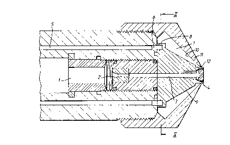
Figure 1 is a schematic longitudinal cross-
sectional view of an end of a spray apparatus embodying the
invention; and

- 5 - ~~43~~~..
Figure 2 is a cross-sectional view taken on line
II-II of Figure 1.
Referring now to Figure 1, there is shown a
spray head having an oil reservoir 1, to which an oil
composition is supplied at a pressure in the region of
27.58 KN/m2 to 82.74 KN/m2 (4 to 12 psi) and which is
charged to minus 50,000 Volts and at a maximum current of
100 microamps. The oil reservoir 1 is closed by means of a
needle (not shown) fitting in a needle seat 2. When the
needle is withdrawn, oil may flow through passage 3 to an
annular nozzle 4. This nozzle has a gap in the region of
0.35 mm or less. Oil exiting from this nozzle forms a
hollow tube.
A supply of atomizing air is supplied at a
pressure in the region of 68.95 KN/m2 (10 psi) to an
annular chamber 6 by means of a number of channels 5. From
this annular chamber 6, lead a number of apertures 8 so
disposed that the compressed air may flow radially
outwardly into a swirl chamber 7 as can be more clearly
seen in Figure 2. The apertures 8 are angled substantially
equally so that the air exiting therethrough assumes a
tangential flow within the chamber 7.
The swirl chamber 7 is defined between an outer
wall 9 of the oil discharge system and an inner wall 10 of
a nozzle cap 11. Walls 9 and 10 converge from the
apertures 8 to an air discharge nozzle 12. This air
discharge nozzle 12 emits a tube of rapidly swirling air
into a zone immediately surrounding the emitted tube of
charged oil. Interaction between these tubes causes the
oil to be atomized and sprayed into a conic form by virtue
of the swirling effect of the air. Because the air flows
radially outwardly into the swirl chamber 7 through
apertures 8 the inlet diameter of the swirl chamber is only
limited by the overall diameter of the nozzle head, and
therefore the possible range of ratios between the inlet

- 6 - ~~43~~~.
and outlet diameters of the swirl chamber is maximized,
which results in greater versatility in the conic angle of
the oil spray
The shape of the swirl chamber 7 is such that the
air emitted therefrom has a very high angular velocity at
nozzle 12 without the air being supplied at a very high
pressure. Accordingly, the cone of atomized oil particles
formed by the apparatus has a cone angle in the region of
60° to 700. This enables the apparatus to be placed closer
to the containers to be coated and still coat the sides
thereof, thereby reducing extraneous deposition of oil.
The apparatus may be used in coating baking tins interiorly
with release oil composition by passing the tins beneath a
pair of such spray heads. For each tin, a spray time of 50
to 300 msecs may be allowed, during which time 0.4 to 1.0 g
of oil may be deposited on the interior of the tin. The
tins pass beneath the spray heads with a clearance of a
distance in the region of 10 to 20 mm and this short
distance, combined with the electrostatic charging of the
oil particles, ensures that a minimum amount of oil is
deposited exteriorly of the tins.
The presence of a tin to be sprayed is determined
by a sensor, such as a proximity sensor or trip switch.
This actuates a comparatively high pressure (e. g. 80 psi)
air source which acts on a piston firstly to allow a flow
of atomizing air to channels 5 and then, immediately
subsequently, to withdraw the needle from the needle seat 2
to allow the flow of oil from the reservoir 1. In this
way, flow rates of over 8000 tins per hour may be
achieved.

Representative Drawing
A single figure which represents the drawing illustrating the invention.
Administrative Status

2024-08-01:As part of the Next Generation Patents (NGP) transition, the Canadian Patents Database (CPD) now contains a more detailed Event History, which replicates the Event Log of our new back-office solution.

Please note that "Inactive:" events refers to events no longer in use in our new back-office solution.

For a clearer understanding of the status of the application/patent presented on this page, the site Disclaimer , as well as the definitions for Patent , Event History , Maintenance Fee  and Payment History  should be consulted.

Event History

Description Date
Time Limit for Reversal Expired 2010-05-28
Letter Sent 2009-05-28
Inactive: IPC from MCD 2006-03-11
Letter Sent 2005-03-07
Change of Address or Method of Correspondence Request Received 2005-02-09
Inactive: Single transfer 2005-02-09
Grant by Issuance 2000-12-05
Inactive: Cover page published 2000-12-04
Inactive: Final fee received 2000-08-31
Pre-grant 2000-08-31
Letter Sent 2000-04-06
Notice of Allowance is Issued 2000-04-06
Inactive: Approved for allowance (AFA) 2000-03-27
Inactive: Correspondence - Formalities 1999-02-05
Letter Sent 1998-06-12
Inactive: Status info is complete as of Log entry date 1998-06-08
Inactive: Application prosecuted on TS as of Log entry date 1998-06-08
All Requirements for Examination Determined Compliant 1998-04-29
Request for Examination Requirements Determined Compliant 1998-04-29
Application Published (Open to Public Inspection) 1991-12-02

Abandonment History

There is no abandonment history.

Maintenance Fee

The last payment was received on 2000-04-28

Note : If the full payment has not been received on or before the date indicated, a further fee may be required which may be one of the following

  • the reinstatement fee;
  • the late payment fee; or
  • additional fee to reverse deemed expiry.

Patent fees are adjusted on the 1st of January every year. The amounts above are the current amounts if received by December 31 of the current year.
Please refer to the CIPO Patent Fees web page to see all current fee amounts.

Owners on Record

Note: Records showing the ownership history in alphabetical order.

Current Owners on Record
CEREFORM LIMITED
Past Owners on Record
DOUGLAS J. WOOLLARD
Past Owners that do not appear in the "Owners on Record" listing will appear in other documentation within the application.
Documents

To view selected files, please enter reCAPTCHA code :


To view images, click a link in the Document Description column. To download the documents, select one or more checkboxes in the first column and then click the "Download Selected in PDF format (Zip Archive)" or the "Download Selected as Single PDF" button.

List of published and non-published patent-specific documents on the CPD .

If you have any difficulty accessing content, you can call the Client Service Centre at 1-866-997-1936 or send them an e-mail at CIPO Client Service Centre.


Document
Description 
Date
(yyyy-mm-dd) 
Number of pages   Size of Image (KB) 
Abstract 1994-01-12 1 21
Claims 1994-01-12 3 71
Description 1994-01-12 6 224
Drawings 1994-01-12 2 47
Description 1998-06-28 6 263
Drawings 1998-06-28 2 58
Claims 1998-06-28 1 49
Representative drawing 1999-07-06 1 27
Representative drawing 2000-11-06 1 20
Reminder - Request for Examination 1998-01-28 1 118
Acknowledgement of Request for Examination 1998-06-11 1 178
Commissioner's Notice - Application Found Allowable 2000-04-05 1 164
Courtesy - Certificate of registration (related document(s)) 2005-03-06 1 105
Maintenance Fee Notice 2009-07-08 1 171
Correspondence 1991-09-15 3 113
Correspondence 2000-08-30 1 49
Correspondence 1999-02-04 1 34
Correspondence 2005-02-08 2 93
Fees 1997-04-21 1 69
Fees 1996-04-25 1 60
Fees 1995-04-23 1 52
Fees 1994-04-14 1 49
Fees 1993-04-15 1 41