Note: Descriptions are shown in the official language in which they were submitted.
2~37~
A ~r~e~;s w~ ~ (levic~e for ~o~ting moto~ ~istons
~l~he inVentiOJI relate~ to a process and a device for coatillg
the cylindrical surface of engine pi~tons or slmilar with
co~tillg comp~und, in partieular slippery pastes.
Such a coatlng o~' piston surfaces, which norm~lly represents
a lea~, tln, grapllite or similar coating in a determined
thicliness, is ~erformed with pistons so as to prevent the
seizing of the pist~ns in the event of a fallure in the oil
lubrication in the cylinders of an internal combustion
engineand also to reduce the knocking of the engine if the
coating is effected in varying thicknesses and with a
varyin~ coating pattern.
Hitherto the coating of engine pistons has generally been
applied by spraying, which is expensive and unsatisfactory
because of high losses and low efficiency. Furthermore
spraying is detriment~l to the en~ironment as large
quantities of solvents are atomised.
As the peripheral surfaces of the pistons are coated via
masks when spraying, no sharp contours of the coating
surfaces can be re~ched. In addition the spray mist c~uses
undefinable coating contours under the spraying masks which
are not clo~e together. Furthermore the thic~ness of the
coatin~, whicll is determlned by adjusting the spray noz~le,
normally ilas large tolerances.
:~0
'l'he o~ject o~' tlle invention is therefore to create a process
alld a device ~'or coating the cylindri~al periphery of englne
pi~tOIlS ~r similar with coating compound, by which the
a~o~e-~lelltiol-led pre~iously e~isting de~'iciencies are removed
3~ with relatively ~imple requirements with respect to the
pr~cesses and stru~ture. lt should also ~e possi~le to
reproduo~ tlle r~ulre~ ooatillg thic,~nes~ ~as~ on
~Ledet~rmined value~ at ~ny time for different ~i~tons.
'l'his o~ject is achieve~ as s~eoifie~ ~y the invention ~y
co~ting ~eing performe~ by means of screen ~rinting.
With this s~reen printing coating a uniform coating with
minimum tol~ranc,es can be rationally applied to the
cy1inclrical perlpheral surfaces of engine plstons or
simil~r, with every environmentally damaging emission, such
as, fc,r e~am~le, solvent evaporation, being completely
exc,lude~. ~ith this process lt is also possible to apply
several l~yers of the same or different thicknesses on top
of one another in one process sequenc,e. If the viscosity of
the coatiny compound remains constant, the thickness of the
COatillg 011 the peripheral surface of the piston can be
predetermine~ via the quality of the woven cloth of the
screen ~rinting ~tencil.
With the proc,ess specified by the invention one or several
uncoated free areas can also advantageous1y ~e provided in
a coated surface as lubrication bore reliefs and/or as
observation ports in the form of slits, holes, recesses,
strips OL- similar. Such free areas perform a double
function. Firstly they serve as measurement holes or
observation ~orts f or the measurement an~ consequently the
monitoring of the coating thickness and secondly they
im~rove tl~e lu~rication of the ~iston in normal o~eration,
as they clC,t as grease ~earings. ln contrast to known
sprayiny methocls, in the screen printing process s~ecifie~
~y the inventioll such free areas can simply and without
great e~pelldlture ~e produced in aJly size ancl form with very
precise tolerances for thickness and edge contours. 'l'his
applies especially for very sma11 free areas.
~ 3~
~ith the ~rocess s~ecifie~ ~y the 'inventlon the ~lstons are
expedielltly ooateci in the upright ~osition alld arc)url~ their
.
:
- 2 ~
ver~ el-lt~ n~ltu~inal ~is whil~t they rot~te ~t
a ~rint~ pres~ stencil whilst a~utting said ~tencil, with
the seL~en pL-inting stencil also being moved in the
~iLecti~n ol rotatioll ot the ~eripheral surface of the
pi~t~
~ coul-se it is also possi~le for the pistons to have a
horizollt~l arrangement of the pistons for coatlng, as for
e~ample in experiments and with small loads.
1()
~lhe coatln~ is advalltageously applied in a wedge shape with
the coatill~ thickness decreasing at its lateral and/or upper
and lowel- e~ges. As a result of this measure, hard edges or
steps are avoided and the coated surface is smoother. In
lS this w~y a better adaptation to the rounded shape of the
piston is achieved in particular and correspondingly strong
resistance is avoided. This is true in particular for the
lateral edges, but this is also advantageous for the upper
and lower edge with respect to the direction of movement of
the piston. trhe coating compound can be brought to the
screen printing stencil of the screen printing unit whilst
it is continually rotated and mixed together.
The invention also relates to a device for performing the
screen printing coating process, which is characterised in
that it comprises one OL- several screen printing statlons
each having a screen printing stencil and an applicator
bla~e, up to the screen printing stencil of which the
pistons to be coated in receptacles supporting them can be
moved with their cylindrical peripheral surface to ~e
coated, ln that the pistons with their receptacles in said
position can ~e rotated around the central longitudinal axes
of the pistons, with it at the same time ~eing ~osslble to
entrain the printing stencil tangentially thereto and
without slippillg in the directlon of rota~ion of the
~eri~her~l surface of the piston, and in that the applicator
-' '
' '
~ 3 ~ i~ fl
~lade with its ~la~e ed~e extending parallel to the central
lon~itudin~l axis o~' th~ piston to be coated is positioned
o~osite the ~eri~heral surface of the piston a~utting the
~r~n ~rintiny stencil during the printing operation. 'l'he
5 pistons may ~e dis~osed so that they are upright or lying
hori~ontally.
Ilowever provision will be advantageously made so that the
screen printing stencil and the applicator blade extend
vertically an~ that the pistons are disposed vertically on
the receptacles.
The hardness o~'the blades may be adapted to the re~uired
thickness of the coating to be applied. If there are
provided several screen printing stations disposed one
behind the other in the path of the pistons to be coated,
the blades of these stations may have the same or different
hardness.
In the drawings there is shown a particularly advantageous
exemplified em~odiment of a coating device and a coating to
be pr~duced therewith, which is described in greater detail
below.
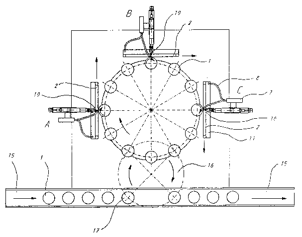
: 25 Figure 1 shows a lateral view of a coating device,
l~'igure 2 shows a plan view of the coating device shown
in l~'ig. 1,
l~igure 3 sl-lows an exem~lifie~ em~odiment of the coating
to ~e achieved with the process specifie~ by
the invention and with the device ~pecified by
the inventioll on the peri~heral surface of a
~iston,
: 3~
l'iyure 4 shows the exem~ ied em~odiment shown in
l~`iyure 3 in a position off6et by ~0 thereto,
..
.. .
~ r~L37~
l'iyure ~ shows ~n enlarge~ re~resentation o~' a
perlpher~l region ~ ~ piston with ~oatiny
surf~es in lateral elev~tion,
l'igure ~ sh~w~ ~ rece~t~ole f~r a plston.
With the e~em~lified em~o~iment represented in the ~rawings
the piSt~ su~plie~ ~y a continuously rotating conveyor
~elt l~ Wit~l thelr centr~l longitudinal a~is X vertical are
rhythmic~lly removed from the conveyor belt by a rotating
hea~ l~ h.,ving tongs 17, which grasp the pistons 1 in their
grooves with jaws (not shown), and are transferred parallel
to one an~ther via a epicyclic gear system 9, 12A, 12~, 14A,
14~ to position-controlled receptacles 18, which are
dispose~ Oll a rotary table 13. The pistons 1 are held in
these re~eptacles 1~ so that they cannot rotate by upwardly
projecting pins 6, onto which the pistons 1 are placed, and
by rotating tha rotating table 13 they are brought up one
after the other by a step-by-step device to three screen
printing ~tations A, ~ and C lying behind one another in the
path of the pistons, in which stations they receive the
predetermine~ coatings Al, B1, Cl on their cylin~rical
surface one ~fter the other. The coatings are ap~lied by
means o~' s~reen prlnting stencils Z, which hy means of
applicatoL ~l~des lO come to tangentially a~ut the
peripheral sur~ace of the pistons to be coated~ During the
printing operation the pistons together with their
receptacles l~ ~erform to a rotation around their central
longitu~in~l axis X (Fig. ~ and 5), in which the printing
stencil ~ ~an ~e entr~ine~ without sli~piny in the ~irection
o~` rotation of the peripheral surf~ce o~ the pistons
tangelltially thereto. 'l'he arrows in Fig. ~ show the
~ire~tion of rot~tioll and ~irection of movement o~` the
peripheral suLface of the piStOIlS an~ of the s~reen printiny
' ' - ' '
, , ~ : , ~ ' '
~tencil ~ during the pril1ting operation. ~uring thi~ the
ap~licat~L ~lade remains with itS ~lade edge extending
parallel to the celltral longitudinal axis X of the piston 1
t~ be coate~ o~posite the peripheral surface of the piston
a~uttill~ th~ screell printing ~tencil and at the same tlme
carries tlle c~ating com~ound su~lied to the upper region of
the screell ~Linting ~tencil via a hose line 8 through the
stellcil Lo tlle periplleral surface of the pistons.
Just one ~art of the peripheral surface of the piston can be
coated, ~epending on the design of the ~creen printing
stencil. Ln the exem~lified embodiment shown in Figures 3 to
5, the piston 1 is provided at its piston hea~ with a
circular coating C3 by the screen printing station C and in
the region of the periphery of the piston just on the sides
offset to the piston pin bore 3 with coatings for coating
surfaces Al, B1, Cl ~y coating stations A, B, C.
The coating surfaces shown in the exemplified embodiment are
naturally only given as examples. ln many cases fewer
coating surfaces are adequate. Thus, for example, only two
lower coating surfaces Al may be provided, which are located
opposite one another and extend over a peripheral region of
ap~rox. 90 . The two coating surfaces Al may he provided as
bufers, for example, for the reduction of the knocking by
the engine and may have a coating thickness of 10 ~m.
Two coating surfaces Cl, which are also located opposite one
another and are mutually spaced and disposed parallel to
coating surfaces Al and also possi~ly coating surfaces Bl
may be ~rovided in particular for emer~ency lubrlcation in
the event of the failure of the normal lu~rication system.
Coating surtaces Cl (and possi~ly Bl~ may also extend over
a peripheral region of 90 an~ may have a thic~ness o~ 20
3~ ~m, for e~am~le.
- , ~
/
As can ~e seen ~rom ~ uLe ~, the ~ting su~es Al, ~1
~nd C 1 ~orm ~ we~e ~ha~e 4 at their e~es.
As can ~e seen from l~igure 3 ~n~ the enlar~ed represent~tio
in ~igure 4, the ~oatin~ surfaces ~an ~e provided with small
unco~ted free ~reas 5. F~r this purpose rectangular,
e1li~soi~1 all~ round recesses 5, for example, are drawn in
the ~oating surfaces Al and Cl. Of course further coating
surfaces having correspon~ing free ~r~as may be provi~ed,
lo for exam~le in the for~ of holes, s1its, strips, ellipses,
ovals, circles or similar.
Graphite powder having a resinous binding agent or a resin
is used as the coating compoun~ q'he following proportions
have prove~ successful for the mixture:
Graphite 30 - 50 ~ by weight, preferably 40 ~
Resin 50 - 70 % by weight, preferably 60 'Q6.
The viscosity o~ the coating compound should lie within a
range of from 6,~00 - 8,500 cp. Very good results are
achieved with a viscosity of approximately 7,000 cp.
I'o regulate or if necessary change th~ viscosity,
isopropan~1 or ethylglycol have proved to ~e successful.
The excess coating compoun~ running off the screen prin-tlng
stencil is collected in a storage vat 11 locate~ under the
stencil and is supplled by means of a pump 7 via a hose line
~ while ~eing contlnually mixed back to the screen printing
stencil. ~y the mi~ing and the continuous supply o~ the
screen printin~ compound it is possi~le to ~revent the
tendellcy of the coatirlg compound to challge its viscosity ~y
decompositi~
3~
After the en~ of the coatiJlg a~lication the ~la~e 10 is
with~rawll fr~m the screen ~rinting stencil 2, ~s ~ result of
,
,
whicl~ thL~ loses contact with the coated peripheral surface
ol the ~ on ~o that the screen printing stencil can ~e
with~rawll out of contact with the piston into its tan~ential
initial ~o~ition.
~fter the coating of thP pistons has been effected in the
three screen printing stations A, ~ an~ C, they are returned
to the rotary head 16 and removed via its tongs 17 from the
receptacles 1~ by being lifted off and conveyed on the
conveyor ~elt 15 to be transported away.
, , - . . . :
-
- ..... : . . :
.