Language selection

Search

Patent 2043899 Summary

Third-party information liability

Some of the information on this Web page has been provided by external sources. The Government of Canada is not responsible for the accuracy, reliability or currency of the information supplied by external sources. Users wishing to rely upon this information should consult directly with the source of the information. Content provided by external sources is not subject to official languages, privacy and accessibility requirements.

Claims and Abstract availability

Any discrepancies in the text and image of the Claims and Abstract are due to differing posting times. Text of the Claims and Abstract are posted:

  • At the time the application is open to public inspection;
  • At the time of issue of the patent (grant).
(12) Patent: (11) CA 2043899
(54) English Title: BONNET NUT WITH IMPROVED SAFETY CHARACTERISTICS
(54) French Title: BOULON DE CHAPEAU A CARACTERISTIQUE DE SECURITE AMELIOREE
Status: Expired
Bibliographic Data
(51) International Patent Classification (IPC):
  • F16K 31/126 (2006.01)
  • F16K 27/02 (2006.01)
(72) Inventors :
  • BREMERS, ALAN DAVID (United States of America)
  • OSGOOD, MELVIN LEW (United States of America)
(73) Owners :
  • FISHER CONTROLS INTERNATIONAL LLC (United States of America)
(71) Applicants :
  • FISHER CONTROLS INTERNATIONAL, INC. (United States of America)
(74) Agent: OSLER, HOSKIN & HARCOURT LLP
(74) Associate agent:
(45) Issued: 2001-08-28
(22) Filed Date: 1991-06-05
(41) Open to Public Inspection: 1991-12-07
Examination requested: 1998-06-02
Availability of licence: N/A
(25) Language of filing: English

Patent Cooperation Treaty (PCT): No

(30) Application Priority Data:
Application No. Country/Territory Date
07/534,518 United States of America 1990-06-06

Abstracts

English Abstract


A valve assembly includes a bonnet that is
captivated in a valve body stem mount by means of a
threaded bonnet nut. A pair of opposed pry holes are
formed in the bonnet at a point above the top of the
fully seated bonnet nut. Loosening of the bonnet nut
enables a bonnet that is stuck in the body stem mount
to be pryed loose with a pry bar inserted in one or
both of the pry holes and levered against the top of
the bonnet nut. The bonnet holes also provide a visual
indication of movement of the bonnet and whether there
is pressure in the valve body.


Claims

Note: Claims are shown in the official language in which they were submitted.


THE EMBODIMENTS OF THE INVENTION IN WHICH AN EXCLUSIVE
PROPERTY OR PRIVILEGE IS CLAIMED ARE DEFINED AS FOLLOWS:


1. A high pressure valve comprising:
a body;
a bonnet;
seal means for sealing said bonnet to said valve body;
a bonnet nut for securing said bonnet in said body; and
means including an aperture in said bonnet above said
bonnet nut to permit levering of said bonnet against said
bonnet nut by a suitable tool means cooperating with said
aperture when said bonnet nut is loosened relative to said body
for permitting said bonnet when said bonnet is stuck in said
body to be pried loose from said body for easy disassembly of
said bonnet from said body.
2. The valve of claim 1, wherein said bonnet nut and
said body are threadingly engaged over a distance sufficient
to permit said bonnet nut to be safely loosened to the level
of said aperture when said body is under pressure.
3. The valve of claim 2, wherein said bonnet nut
comprises a hammer lug type and wherein a pair of opposed
apertures are provided in said bonnet.
4. A high pressure valve assembly comprising:
a body having a cylindrical stem mount;
an exterior threaded portion on the end of said
cylindrical stem mount;
a cylindrical bonnet having a seal for sealing engagement
with said cylindrical stem mount;
a bonnet nut securing said bonnet in said cylindrical stem
mount by means of an internally threaded portion; and
a pry hole in said bonnet located above the top surface
of said bonnet nut, said pry hole permitting levering of said
bonnet against said bonnet nut by a suitable tool means
cooperating with said pry hole when said bonnet nut is loosened
relative to said body to free said bonnet from said body when
said bonnet is stuck in said body.


5. The valve assembly of claim 4, wherein a pair of
diametrically opposed pry holes are provided in said bonnet and
wherein said internally threaded portion of said bonnet nut
extends over a distance sufficient to secure said bonnet to
said cylindrical stem mount while permitting said seal to be
removed from sealing engagement with said cylindrical stem
mount.

Description

Note: Descriptions are shown in the official language in which they were submitted.


~~~389~
-1- 21-56(10720)A
BONNET HUT WITH IMPROVED SAFETY CHARACTERISTICS
Background of the Invention and Prior Art
This invention relates generally to high
pressure valves and particularly to bonnet securing
systems For high pressure control valves.
It is common practice to provide a valve body
with a removable bonnet that is maintained in a
captivated relationship with the valve body stem mount
by means of a bonnet nut. The bonnet is generally
cylindrical as is the valve body stem mount, and an 0
ring or the like provides the seal between the bonnet
and stem mount. A shoulder on the bonnet is engaged by
a bonnet nut that is threaded on the end of the stem
mount. The bonnet nut may be of the hammer lug type,
i.e. have a pair of external lugs to facilitate removal
and tightening thereof in heavy duty installations.
A problem that often arises, usually after
years of field service or service with corrosive medium
fluids, is that the bonnet sticks in the stem mount and
is not easily removable when the bonnet nut is removed.
Should the valve body be inadvertently left under
pressure, a dangerous situation may arise, since the
stuck bonnet may suddenly be blown loose when the
bonnet nut is removed. A prior art solution to the
problem of removing a bonnet that is stuck in the stem
mount is shown in FIG. 1, where a partial sectional
view of a bonnet nut and a valve body is shown. A
hammer lug type bonnet nut 10 having a pair of lugs 16
engages a shoulder portion of a bonnet 12 and maintains
it in position within a threaded stem mount 18. A
cylindrical hole 22 is formed in the side of bonnet nut
10 and is alignable with a cylindrical blind hole 20
(of similar size) formed in the side of bonnet 12. As
indicated, a pry bar 24, or similar tool, may be
inserted in both holes 22 and 20 to turn bonnet nut 10
and bonnet 12 together to break bonnet 12 loose from
stem mount 18. This prior art solution is awkward in


CA 02043899 2000-08-11
- 2 -
that the holes 20 and 22' must be aligned before the pry bar can
be used and there is no way to lever the bonnet 12 loose, apart
from turning it with bonnet nut 10.
Summarv of the Invention
In accordance with one embodiment of the present
invention there is provided a high pressure valve comprising:
a body: a bonnet: seal means for sealing the bonnet to the
valve body: a bonnet nut for securing the bonnet in the body:
and means including an aperture in the bonnet above the bonnet
nut to permit levering of the bonnet against the bonnet nut by
a suitable tool means cooperating with the aperture when the
bonnet nut is loosened relative to the body for permitting the
bonnet when the bonnet is stuck in the body to be pried loose
from the body for easy disassembly of the bonnet from the body.
In accordance with another embodiment of the present
invention there is provided a high pressure valve assembly
comprising: a body having a cylindrical stem mount; an exterior
threaded portion on the end of the cylindrical stem mounts a
cylindrical bonnet having a seal for sealing engagement with
the cylindrical stem mounts a bonnet nut securing the bonnet
in the cylindrical stem mount by means of an internally
threaded portion; and a pry hole in the bonnet located above
the top surface of the bonnet nut, the pry hole permitting
levering of the bonnet against the bonnet nut by a suitable
tool means cooperating with the pry hole when the bonnet nut
is loosened relative to the body to free the bonnet from the
body when the bonnet is stuck in the body.
Brief Description of the Drawincr
These and other features and advantages of the
30~ invention will be apparent upon reading the following
description in conjunction with the drawings, in which:
Fig. 1 is a partial sectional view of a prior art
bonnet and bonnet nut assembly;
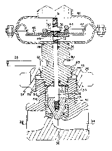
Fig. 2 is a partial view of a high pressure valve


CA 02043899 2000-08-11
- 2a -
incorporating the novel bonnet and bonnet nut assembly of the
invention; and
Fig. 3 i~ a sectional view of a portion of the valve
of Fig. 2 illustrating removal of a stuck bonnet.
Description of the Preferred Embodiment
Referring to Fig. 2, a high pressure control valve
has a valve body 30 with inlet and outlet ports 32 and 34,
respectively. The illustration is for a generally
cylindrically shaped bonnet 28 and a bonnet nut 26 in fully
assembled condition. A vertically movable valve plug 36 is
threadingly attached to a valve stem 38. Valve stem 38 passes
through an orifice in valve bonnet 28, the interior of which
may be equipped with O ring seals 54 or other well known type
of packing. A pair of jam nuts 52 cooperate with washers 48 and
50 and a threaded end 51 on stem 38 to~captivate a diaphragm
42 and a slightly disked diaphragm plate 46 therebetween.
Diaphragm 42 is conventionally supported in a diaphragm housing
40 and
2Ci


~a4~~99
-3- 21-56(10720)A
is loaded by a control spring 44. It will be
appreciated that the control portion of the valve as
well as the valve itself are conventional and may
comprise any well known construction, the present
invention being specifically directed to the bonnet,
the bonnet nut arid the bonnet removal means. A pair of
diametrically opposed blind holes 60 and 62 in bonnet
28 are located such that a distance 63 is provided
between the top of bonnet nut 26 and the holes 60 and
62. An 0 ring 56 in a suitable annular groove in
cylindrical bonnet 28 seals bonnet 28 to the stem mount
31 of valve body 30. The stem mount 31 of valve body
30 is threaded for engagement with a matching internal
thread 58 in bonnet nut 26. The tapered surfaces
between the inside of bonnet nut 26 and a shoulder 29
on the bonnet 28, indicated at A, helps to align the
bonnet 28 in stem mount 31~ A washer 53 and a cage 55
are forced by tightening movement of bonnet nut 26
against the bottom of valve body 30 to secure the
bonnet in the valve body. Valve plug 36 is movable in
cage 55 for controlling flow between inlet and outlet
ports 32 and 3~. This construction is well known and
has no bearing on the invention. A pry bar 24 or other
suitable tool may be inserted in either of holes 60 or
62 and levered against the top of a loosened bonnet nut
26 to free a stuck bonnet.
In FIG. 3, the bonnet nut is shown partially
loosened with the bonnet 28 being stuck in stem mount
31. In this condition, the seal with 0 ring 56 is
still intact, although a gap 64 exists between the
underside of the bonnet nut 26 and the tapered portion
on the upper side of shoulder 29 of bonnet 28. In this
condition, it is not known whether the valve body is
under pressure and the operator is at risk in
continuing removal of the bonnet nut. A pry bar 24 is
installed in hole 62 and may be used to lever the
bonnet 28 vertically upward with respect to stem mount


2~4~~~~s
-4- 21-56(10720)A
31 by applying downward pressure against the top of
bonnet nut 26. This breaks the bonnet loose in the
stem mount. If the valve body is under pressure, the
bonnet will be driven against bonnet nut 26, but will
still be securely retained in the valve stem. Removal
of the bonnet nut to the point where the 0 ring seal 56
clears the top of stem mount 31 breaks the seal.
Should the valve body 30 be under pressure, an audible
hiss will be perceived by the operator, warning of the
pressure condition.
It will also be appreciated that a visual
observation of the distance between holes 60 and 62 and
the top surface of bonnet nut 26 readily reveals that
the bonnet is stuck in the body since the distance 63
(FIG. 2) has become smaller as the bonnet nut is
loosened. If the distance 63 remains the same as the
bonnet nut 26 is loosened, it clearly indicates
movement of bonnet 28 out of stem mount 31 and that the
valve body is under pressure. Danger of the bonnet
being blown out exists in continuing to remove bonnet
nut 26 under a pressure condition. Shortly beyond this
point, the operator should also be hearing a hiss from
the escaping pressurized fluid. The extra long
threaded portion 58 of bonnet nut 26 enables the bonnet
nut to maintain sufficient holding strength to permit
the bonnet nut 26 to be loosened sufficiently to verify
the pressure condition and enable remedial action to be
taken.
It is recognized that numerous changes and
modifications in the described embodiment of the
invention will be apparent to those skilled in the art
without departing from its true spirit and scope. The
invention is to be limited only as defined in the
claims.

Representative Drawing
A single figure which represents the drawing illustrating the invention.
Administrative Status

For a clearer understanding of the status of the application/patent presented on this page, the site Disclaimer , as well as the definitions for Patent , Administrative Status , Maintenance Fee  and Payment History  should be consulted.

Administrative Status

Title Date
Forecasted Issue Date 2001-08-28
(22) Filed 1991-06-05
(41) Open to Public Inspection 1991-12-07
Examination Requested 1998-06-02
(45) Issued 2001-08-28
Expired 2011-06-05

Abandonment History

There is no abandonment history.

Payment History

Fee Type Anniversary Year Due Date Amount Paid Paid Date
Application Fee $0.00 1991-06-05
Registration of a document - section 124 $0.00 1991-11-22
Maintenance Fee - Application - New Act 2 1993-06-07 $100.00 1993-04-23
Maintenance Fee - Application - New Act 3 1994-06-06 $100.00 1994-05-31
Maintenance Fee - Application - New Act 4 1995-06-05 $100.00 1995-05-26
Maintenance Fee - Application - New Act 5 1996-06-05 $150.00 1996-05-23
Maintenance Fee - Application - New Act 6 1997-06-05 $150.00 1997-05-20
Maintenance Fee - Application - New Act 7 1998-06-05 $150.00 1998-05-25
Request for Examination $400.00 1998-06-02
Maintenance Fee - Application - New Act 8 1999-06-07 $150.00 1999-05-31
Maintenance Fee - Application - New Act 9 2000-06-05 $150.00 2000-05-30
Final Fee $300.00 2001-05-30
Maintenance Fee - Application - New Act 10 2001-06-05 $200.00 2001-06-04
Maintenance Fee - Patent - New Act 11 2002-06-05 $200.00 2002-05-16
Maintenance Fee - Patent - New Act 12 2003-06-05 $200.00 2003-05-20
Registration of a document - section 124 $50.00 2003-08-07
Maintenance Fee - Patent - New Act 13 2004-06-07 $250.00 2004-05-17
Maintenance Fee - Patent - New Act 14 2005-06-06 $250.00 2005-05-09
Maintenance Fee - Patent - New Act 15 2006-06-05 $450.00 2006-05-05
Maintenance Fee - Patent - New Act 16 2007-06-05 $450.00 2007-05-07
Maintenance Fee - Patent - New Act 17 2008-06-05 $450.00 2008-05-12
Maintenance Fee - Patent - New Act 18 2009-06-05 $450.00 2009-05-14
Maintenance Fee - Patent - New Act 19 2010-06-07 $450.00 2010-05-11
Owners on Record

Note: Records showing the ownership history in alphabetical order.

Current Owners on Record
FISHER CONTROLS INTERNATIONAL LLC
Past Owners on Record
BREMERS, ALAN DAVID
FISHER CONTROLS INTERNATIONAL, INC.
OSGOOD, MELVIN LEW
Past Owners that do not appear in the "Owners on Record" listing will appear in other documentation within the application.
Documents

To view selected files, please enter reCAPTCHA code :


To view images, click a link in the Document Description column. To download the documents, select one or more checkboxes in the first column and then click the "Download Selected in PDF format (Zip Archive)" or the "Download Selected as Single PDF" button.

List of published and non-published patent-specific documents on the CPD .

If you have any difficulty accessing content, you can call the Client Service Centre at 1-866-997-1936 or send them an e-mail at CIPO Client Service Centre.


Document
Description 
Date
(yyyy-mm-dd) 
Number of pages   Size of Image (KB) 
Claims 2000-08-11 2 57
Description 2000-08-11 5 203
Representative Drawing 1999-08-23 1 34
Cover Page 2001-08-16 1 46
Representative Drawing 2001-08-16 1 17
Abstract 1993-12-04 1 15
Cover Page 1993-12-04 1 14
Claims 1993-12-04 2 42
Drawings 1993-12-04 2 58
Description 1993-12-04 4 167
Prosecution-Amendment 2000-02-15 3 6
Fees 2001-06-04 1 54
Assignment 2003-08-07 5 115
Fees 1998-05-25 1 60
Prosecution-Amendment 1998-08-05 2 86
Fees 2000-05-30 1 54
Assignment 1991-06-05 5 172
Prosecution-Amendment 1998-06-02 1 55
Prosecution-Amendment 2000-08-11 7 235
Correspondence 2001-05-30 1 56
Fees 1999-05-31 1 56
Fees 1997-05-20 1 51
Fees 1996-05-23 1 51
Fees 1995-05-26 1 49
Fees 1994-05-31 1 53
Fees 1993-05-23 1 40