Note: Descriptions are shown in the official language in which they were submitted.
CORRECTING METHOD FOR DATA USED FOR
CONTROL OPERATION OF VEHICULAR CLUTCH
BACKGROUND OF THE INVENTION
Field of the Invention
The present invention relates to a method for
eorrecting data used for controlling the operation of a
vehicular eluteh, and more partieularly to a method for
eorreeting learned data for clutch control operation.
Description of the Prior Art
In the prior art there has been widely used a elutch
control system for controlling the operation of a friction
type cluteh in which the clutch is coupled with an actuator
and the amount of operation of the elutch is controlled by the
actuator in aceordanee with an eleetric control signal
generated by a control unit. The clutch control system of
this type is employed in, for example, a vehiele automatic
transmission system. In the ease where the operation of the
eluteh is eontrolled by the use of the clutch eontrol system
of this type, preeise eluteh data eorresponding to the
relationship between the position of a member for operating
the eluteh and the amount of operation of the clutch is
required to ensure appropria,e cluteh control oper&tion.
However, variation in this relationship arises because of
variation in manufaeture, and also with the passage of time
due to the wear of the eluteh dise and the like.
~eeo-dingl~, if p=ecise eontrol oi the eluteh is
: . . .
.
. ~ ~: ,.. ..
:
required, it is necessary to carry out appropriate correction
of the clutch data representing the relationship by, for
example, a learning operation. In the prior art, for
correcting such clutch data, the meet position of the clutch
pressure plate, at which the rotation of the input shaft of
the transmission starts because of the transmission of torque
through the clutch owing to the meeting between the pressure
plate and the associated clutch disk, is determined by a
learning operation which is, for example, conducted each time
the selector is set to its neutral (N) position, and the
clutch data necessary for controlling the clutch is corrected
by the use of the resulting learned data to obtain the
corrected or up-dated clutch data.
In general, in the case where the clutch data is
corrected on the basis of the learned data as described above,
the newly obtained learned data is not directly used for the
correction as it is. Instead, the clutch data is corrected by
the use of up-dated data obtained by processing the newly
obtained learned data in accordance with, for example, the
moving-average method, so that even if the learned data
includes a large degree of error, the error is not directly
reflected in the correction of the clutch data.
However, the foregoing conventional method has a
disadvantage in that the correction value is determined by
taking into account the learned data obtained previously even
if the newly obtained learned data represents precisely the
data required for the correction of the clutch data, as may be
- 2 -
2, ~3 ~
the case, for exarnple, following -the adjustment or replacemen-t
of the link mechanism between the clutch and the associated
actuator. In such circumstances faulty data correction is
first car`rled out and then the clutch data is gradually
corrected so as to approach to the appropriate value.
Accordingly, in this case, improper clutch data is provided
for controlling the operation of the clutch for a long time
and the clutch is not controlled properly until the clutch
data reaches the appropriate data.
SUMMARY OF THE INVENTION
It is an object of the present invention to provide
an improved method for correcting data used for controlling a
vehicular clutch, which is capable of overcoming the foregoing
drawbacks.
It is another object of the present invention to
provide a method for correcting data, which is capable of
correcting the clutch data properly in the case where the
learned value of the meet position data of the clutch varies
greatly.
According to the present invention, in a method for
correcting clutch data including meet position data, which is
stored in a memory and is used for controlling the operation
of a vehicular friction type clutch connected with an internal
combustion engine for powering a vehicle with an
2~ electronically controlled transmission system, the method
comprises steps of: carrying out a learning operation to
obtain learned meet position data representing the current
.,
.
meet position of the clutc~l; discrimina-ting whether or not the
learned meet position data obtained in the learning operati.on
step is the first learned meet position data obtained after
power is applied to the electronically controlled transmission
system; and updating the data stored in the me~ory by
replacing it with said first learned meet position data when
the difference between said first learned meet position data
and the meet position data stored in the memory is greater
than a prescribed value.
Thus, the first learned meet position data obtained
after power on of the transmission system is compared with the
meet position data stored in the memory at that time. In the
case where the difference in magnitude between the first
learned meet position data and the meet position data stored
in the memory at that time is greater than the prescribed
value, the first learned meet position data is stored as up-
dated meet position data in the memory without modification
and replaces the meet position data stored therein up to that
time. As a result, the learned meet position data newly
stored in the memory is used for controlling the clutch until
the next updat.ing operation is carried out. On the other
hand, in the case where the difference between the first
learned meet position data obtained after power-on of the
transmission system and the meet position data stored in the
memory is not greater than the prescribed value, the up-dated
meet position data to be stored in the memory at this time is
determined by, for e~ample, a calculation on the basis of the
'J
learned meet position data and the meet position data stored
in the memory, in a conventional manner. In the case of
learned meet position data obtained subsequent to the first
learned meet position data obtained after power-on of the
transmission system, the up-dated mee-t position data to be
stored in the memory is determined on the basis of the new
learned meet position data and the meet position data
previously stored in the memory in a conventional manner.
The invention will be better understood and other
objects and advantages thereof will be more apparent from the
following detailed description of preferred embodiments with
reference to the accompanying drawings.
BRIEF EXPLANATION OF THE DRAWINGS
Fig. 1 is a schematic view illustrating an
embodiment of a vehicle transmission control system including
a clutch control system in which clutch data concerning a
friction type clutch is corrected in accordance with the
present invention;
Fig. 2 is a graph showing the relationship between
the position of the pressure plate of the clutch shown in Fig.
1 and the torque transmitted through the clutch;
Fig. 3 is a flowchart of a first processing program
executed in the apparatus shown in Fig. l;
Fig. 4 is a flowchart of a second processing program
executed in the apparatus shown in Fig. l; and
Fig. 5 is a flowchart showing a correction program
for correcting the meet position data, which is executed in
. . .
'
, ':' ,
.
the apparatus shown in Fig. 1.
DESCRIPTION OF THE PREFERRED EMBODIMENT
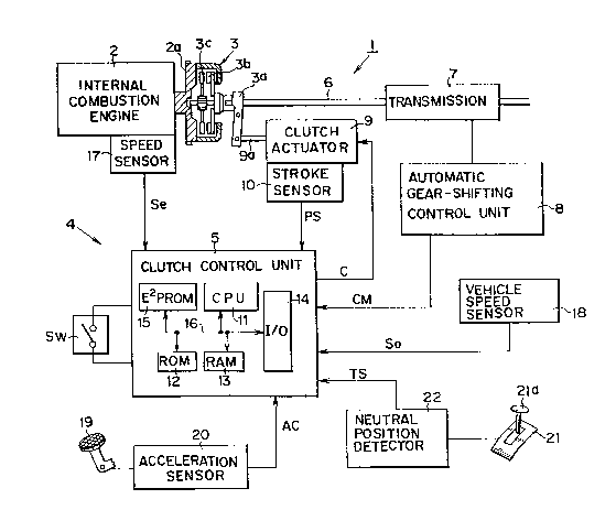
Fig. 1 schematically shows an embodiment of a
vehicle transmission control system including a clutch
controlling system in which clu-tch data concerning a friction
type clutch is corrected according to the method of the
present invention. Reference numeral 1 generally designates a
vehicle transmission control system for a vehicle (not shown)
powered by an internal combustion engine 2, and a friction
clutch 3 is mounted on an engine flywheel 2a. The friction
clutch 3 is à well-known dry-type single-disc clutch having a
clutch release lever 3a, a pressure plate 3b and a clutch disc
3c, and is controlled by a clutch control system 4 including a
clutch control unit 5. The clutch 3 is connected by a
connecting rod 6 with a gear transmission 7, which is
associated with an automatic gear-shifting control unit 8 to
form a conventional automatic gear-shifting control system.
In order to control the engaging/disengaging
(ON/OFF) operation of the clutch 3 in response to an electric
signal, the clutch control system 4 has a clutch actuator 9
having a piston rod 9a connected with the clutch release lever
3a, and the clutch actuator 9 is responsive to a control
signal C generated by the clutch control unit 5 to control the
position of the pressure plate 3b, whereby the amount of
operation of the clutch 3 can be controlled.
For detecting how the clutch 3 is being operated at
each moment, in other words, for detecting the operation
. ~ , ' , '
' ' ~
., .
condition of the clutch 3, a stroke sensor 10 is coupled with
the clutch actuator 9 to detect the operation position of the
release lever 3a of the clutch 3 and a position signal PS
indicating the operation position of the release lever 3a is
produced by the stroke sensor 10. Since the position of the
pressure plate 3b, on which the operation condition of the
clutch 3 depends, has a predetermined relation with the
operation position of the release lever 3a, it follows that
the position signal PS from the stroke sensor 10 indicates the
position P of the pressure plate 3b.
The position signal PS is supplied to the clutch
control unit 5 which includes a central processing unit (CPU)
11, read-only memory (ROM) 12, random access memory (RAM) 13,
I/O interface 14 and an electrically erasable programmable
read-only memory (EEPROM) 15, which are interconnected by a
bus 16 to form a conventional microcomputer system.
Reference symbol SW designates a power switch of the
vehicle transmission control system 1 shown in Fig. 1 and the
power is applied to the vehicle transmission control system 1
when the switch SW is turned on.
Associated with the internal combustion engine 2 is
a speed sensor 17, which is a sensor of well-known design for
detecting the input rotational speed N of the clutch 3 and
producing a first speed signal Se indicating this speed. A
vehicle speed sensor 18, which is a conventional sensor for
detecting the running speed of the vehicle, produces a second
speed signal So showing the vehicle running speed. The first
~ .
~J ~
and second speed signals Se and So are supplied to the clutch
control unit 5 to which an acceleration signal AC indicating
the amount of operation of an accelerator pedal 20 is further
applied from an acceleration sensor 20 for detectin~ the
amount of operation of the accelerator pedal 19.
Data corresponding to the designed-in relationship
between the position P of the pressure plate 3b indicated by
the position signal PS and the operation condition of the
clutch 3 is stored in the ROM 12 as initlal clutch data. The
initial clutch data includes first data showing an OFF
position P1 of the clutch 3 at which the pressure plate 3b is
ma~imally apart from the clutch disc 3c and the clutch 3 is in
its fully disengaged state, second data showing a meet
position P2 (> P1) of the clutch 3 which is a position of the
pressure plate 3b at which the input shaft of the transmission
7 begins to rotate owing to the fact that the operation of the
clutch 3 changes from its disconnected state to its semi-
engaged state to cause torque transmitting operation, third
data showing a finish position P3 (> P2) of the clutch 3 which
is a boundary position between the semi-engaged state and the
engaged state of the clutch 3, and fourth data showing an ON
position P4 ( > P3) at which the pressure plate 3b maximally
pushes the clutch disc 3c to obtain the fully engaged state of
the clutch 3.
Fig. 2 shows the relationship based on the initial
clutch d=ta~between the position P of the pressure plate 3b of
the clutch 3 and the torque transmitted therethrough.
The initial clutch data s-tored in the ROM lZ is
transferred to the RAM 13 in response to the supply of power
to the clutch control unit 5, and the initial clutch data is
stored in the RAM 13 as clutch data used for cantrolling the
clutch 3. The clutch control unit 5 is responsive to a
command signal CM from the automatic gear-shifting control
unit 8, and produces the control signal C for controlling the
clutch 3 with reference to the clutch data stored in the RAM
13 and the position signal PS so as to obtain the desired
operation condition of the clutch 3 in accordance with the
command signal CM. In this embodiment, the command signal CM
is for commanding the start time of the operation for
engaging/disengaging the clutch 3 in order to carry out
automatic gear-shifting operation of the transmission 7.
lS Since the relationship between the position P of the
pressure plate 3b indicated by the position signal PS and the
operation condition of the clutch 3 (the torque transmitted
through the clutch 3) varies due to, for example, wear of
various portions of the clutch 3 with the passage of time, for
assuring precise control of the clutch 3, it is necessary to
correct the clutch data at appropriate time intervals. For
this purpose, the clutch control system 4 shown in Fig. 1 has
a neutral position detector 22 coupled with a gear selector 21
having a selecting lever 21a, and a learning timing signal TS
is generated by the neutral position detector 20 each time the
selecting lever 21a is positioned at its neutral (N) position.
The learning timing signal TS is applied to the clutch con-trol
g _
, ~
~ h~
unit S and a predetermined learning operation for detecting
the actual meet position is carried ou-t for predetermined
conditions by the clutch control unit 5 to obtain learned data
Dn showing the resulting learned meet position.
The last meet position data Ds used for the
preceding control operation is stored in the EEPROM 15 and the
up-dated meet positi.on data is determined on the basis of the
data Ds by taking into account the learned data Dn obtained in
accordance with programs stored in the ROM 12 in advance. The
updating operation of the meet position data Ds is carried out
by a learning operation in accordance with a correction
program for updating the meet position data, which is stored
ln the ROM 12 in advance and is executed in the microcomputer
in the clutch control unit 5.
Description will be now given to the processing
operation executed in the clutch control unit 5, in which the
meet position data is up-dated by the use of the learned data
representing the actual meet position of the clutch 3 by the
learning operation in accordance with the present invention,
with reference to Figs 3 to 5.
Fig. 3 is the flowchart showing a first processing
program 30 used for setting the data stored in the EEPROM 15
to the RAM 13, Fig. 4 i9 the flowchart showing a second
processing program 40 used for storing the learned data in the
RAM 13 lnto the EEPROM 15 at the time the system control
operation is terminated, and Fig. 5 is the flowchart showing a
; correction program 50 used for correcting or updating the meet
- 10 ~ '
--~ 4~ ~3 ~ 3
position data by the use of the learned data showing the
actual meet position of -the clutch 3.
When the power is supplied to the vehicle
transmission control system 1 including the clutch con-trol
system 4 upon the closing of the switch SW, the execution of
the first processing program 30 starts with system
initialization in step 31. Then, the operation moves to step
32, in which the last meet position data Ds used for the
control operation carried out before the switch SW was closed
is read out from the EEPROM 15 and the last meet position data
Ds is set at a designated address of the RAM 13. Thus, the
system is made ready for updating the meet position data by
the use of the learned data, and the execution of the first
processing program 30 is completed.
The correction program 50 is adapted to be executed
each time the learning timing signal TS is applied to the
clutch control unit 5. After the start of the execution of
the processing program 50, the operation moves to step 51 in
which the learning operation for obtaining the current meet
position is carried out by producing the control signal C so
as to cause the clutch 3 to operate and then detecting the
current meet position of the clutch 3 during its operation.
Thus, the current meet position is determined in a
conventional manner on the basis of the first speed signal Se
and the position signal PS, which are supplied to the clutch
control unit 5 at that time. As a result learned data Dn
representing the current meet position is obtained. The
. ~
h)~3~Yl~,,,L~
learned data Dn shows the actual position P2 at this time.
Then, the operation moves to step 52 in which
discrimination is made as to whether or not a flag F is
cleared. Since the flag F is cleared upon the power-on
operation ~or the vehicle transmission control system 1, the
determination in step 52 will be YES if the discrimination in
step 52 is the first execution af~er power-on.
The operation moves to step 53 when the
determination in step 52 is ~ES, and the flag F is set in step
53. In the subsequent step 54 the learned data Dn obtained in
step 51 is compared in magnitude with the meet position data
Ds, which shows the meet position used for controlling the
clutch operation in the preceding control operation and is set
into the RAM 13 in step 32 of the first processing program 30.
When the difference between Dn and Ds is greater
than a prescribed value K, the operation moves to step 55, in
which the learned data Dn obtained during the execution of
this program cycle is stored in the RAM 13 as up-dated meet
position data Ds instead of the last meet position data Ds
obtained in the preceding processing operation. On the other
hand, when.the difference between Dn and Ds is equal to or
smaller than K, the determinati.on in step 54 becomes NO and
the operation moves to step 56, in which the up-dated meet
position data Ds to be stored in the RAM.13 in place of the
last meet position data Ds is calculated in accordance with
the following formula:
Ds~ Z ~ Z) ~ Dn ... (1
- :
Wherein Z is smaller than 1.
The resulting meet position data calculated in
accordance with the formula (1) is stored in the RAM 13 as the
up-dated meet position data Ds. Thus, the execution of the
correction program 50 is completed at this time.
As will be understood from the foregoing
description, when the flag ~' has been once set in step 53, the
step 56 is always executed for updating the meet position data
Ds in accordance with the formula (1) in the subsequent
program cycles, that is, in each program cycle other than the
first program cycle.
The execution of the second processing program 40
starts in response to the turning off of the switch SW and the
operation moves to step 41 in which a processing operation for
tèrminating the control operation is executed. Then, in step
42 the up-dated meet position data Ds stored in the RAM 13 is
transferred into the EEPROM 15 to save the same. After this,
the self-holding circuit (not shown) is turned off in step 43,
whereafter it stands by for the next turn-on of the switch SW.
According to the arrangement described above, in the
case of the first learning operation after turn-on of the
switch SW, the last meet position data Ds used in the
preceding control operation is compared with the learned data
Dn obtained in the first learning operation and if the
25 difference therebetween is grater than a prescribed value, the ?
learned data ?Dn is sotred, without modification, as the up-
dated meet position data Ds in the RAM 13. Consequently, in
- 13 -
* ~
the case where the meet position data has changed yreatly due
to the adjustment or replacement of the link mechanism in the
actuating system of the clutch 3, the replacement of a sensor
or the like, up-dated meet position data properly representing
the current meet position of the clutch is detected by the
learning operation in the subsequent control operation of the
vehicle transmission control system 1, and the meet position
data Ds is changed to the correct meet position data obtained
in the first learning operation after turn-on of the switch
SW. On the other hand, regarding changes in the meet position
data occurring during the control operation after the first
lea.rning operation, the meet position data is not changed by a
large degree but is changed taking account of the meet
position data Ds used in the preceding control operation in
lS the conventional manner according to the formula (1). Thus
stable clutch control operation can be realized even when a
faulty learning operation occurs because the meet position
data is not changed directly on the basis of the result of the
learning operation for detecting the meet position of the
clutch.
In the foregoing cases, the value of Z can be
determined experimentally or on the basis of an appropriate
standard.
- 14 -
":