Language selection

Search

Patent 2044277 Summary

Third-party information liability

Some of the information on this Web page has been provided by external sources. The Government of Canada is not responsible for the accuracy, reliability or currency of the information supplied by external sources. Users wishing to rely upon this information should consult directly with the source of the information. Content provided by external sources is not subject to official languages, privacy and accessibility requirements.

Claims and Abstract availability

Any discrepancies in the text and image of the Claims and Abstract are due to differing posting times. Text of the Claims and Abstract are posted:

  • At the time the application is open to public inspection;
  • At the time of issue of the patent (grant).
(12) Patent: (11) CA 2044277
(54) English Title: THERMAL INTER-COOLER
(54) French Title: REFROIDISSEUR INTERMEDIAIRE
Status: Expired and beyond the Period of Reversal
Bibliographic Data
(51) International Patent Classification (IPC):
  • F25B 40/02 (2006.01)
  • F25B 40/00 (2006.01)
(72) Inventors :
  • NIVENS, JERRY W. (United States of America)
(73) Owners :
  • JOHN N. HARBINSON LTD.
(71) Applicants :
  • JOHN N. HARBINSON LTD. (Canada)
(74) Agent: KIRBY EADES GALE BAKER
(74) Associate agent:
(45) Issued: 1998-08-11
(86) PCT Filing Date: 1990-01-23
(87) Open to Public Inspection: 1990-08-04
Examination requested: 1992-05-12
Availability of licence: N/A
Dedicated to the Public: N/A
(25) Language of filing: English

Patent Cooperation Treaty (PCT): Yes
(86) PCT Filing Number: PCT/US1990/000324
(87) International Publication Number: US1990000324
(85) National Entry: 1991-06-18

(30) Application Priority Data:
Application No. Country/Territory Date
306,330 (United States of America) 1989-02-03

Abstracts

English Abstract


A non-restrictive, constant pressure refrigerant
recycling and cooling unit (2) that interrupts the normal
refrigerant cycle to permit a lower temperature liquid to enter
the expansion device (5), and thus provide a lower temperature,
and therefore a lower pressure gas for delivery to the inlet side
(8) of the compressor (9), which acts to reduce the energy
requirement and cost to operate the compressor. This reduction
in pressure and temperature also results in lower operating costs
and lower maintenance costs and utilizes less refrigerant
quantity requirements. A key factor in attaining the above
advantages is the construction of the thermal inter-cooler that
is so made that no restrictions are specifically inserted in the
inter-cooler system, and that direct physical contact exists
between the metal compressor inlet suction line (22) and the
metal (Cu) refrigerant hot line (24) for optimum heat transfer,
and pressure reduction throughout the system.


French Abstract

Appareil à passage intégral fonctionnant à température constante pour assurer la recirculation et le refroidissement (2) d'un liquide frigorigène en interrompant le cycle normal du frigorigène pour permettre l'admission d'un liquide à plus basse température à l'intérieur du détendeur (5), ce qui permet d'alimenter le compresseur (9) d'un gaz à plus basse température et à plus basse pression, et qui contribue à diminuer les besoins et les coûts énergétiques associés au fonctionnement du compresseur. Cette réduction de la pression et de la température entraîne également une diminution des coûts d'exploitation et d'entretien, et se traduit par l'utilisation de moins grandes quantités de frigorigène. La construction d'un refroidisseur intermédiaire est un facteur-clé pour atteindre les objectifs mentionnés ci-dessus; celui-ci doit être construit de manière à ne pas entraver la libre circulation du liquide, tout en préservant le contact physique direct entre la conduite d'aspiration du compresseur (22) et la canalisation de frigorigène en cuivre (24), afin d'assurer un transfert thermique optimal et une réduction de la pression à l'intérieur de l'ensemble du système.

Claims

Note: Claims are shown in the official language in which they were submitted.


-7-
What is Claimed is:
1. In a refrigeration system complete with
compressor, condenser, expansion device, and evaporator,
employing less than a full amount of refrigerant, the
improvement comprising:
a) the addition of a thermal inter-cooler, between
said condenser and said expansion device, and between said
evaporator and said compressor, having an outer shell;
b) said inter-cooler and associated connections
having no inserted restrictions to fluid flow therethrough;
c) a cold suction line running from an output side of
said evaporator to an input side of said compressor and
carrying cooler than ambient refrigerant gas;
d) said suction line passing axially through said
thermal inter-cooler;
e) a hot refrigerant gas line running from an output
side of said compressor to an input side of said condenser;
f) a hot refrigerant gas and liquid line running from
an output side of said condenser to an input side of said
thermal inter-cooler and overlaying said suction line in an
axial direction within said outer shell, and having a distal
end; and
g) an exit opening at the distal end of said gas and
liquid line, whereby the gas and liquid fluids spray into
the interior of said shell and collect in the bottom of said
shell as liquid only and at a substantially reduced
temperature and pressure prior to exiting to said expansion
device thereby reducing the load and power requirements on
said compressor and system.

-8-
2. In a refrigeration system complete with
compressor, condenser, expansion device, and evaporator;
employing less than a full amount of refrigerant, the
improvement comprising:
a) the addition of a thermal inter-cooler, between
said condenser and said expansion device, and between said
evaporator and said compressor having an outer shell;
b) said inter-cooler and associated connections
having no added restrictions to fluid flow therethrough;
c) a cold suction line running from an output side of
said evaporator to an input side of said compressor and
carrying cooler than ambient refrigerant gas;
d) said suction line passing longitudinally through
said thermal inter-cooler;
e) a hot refrigerant gas line running from an output
side of said compressor to an input side of said condenser;
f) a hot refrigerant gas and liquid line running from
an output side of said condenser to an input side of said
thermal inter-cooler and overlaying said suction line in a
longitudinal direction within said outer shell, and having
a distal end; and
g) an exit opening at the distal end of said gas and
liquid line, whereby the gas and liquid fluids spray into
the interior of said shell and collect in the bottom of said
shell as liquid only and at a substantially reduced
temperature and pressure prior to exiting to said expansion
device thereby reducing the load and power throughout the
refrigeration system.

-9-
3. A thermal inter-cooler as in claim 1, having an
internally located concentric axial pipe extending therein,
wherein said gas and liquid line expands into the annular
space between said axial pipe and said suction line, whereby
the fluid in said gas and liquid line sprays into the
interior of said shell, and the gas content therein
condenses and deposits in the bottom of said shell as a
portion of the liquid seal that exits to said expansion
device.
4. A thermal inter-cooler as in claim 1, wherein said
hot refrigerant gas and liquid line is circular in
configuration as it enters said shell, and is oval shaped to
snugly engage a larger portion of the circumference of said
suction line for a substantial distance prior to opening
into the interior of said shell.
5. A thermal inter-cooler as in claim 2, wherein said
axial pipe terminates prior to traversing the full interior
length of said shell.
6. A thermal inter-cooler as in claim 2, wherein said
liquid seal extends above the centerline of said shell.
7. A thermal inter-cooler as in claim 6, wherein said
shell is oriented in a generally horizontal position when
installed in said refrigeration system.

-10-
8. A thermal inter-cooler as in claim 4, wherein the
longest dimension of said oval shaped line cross-section is
at least as great as the diameter of said suction line.
9. A thermal inter-cooler as in claim 8, wherein said
oval shaped line is made of copper.
10. A thermal inter-cooler as in claim 3, wherein
copper is at least the predominant material of said thermal
intercooler.

-11-
11. In a refrigeration system, including at least a
compressor, condenser, expansion device, and evaporator, the
improvement comprising:
a thermal inter-cooler, having an outer shell;
said inter-cooler and associated connections having no
inserted restrictions to fluid flow therethrough;
a cold line extending axially through said
inter-cooler, for carrying cooler than ambient refrigerant
received from said evaporator;
a hot refrigerant line running from an input side of
said inter-cooler and at least partially overlaying said
cold line, within said outer shell, for carrying warmer than
ambient refrigerant received from said condenser, and having
a distal end;
an exit opening in the distal end of said hot
refrigerant line, for discharging refrigerant from the hot
refrigerant line into the outer shell, at a temperature and
pressure substantially reduced by refrigerant carried by the
cold line, thereby reducing load and power requirements of
the refrigeration system compressor; and
a discharge opening in the outer shell for discharging
liquid refrigerant from within the outer shell to the
refrigeration system at a position upstream of the expansion
device.
12. A refrigeration system as in claim 11, further
comprising:

-12-
condensing means within the interior of said outer
shell of said inter-cooler, for condensing refrigerant gas
contained by the shell, thereby causing condensate to
collect in the bottom of said shell as a liquid, whereupon
it is delivered to the refrigeration system at a position
upstream of the expansion device.
13. A refrigeration system as in claim 11, further
comprising:
condensing means within said outer shell of said
inter-cooler, for condensing refrigerant gas discharged from the
hot refrigerant line, thereby causing condensate to collect
at the bottom of said shell; and
wherein said discharge opening in said outer shell is
positioned below the expected level of liquid refrigerant
and condensate collected within the outer shell, to provide
a liquid seal against the discharge of gaseous refrigerant
from the inter-cooler to the refrigeration system.

-13-
14. In a refrigeration system, complete with
compressor, condenser, expansion device, and evaporator,
employing an amount of refrigerant, including hot and cold
lines, the improvement comprising:
the addition of a thermal inter-cooler having an outer
shell, intercepting said hot line;
one of said cold lines, using a cooling medium, running
from an output side of said evaporator through said
inter-cooler, and to an input side of said compressor, and
carrying cooler than ambient refrigerant;
said cold line passing axially through said thermal
inter-cooler; and
a hot line running from the condenser into the
inter-cooler and overlaying and partially surrounding said cold
line in an axial direction within said outer shell, and
having a distal end; and
a discharge opening through the housing, for removing
from the housing liquid refrigerant discharged from the hot
line.
15. A thermal inter-cooler for use in a refrigeration
system to increase efficiency of the system, comprising:
an elongated housing having first and second ends;
a cool refrigerant line passing axially through the
housing, without restriction, for carrying cooler than
ambient refrigerant from the first to the second end of the
housing;

-14-
a warm refrigerant line extending into the housing and
at least partially surrounding the cool refrigerant line,
for receiving warmer than ambient refrigerant from the
refrigeration system, for cooling the refrigerant, and for
discharging the refrigerant into the housing;
the warm refrigerant line having an unrestricted
opening positioned within the housing, for allowing
substantially unrestricted discharge of refrigerant from the
line, into the housing; and
a discharge opening through the housing, for removing
from the housing liquid refrigerant discharged from the warm
refrigerant line.
16. A thermal inter-cooler as in claim 15, wherein
said warm refrigerant line attaches and conforms in part to
the shape of said cool refrigerant line.
17. A thermal inter-cooler as in claim 15, having no
restrictive functional devices in any external connecting
lines thereto.
18. A thermal inter-cooler as in claim 15, functioning
as a means to allow an undercharged refrigerant system to
operate in a normal manner, without adverse side effects.

Description

Note: Descriptions are shown in the official language in which they were submitted.


2 7 7
Thermal Inter-Cooler
Field of the Invention
This invention relates to a thermal inter-cooler for
use in any type of refrigeration system that employs a liquid and
gas refrigerant. In most instances, similar systems would employ
a compressor to compress and pressurize a refrigerant gas, such
as Freon (trade mark), which would then be condensed into a
partial liquid and gaseous state, and be directed into a housing
through a series of restricted nozzles, where it would expand and
cool and experience a pressure drop and then recondense as a
somewhat denser liquid in the bottom of the housing before
exiting through the outlet on its way to an expansion valve ahead
of the evaporator, whereat the refrigerant enters the expansion
device as a somewhat cooler liquid, but also as an imperfect
liquid and gas mixture in prior systems.
Brief Description of the Prior Art
Many prior attempts have been made to create an
efficient and economical subcooler for use in refrigeration
systems, but each has included certain drawbacks and limitations
in their performance, such as intentionally inserted
restrictions, i.e., nozzles that restrict and interrupt the
smooth flow of refrigerant and create a larger than necessary
back pressure. The present invention includes improved
structural and conceptual parts that permit its performance and
results to approach the optimum for the purpose intended.
In patent No. 4,207,739, to LeVigne, entitled Thermal
Economized Refrigeration System, employs a series of nozzles to
deliberately maintain a pressure drop in his refrigerant line,
and his condenser and economizer each require a separate source
of cool fluid to circulate therethrough.
Patent No. 4,633,726, to Barron, entitled Refrigeration
Apparatus also requires the use of a plurality of restrictive
nozzles in his subcooler, and further requires that his subcooler
be located in the cold air stream from the evaporator.

204~277
The Kann patent No. 4,773,234, also includes flow
restricting nozzles to intentionally produce a pressure drop
between the subcooler and th~e receiver.
In contrast to these and other prior art patents, this
Applicant does not intentionally insert any restrictions into his
refrigerant flow system, but permits his direct metal to metal
contact between the refrigerant line and a cooler line in the
system to provide temperature reduction required for his
efficient operation.
Summary of the Invention
An object of this invention is to provide a structure
for a refrigeration system thermal "intermediate" cooler that
does not include any imposed restrictions in the refrigerant path
through the system that would physically cause a pressure drop
across this unit.
Another object is to provide a heat transfer path for
the refrigerant to traverse that provides a substantial length
and area of metal to metal contact between the line carrying the
hot refrigerant liquid and the line carrying the cool expanded
refrigerant gas.
A further object is to provide a dual stage cooler for
the hot refrigerant gas without the inclusion of any inserted
physical restrictions in the refrigerant line.
Yet another object of this invention is to provide a
device of this type comprising a cooling shell into which the
liquid and gas refrigerant expands and permits liquid only to
collect in the lower portion of the shell and be withdrawn to
feed into an expansion device in a condition known in the trade
as a "liquid seal".
And another object is to provide a device of the
previous object in which the inter-cooler will perform without
appreciable drop in performance even when the shell is filled
with liquid or when it is three-fourth empty of liquid.

20 44 277
According to one aspect of the present invention there
is provided in a refrigeration system complete with compressor,
condenser, expansion device, and evaporator, employing less than
a full amount of refrigerant, the improvement comprising: a) the
addition of a thermal inter-cooler, between said condenser and
said expansion device, and between said evaporator and said
compressor, having an outer shell; b) said inter-cooler and
associated connections having no inserted restrictions to fluid
flow therethrough; c) a cold suction line running from an output
side of said evaporator to an input side of said compressor and
carrying cooler than ambient refrigerant gas; d) said suction
line passing axially through said thermal inter-cooler; e) a hot
refrigerant gas line running from an output side of said
compressor to an input side of said condenser; f) a hot
refrigerant gas and liquid line running from an output side of
said condenser to an input side of said thermal inter-cooler and
overlaying said suction line in an axial direction within said
outer shell, and having a distal end; and g) an exit opening at
the distal end of said gas and liquid line, whereby the gas and
liquid fluids spray into the interior of said shell and collect
in the bottom of said shell as liquid only and at a substantially
reduced temperature and pressure prior to exiting to said
expansion device thereby reducing the load and power requirements
on said compressor and system.
According to another aspect of the present invention
there is provided in a refrigeration system complete with
compressor, condenser, expansion device, and evaporator,
employing less than a full amount of refrigerant, the improvement
comprising: a) the addition of a thermal inter-cooler, between
said condenser and said expansion device, and between said
evaporator and said compressor having an outer shell; b) said
inter-cooler and associated connections having no added
restrictions to fluid flow therethrough; c) a cold suction line
running from an output side of said evaporator to an input side
of said compressor and carrying cooler than ambient refrigerant
gas; d) said suction line passing longitudinally through said
thermal inter-cooler; e) a hot refrigerant gas line running from
B-
J

2 Q 4 4 2 7 7
an output side of said compressor to an input side of said
condenser; f) a hot refrigerant gas and liquid line running from
an output side of said condenser to an input side of said thermal
inter-cooler and overlaying said suction line in a longitudinal
direction within said outer shell, and having a distal end; and
g) an exit opening at the distal end of said gas and liquid line,
whereby the gas and liquid fluids spray into the interior of said
shell and collect in the bottom of said shell as liquid only and
at a substantially reduced temperature and pressure prior to
exiting to said expansion device thereby reducing the load and
power throughout the refrigeration system.
According to yet another aspect of the present
invention there is provided in a refrigeration system, including
at least a compressor, condenser, expansion device, and
evaporator, the improvement comprising: a thermal inter-cooler,
having an outer shell; said inter-cooler and associated
connections having no inserted restrictions to fluid flow
therethrough; a cold line extending axially through said inter-
cooler, for carrying cooler than ambient refrigerant received
from said evaporator; a hot refrigerant line running from an
input side of said inter-cooler and at least partially overlaying
said cold line, within said outer shell, for carrying warmer than
ambient refrigerant received from said condenser, and having a
distal end; an exit opening in the distal end of said hot
refrigerant line, for discharging refrigerant from the hot
refrigerant line into the outer shell, at a temperature and
pressure substantially reduced by refrigerant carried by the cold
line, thereby reducing load and power requirements of the
refrigeration system compressor; and a discharge opening in the
outer shell for discharging liquid refrigerant from within the
outer shell to the refrigeration system at a position upstream
of the expansion device.
2b
B

2 Q ~ ~ ~ 7 1
JescriPtion of the Drawinqs
FIG. 1 is a schematic diagram of a~typical refrigerant
system which employs the thermal inter-cooler of this invention;
FIG. 2 is a partially sectioned view of one embodiment
of the inter-cooler of this invention;
FIG. 3 is a cross-section taken along the lines 3-3 of
Fig. 2;
FIG. 4 is a cross-sectional view of a second embodiment
of this invention;
FIG. 5 is a cross-section taken along the lines 5-5 of
FIG. 4;
FIG. 6 is a cross-sectional view of a third embodiment
of this invention;
FIG. 7 is a cross-section taken along the lines 7-7 of
Fig. 6;
FIG. 8 is a partially cross-sectioned view of a fourth
embodiment of this invention.
Description of the Preferred Embodiments
Referring now more particularly to the characters of
reference of the drawing, it will be observed that Fig.
schematically depicts a refrigeration system 1 including the
thermal inter-cooler 2 of this invention interposed between the
condenser 3, the optional receiver 4, and the expansion device
5 at the evaporator 6, and wherein the outlet line 7 from the
evaporator passes through the cooler 2 and thence to the inlet
or suction side 8 of the compressor 9. The low pressure,low
temperature refrigerant gas from the evaporator 6 (through the
inter-cooler 2) enters the compressor at 8 in a relatively low
temperature, low pressure state, and then exits the compressor
at line 10 in a relatively hotter temperature and relatively
higher pressure when it enters the condenser 3 at inlet 11.
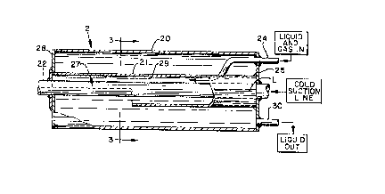
In Fig. 2, the first embodiment of the thermal conden-
ser 2 is seen to comprise an outer shell 20 of a good thermal
conducting metal such as aluminum, copper, steel, or other known
materials. The large central axial pipe or tube 21 is of a
smaller diameter than the shell 20, and may be concentrically

~n44~77
installed therein. Another good heat conducting material tube
22 extends axially and also concentrically through the shell 20
and pipe 21 and comprises the outlet line 7 that traverses from
the evaporator 6 to compressor inlet 8. The inlet line 24 from
the condenser/receiver enters through the right end plate 25 of
cooler 2, and engages the top side of pipe 21 in such a manner
that fluid travelling through the lines 24 expands into the
annular space 29 between pipe 21 and tube 22 until it exits at
the cutaway portion 27 before reaching left end plate 28. Upon
exiting from the annulus 29, any entrapped gas condenses into
liquid and combines with the liquid in the line and fills the
lower portion of shell 20 and exits therefrom through outlet 30
as a "liquid seal" L, without entrapped gas. This total
condensation is due in part to the expansion of the mixture out
through the cutaway 27, and in part due to the close contact with
the cold suction line 22, and in part to contact of the fluid
with the inner wall of the shell 20, which is installed in a cold
ambient location.
Liquid refrigerant proceeds from outlet 30 through line
31 to expansion device 5, which is normally a valve, and through
line 32 to evaporator 6, wherein the liquid is converted into a
lower temperature and lower pressure gas that passes through
cooler 2 via tube 22 on its way to the suction side of compressor
9 via its intake opening 8. The utilization by the compressor
8 of a lower than the normal intake pressure (and temperature)
will result in a lower power requirement by the compressor, which
translates into greater efficiency and lower cost, and this
feature has been confirmed by tests and charts of "before" and
"after" installations.
In Fig. 3, the liquid L is shown to have a liquid level
slightly above the centerline of the concentric structures. It
has been found, however, that his inter-cooler 2 will function
very satisfactorily when the liquid level is in the range from
100% full to 75% empty. The dimensional difference between the
inner diameter of pipe 21 and the outer diameter of tube 22, is
of the order of one-eighth of an inch in one preferred embodi-
ment, so that inlet fluid in the annular space 29 is in a very
.

204~277
efficient heat transferring relationship with cold tube 22, pipe
21 and the cooler liquid L.
Fig. 4 represents a preferred embodiment of this
thermal inter-cooler 2A, wherein the inlet line 24 converts into
5 an expanded generally oval shaped tube 41, with open end 47 to
permit exit of the entering gas and liquid to spray into the open
area 44 of shell 40, whereupon and gas in the entering mixture
condenses upon contact with the cold tube 22, the cool inner wall
of shell 40, and end walls 48 and 25, or the cooler liquid L, so
that the exiting fluid at 30 will be a "liquid seal", identified
here as L. The long extended metal to metal contact between tube
section 41 and the cold center tube 22 may best be seen in Fig.
5. This intimate continuous contact for a considerable length
is a key reason for the success of this particular embodiment
15 over the prior art. A non-analogous comparison of this phenome-
non, is that the heat in the hot refrigerant tube 24 appears to
be magnetically attracted into the cold suction tube 22. End
plate 48 of this embodiment snugly surrounds the exiting cold
tube 22, as contrasted to the end plate 28 of embodiment 2.
Embodiment 2B of Fig. 6 differs from the embodiments
of Figs 2 and 4, in that it provides for a much longer travel
path for the incoming fluid mixture via line 24 that is spirally
wound at 51 around the center cold tube 22, before the fluid
exits at 57 as a mixture of gas and liquid into the large open
interior enclosed by shell 40A and end plates 48 and 45. The gas
content of the exiting fluid immediately condenses on contact
with the inner wall of shell 40A, end plates 45 or 48, the cold
center tube 22, or the cooler liquid L in the lower area of shell
40A. The liquid seal L exiting at 30, proceeds through line 31
30 to expansion device 5 to rejoin the total refrigeration system
1.
Fig. 7 is an axial section showing the interior ofembodiment 2B of Fig. 6. The spiral configuration 51 of fluid
inlet tube 24 entering into the shell 40A is determined by
35 weighing the factors of providing the maximum area of heat
transfer contact against the increased friction imposed in the
travel path of the incoming fluid through a long and tortuous

2044277
route to reach exit 57. This, of course, is one of the advantag-
es of the embodiment 2A, which utilizes a~ long but straight
travel path to its exit 47.
In Fig. 8, the details of embodiment 20 may be observed
to include an outer shell 50 having end plates 48 and 55, which
permit the passage therethrough of center cold tube 22. End
plate 55, additionally permits the entrance and passage of pipe
54 concentrically of both shell 50 and center tube 22. End plate
55 is attached by welding or otherwise to extension 53 and end
plate 52 is likewise attached to tube 22 to provide an enclosure
seal for fluid entering through tube 24. The incoming fluid
fills the annular region 59 of the cantilever suspended pipe 54,
and proceeds to the open exit end 56, whereupon it expands and
any gas therein condenses and fills the lower part of shell 50
with liquid seal (not shown in this view), as a portion of said
liquid seal exits through outlet tube 30 back into the refrigera-
tion cycle.
It should be understood that this invention is not
limited to the described embodiments disclosed herein, except as
their structure and function fall within the scope of the
appended claims.

Representative Drawing
A single figure which represents the drawing illustrating the invention.
Administrative Status

2024-08-01:As part of the Next Generation Patents (NGP) transition, the Canadian Patents Database (CPD) now contains a more detailed Event History, which replicates the Event Log of our new back-office solution.

Please note that "Inactive:" events refers to events no longer in use in our new back-office solution.

For a clearer understanding of the status of the application/patent presented on this page, the site Disclaimer , as well as the definitions for Patent , Event History , Maintenance Fee  and Payment History  should be consulted.

Event History

Description Date
Inactive: IPC from MCD 2006-03-11
Time Limit for Reversal Expired 2006-01-23
Letter Sent 2005-01-24
Inactive: Office letter 2001-11-01
Letter Sent 2001-11-01
Inactive: Multiple transfers 2001-09-21
Grant by Issuance 1998-08-11
Inactive: Final fee received 1998-04-20
Pre-grant 1998-04-20
Inactive: Multiple transfers 1998-01-07
Letter Sent 1997-11-07
Notice of Allowance is Issued 1997-11-07
Inactive: Status info is complete as of Log entry date 1997-11-03
Inactive: Application prosecuted on TS as of Log entry date 1997-11-03
Inactive: IPC removed 1997-10-02
Inactive: First IPC assigned 1997-10-02
Inactive: IPC assigned 1997-10-02
Inactive: Approved for allowance (AFA) 1997-10-01
All Requirements for Examination Determined Compliant 1992-05-12
Request for Examination Requirements Determined Compliant 1992-05-12
Application Published (Open to Public Inspection) 1990-08-04

Abandonment History

There is no abandonment history.

Maintenance Fee

The last payment was received on 1998-01-22

Note : If the full payment has not been received on or before the date indicated, a further fee may be required which may be one of the following

  • the reinstatement fee;
  • the late payment fee; or
  • additional fee to reverse deemed expiry.

Patent fees are adjusted on the 1st of January every year. The amounts above are the current amounts if received by December 31 of the current year.
Please refer to the CIPO Patent Fees web page to see all current fee amounts.

Fee History

Fee Type Anniversary Year Due Date Paid Date
Registration of a document 1996-07-18
MF (application, 8th anniv.) - small 08 1998-01-23 1998-01-22
Final fee - small 1998-04-20
Reversal of deemed expiry 2001-01-23 1999-01-21
MF (patent, 9th anniv.) - small 1999-01-25 1999-01-21
MF (patent, 10th anniv.) - small 2000-01-24 2000-01-13
Reversal of deemed expiry 2001-01-23 2000-01-13
Reversal of deemed expiry 2001-01-23 2001-01-23
MF (patent, 11th anniv.) - small 2001-01-23 2001-01-23
Registration of a document 2001-09-21
MF (patent, 12th anniv.) - small 2002-01-23 2001-10-25
MF (patent, 13th anniv.) - small 2003-01-23 2002-10-24
MF (patent, 14th anniv.) - small 2004-01-23 2003-12-29
Owners on Record

Note: Records showing the ownership history in alphabetical order.

Current Owners on Record
JOHN N. HARBINSON LTD.
Past Owners on Record
JERRY W. NIVENS
Past Owners that do not appear in the "Owners on Record" listing will appear in other documentation within the application.
Documents

To view selected files, please enter reCAPTCHA code :


To view images, click a link in the Document Description column. To download the documents, select one or more checkboxes in the first column and then click the "Download Selected in PDF format (Zip Archive)" or the "Download Selected as Single PDF" button.

List of published and non-published patent-specific documents on the CPD .

If you have any difficulty accessing content, you can call the Client Service Centre at 1-866-997-1936 or send them an e-mail at CIPO Client Service Centre.


Document
Description 
Date
(yyyy-mm-dd) 
Number of pages   Size of Image (KB) 
Description 1993-11-19 6 265
Abstract 1993-11-19 1 30
Claims 1993-11-19 5 216
Drawings 1993-11-19 2 83
Description 1997-09-07 8 393
Claims 1997-09-07 8 222
Representative drawing 1998-07-28 1 13
Commissioner's Notice - Application Found Allowable 1997-11-06 1 165
Courtesy - Certificate of registration (related document(s)) 1998-05-21 1 117
Courtesy - Certificate of registration (related document(s)) 2001-10-31 1 113
Maintenance Fee Notice 2005-03-20 1 172
Fees 2001-10-24 1 53
Fees 2003-12-28 1 50
Correspondence 1998-04-19 1 47
Correspondence 2001-10-31 1 13
Fees 2002-10-23 1 48
Fees 1999-01-20 1 51
Fees 2000-01-12 1 48
Fees 2001-01-22 1 52
Fees 1997-01-19 1 71
Fees 1993-01-24 1 30
Fees 1996-01-22 1 52
Fees 1995-01-22 1 55
Fees 1994-01-12 1 62
Fees 1992-01-21 1 21
Prosecution correspondence 1992-05-11 1 41
Examiner Requisition 1996-02-12 2 84
Prosecution correspondence 1996-08-12 1 49
Courtesy - Office Letter 1996-09-26 1 22
Courtesy - Office Letter 1996-07-17 1 34
PCT Correspondence 1996-07-12 2 79
Courtesy - Office Letter 1996-05-16 2 23
PCT Correspondence 1996-02-25 1 37
PCT Correspondence 1996-03-18 1 56
Courtesy - Office Letter 1996-12-11 1 23
Courtesy - Office Letter 1995-12-11 1 27
PCT Correspondence 1995-11-01 1 50
PCT Correspondence 1995-10-25 2 63
Courtesy - Office Letter 1992-06-11 1 36
PCT Correspondence 1996-03-18 1 62
International preliminary examination report 1991-06-17 30 1,148