Language selection

Search

Patent 2044443 Summary

Third-party information liability

Some of the information on this Web page has been provided by external sources. The Government of Canada is not responsible for the accuracy, reliability or currency of the information supplied by external sources. Users wishing to rely upon this information should consult directly with the source of the information. Content provided by external sources is not subject to official languages, privacy and accessibility requirements.

Claims and Abstract availability

Any discrepancies in the text and image of the Claims and Abstract are due to differing posting times. Text of the Claims and Abstract are posted:

  • At the time the application is open to public inspection;
  • At the time of issue of the patent (grant).
(12) Patent: (11) CA 2044443
(54) English Title: STRUCTURE OF STAPLER
(54) French Title: STRUCTURE D'AGRAFEUSE
Status: Expired and beyond the Period of Reversal
Bibliographic Data
(51) International Patent Classification (IPC):
  • B25C 5/02 (2006.01)
  • B25C 5/10 (2006.01)
  • B25C 5/16 (2006.01)
(72) Inventors :
  • SHIANG, LIOU HORNG (Taiwan, Province of China)
(73) Owners :
  • LIOU HORNG SHIANG
(71) Applicants :
(74) Agent: MARKS & CLERK
(74) Associate agent:
(45) Issued: 1995-07-04
(22) Filed Date: 1991-06-12
(41) Open to Public Inspection: 1992-12-13
Examination requested: 1992-01-02
Availability of licence: N/A
Dedicated to the Public: N/A
(25) Language of filing: English

Patent Cooperation Treaty (PCT): No

(30) Application Priority Data: None

Abstracts

English Abstract


A stapler for paper binding utilizes a
supporting means to firmly support staples so as to make
binding process easy and stable. A stapler of the present
invention includes a pressure plate spring received in a
pressure bar pivoted to a front-opened cartridge. The
pressure plate spring includes a front striking plate and a
front bumper to drive a staple for binding papers and to
confine such a staple from forward inclination. A
supporting wedge is received in the staple cartridge to
slide in the front and to firmly support the staple which
is driven downward for binding papers. Through the support
of the supporting wedge and the front bumper of the
striking plate of the pressure plate spring, staple is
protected to straightly strike downward for binding papers
efficiently.


Claims

Note: Claims are shown in the official language in which they were submitted.


-8-
THE EMBODIMENTS OF THE INVENTION IN WHICH AN EXCLUSIVE
PROPERTY OR PRIVILEGE IS CLAIMED ARE DEFINED AS FOLLOWS:
1. A stapler, including
a pressure bar;
a matrix base;
a front-opened staple cartridge for setting therein
of binding staples and comprising two side walls having their
front ends respectively bent inward to define therebetween an
opening, a bottom surface having mounted thereon a seat, two
guide rods respectively secured to said seat with two return
springs respectively mounted thereon:
a feed slide received in said staple cartridge and
connected to said seat by a spring;
a pressure plate spring received in said pressure
bar and comprising a front striking plate set in said opening
of said staple cartridge; and
a supporting wedge received in said staple
cartridge to slide on said two guide rods and comprising a
wedge-like front end, and being of such a size that when
placed in said staple cartridge, binding staples or said feed
slide can be mounted on a gap formed between said supporting
wedge and the two side walls of said staple cartridge;
wherein said pressure bar is pressed downward to
force said front striking plate of said pressure plate

-9-
spring to drive a staple received therein out of said
opening through papers fed therein, and simultaneously
to force said supporting wedge to gradually move backward,
such that such a staple is firmly confined by said front
striking plate, said supporting wedge, and said two side
walls of said staple cartridge to become stably driven
downward through the papers fed therein to efficiently
perform paper binding process.
2. A stapler according to claim 1, wherein said
opening which is defined between said two front ends of
said staple cartridge has a width equal to the interval
between the two vertical side rods of any staple to be
used.
3. A stapler according to claim 1 or 2, wherein
the front upper portions of the two side walls of said
staple cartridge are respectively turned inward to form two
projecting ends respectively connected together.
4. A stapler according to claim 3, wherein said
two projecting ends are connected through a tongue and a
retaining groove respectively made thereon.

- 10 -
5. A stapler according to claim 1 or 2, wherein
said staple cartridge comprises a setback notch at a front
bottom end in size equal to said opening, and an elongated
slide hole at the back of said notch; and said supporting
wedge comprises a bottom projection at the front bottom end
in thickness equal to the bottom surface of said staple
cartridge, and a positioning bolt on the bottom at the back
of said bottom projection permitting to slide in said
elongated slide hole.
6. A stapler according to claim 1, wherein said
striking plate of said pressure plate spring has secured
thereto a front bumper in size relatively smaller than said
opening of said staple cartridge, said front bumper having
its bottom end disposed at a level lower than said front
striking plate so as to define therewith a stepped bottom
surface.
7. A stapler according to claim 1 or 6, wherein
said pressure plate spring comprises an unitary push rod
extending downward and inward therefrom to constantly press
on said feed slide at a rear upper end so as to push said
feed slide forward during staple driving operation.

Description

Note: Descriptions are shown in the official language in which they were submitted.


20~443
-
STRIlCTURE C)F STAPLER
BACKGROUND OF THE INVENTION:
This invention relates to a stapler for dr1ving
staples through paper as for binding pamphlets.
In conventional staplers or stapling machines,
staples are received in a staple cartridge and bilaterally
supported by the bilateral side walls of such a staple
cartridge. If to bind up a big amount of papers at a time,
staples may be distorted during downward striking and
become unable to penetrate through the papers.
It is therefore, the main object of the present
invention to provide such a stapler which includes a front-
opened staple cartridge having received therein a
supporting wedge to slide in the front and to stably
suppoi-t ~tapies during aownward striking so as to make
binding process smooth and easy.
Another object of the present invention is to
provide such a stapler which includes a staple cartridge
having the two front upper portions of its two side walls
respectively turned inward to form two projecting ends
which are respectively connected together through a tongue
and a retaining groove respectively made thereon such that
$~

2~443
the two side walls thereof are firmly retained to
hilaterally support the staples received therein.
A yet further ohject of the present invention is
to provide such a stapler which includes a pressure plate
spring having an unitary push rod extending downward inward
therefrom to constantly press on the rear upper end of a
feed slide in a staple cartridge so as to push such a feed
slide forward during staple driving operation and to
prohibit staples from backward sliding.
Embodiments of the present invention will now be
described by way of example with reference to the annexed
drawings, in which:
BRIEF DESCRIPTION F THE DRAWINGS:
Fig. 1 is a perspective ~xploded view ~f a
stapler constructed according to the present invention;
Fig. 2 is a side sectional assembly view of the
stapler of Fig. 1; and
Fig. 3 is a sectional elevation of the stapler
of Fig. l illustrating the operation to drive a staple.
DETAI~ED DESCRIPTION F THE PREFERRED EMBODIMENTS:
Turning now to the annexed drawings in greater

- ~0~4~3
-
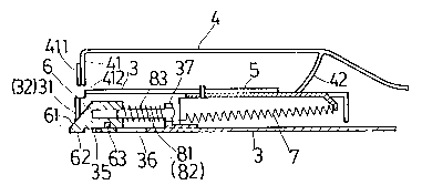
detail and first referring to Figs. 1 and 2, therein
illustrated is a stapler embodying the present invention
and generally comprised of a pressure bar 1, a matrix base
2, a staple cartridge 3, a pressure plate spring 4, a feed
5 slide 5, and a supporting wedge 6, wherein the pressure bar
1 and the matrix base 2 are similar to regular staplers and
not the scope of the present invention.
As illustrated, a staple cartridge 3 of the
present invention includes two front ends 31 and 32
respectively bent inward defining therebetween an openinq
33 in width equal to the interval between the two side rods
of any staple 9 to be used. The front upper portions of
the two side walls of said staple cartridge 3 are
respectively turned inward to form two projecting ends (34)
connected together through a tongue 342 and a retaining
groove 341 respectively made thereon. A setback notch 35
is made on the stable cartridge 3 at its front bottom end
in size equal to said opening 33. An elongated slide hole
36 is made at the back of the notch 35. A seat 37 is set
at the back apart from said elongated slide hole 36. A
spring 7 is connected to said seat 37 at the back side with
its opposite end secured to a feed slide 5. Two guide rods
81 and 82 are respectively secured to said seat 37 and
mounted with two return springs 83 respectively. Said
return springs 83 have their front ends respectively

2~44443
connected to a supporting wedge 6 which is movah].y mounted
on said guide rods 81 and 82. Said feed slide 5 has a
structure similar to a conventional stapler and is recelved
in said staple cartridge 3 at the back end.
A pressure plate spring 4 is set in a pressure
bar 1, which pressure plate spring 4 comprises a front
striking plate 41 having secured thereto a front bumper 411
in size relatively smaller than said opening 33. Said
front bumper 411 has its bottom end disposed at a level
lower than said front striking plate 41 to define therewith
a stepped bottom surface 412. An unitary push rod 42 is
extending downward and inward from said pressure plate
spring 4 at the rear end and made through punching and
bending process. During assembly, said striking plate 41
is inserted in said opening 33 and said push rod 42 is
pre~ed ~n ~aid f~ed slide 5 at the rear upper end.
Said supporting wedge 6 comprises a wedge-like
front end 61, two connecting holes 64 at its back side for
setting therein of said two guide rods 81 and 82, a bottom
projection 62 at its front bottom end in thickness equal
to the bottom surface of said staple cartridge 3, and a
po~itioning bolt 63 on its bottom at the back of said
bottom projection 62. Said supporting wedge 6 is properly

204444L3
.
made in such a size that when it is placed in said staple
cartridge 3, staples 9 or said feed slide 5 can be mounted
on the gap formed between said supporting wedge 6 and the
two side walls of said staple cartridge 3. During
assembly, said wedge-like front end 61 of said supporting
wedge 6 is disposed to protrude beyond said opening 33,
said bottom projection 62 is set in said setback notch 35,
and said positioning bolt 63 is set in said elongated slide
hole 36.
Operation of the present invention is outlined
hereinafter with reference made to the annexed drawings.
Pull open said pressure bar 1 and said feed slide 5 for
insertion of staples 9 in said staple cartridge 3. Then,
push said pressure bar 1 and said feed slide 5 back to
original position so as to push the inserted staples 9 to
the front end of said staple cartridge 3 in a ready
position for striking (as illustrated in Fig. 23. When
said pressure ~ar 1 is pressed down, the front striking
plate 41 of said pressure plate spring 4 is simultaneously
pushed to drive the front piece of the inserted staples 9
to move downward through said opening 33. During downward
striking, the wedge-like front end 61 is forced by the
upper cross rod of the staple, which is driven to move
downward, to gradually retreat along said guide rods 81 and
82 so that staple can be smoothly driven out of said staple

- 204~443
cartridge 3 for binding. As illustrated in Fig. 3, a
staple 9 i~ driven to strike downward. During downward
stroke, the front side and the upper side of the upper
cross rod of such a staple which is driven downward are
stably confined by said front striking plate 41 and said
front bumper 411 of said pressure plate spring 4, the
bottom side of the upper cross rod of such a staple is
firmly supported by said wedge-like front end 61 of said
supporting wedge 6, the front sides of the two vertical
side rods of such a staple are stopped by said two front
ends 31 and 32 of said staple cartridge 3, the two outer
sides of the two vertical side rods of such a staple are
confined by the bilateral inner walls of said staple
cartridge 3, and the two inner sides of the two vertical
side rods of such a staple are supported by said supporting
wedge 6, the back sides of the upper cross rod and the two
vertical side rods of such a staple are firmly supported by
the staples placed therebehind. Because the bottom
projection 62 of said supporting wedge 6 has a thickness
equal to the bottom surface of said staple cartridge 3, it
is driven to smoothly slide backward on the paper to bind
during staple striking process. Therefore, during
operation, staples can be smoothly driven through papers
for binding pamphlets.

2044~3
In order to reinforce the strength of staples so
that they can be efficiently driven through papers, the
strength or structure of the two lateral side walls of the
staple cartridge of a stapler must be reinforced or firmly
supported. According to the present invention, this
requirement is achieved by means of the connection between
the tongue 342 and the retaining groove 341 of the two
projecting ends 34 of the staple cartridge 3 of the present
invention. Thus, the interval between the two side walls
- 10 of the staple cartridge 3 of the present invention can be
constantly maintained. Further, the push rod 42 of the
pressure plate spring 4 of the stapler of the present
invention is constantly pressed on the feed slide 5 thereof
to push it forward and stop it from moving bac~ward during
staple driving process.

Representative Drawing
A single figure which represents the drawing illustrating the invention.
Administrative Status

2024-08-01:As part of the Next Generation Patents (NGP) transition, the Canadian Patents Database (CPD) now contains a more detailed Event History, which replicates the Event Log of our new back-office solution.

Please note that "Inactive:" events refers to events no longer in use in our new back-office solution.

For a clearer understanding of the status of the application/patent presented on this page, the site Disclaimer , as well as the definitions for Patent , Event History , Maintenance Fee  and Payment History  should be consulted.

Event History

Description Date
Inactive: IPC from MCD 2006-03-11
Time Limit for Reversal Expired 1999-06-14
Letter Sent 1998-06-12
Grant by Issuance 1995-07-04
Application Published (Open to Public Inspection) 1992-12-13
All Requirements for Examination Determined Compliant 1992-01-02
Request for Examination Requirements Determined Compliant 1992-01-02

Abandonment History

There is no abandonment history.

Fee History

Fee Type Anniversary Year Due Date Paid Date
MF (patent, 6th anniv.) - small 1997-06-12 1997-06-09
Owners on Record

Note: Records showing the ownership history in alphabetical order.

Current Owners on Record
LIOU HORNG SHIANG
Past Owners on Record
None
Past Owners that do not appear in the "Owners on Record" listing will appear in other documentation within the application.
Documents

To view selected files, please enter reCAPTCHA code :


To view images, click a link in the Document Description column. To download the documents, select one or more checkboxes in the first column and then click the "Download Selected in PDF format (Zip Archive)" or the "Download Selected as Single PDF" button.

List of published and non-published patent-specific documents on the CPD .

If you have any difficulty accessing content, you can call the Client Service Centre at 1-866-997-1936 or send them an e-mail at CIPO Client Service Centre.


Document
Description 
Date
(yyyy-mm-dd) 
Number of pages   Size of Image (KB) 
Abstract 1995-07-04 1 20
Cover Page 1995-07-04 1 14
Abstract 1995-07-04 1 20
Description 1995-07-04 7 214
Claims 1995-07-04 3 90
Drawings 1995-07-04 2 47
Representative drawing 1999-04-06 1 7
Maintenance Fee Notice 1998-07-13 1 179
Fees 1997-06-09 1 45
Fees 1996-06-11 1 58
Fees 1995-06-07 1 57
Fees 1994-03-23 1 58
Fees 1993-06-09 1 54
PCT Correspondence 1995-04-26 1 35
Courtesy - Office Letter 1992-03-23 1 34
Prosecution correspondence 1992-01-02 1 26
Prosecution correspondence 1994-10-25 2 38
Prosecution correspondence 1995-03-22 1 17
Examiner Requisition 1994-04-25 2 72