Note: Descriptions are shown in the official language in which they were submitted.
204~4~
CONTROL APPARATUS FOR AN AC GENERATOR
BACKGROUND OF THE INVENTION
The present invention relates to a control apparatus for
an AC generator, and more particularly, to a control apparatus
for a vehicular AC generator which cuts off a field current when
the generator stops its operation or when a signal in the form of
a current from the generator is stopped.
A typical example of an AC generator having a known
control apparatus is illustrated in Fig. 2. In this figure, an
AC generator in the form of a vehicular AC generator, generally
designated by reference numeral 1, includes an armature coil 101
in the form of a three phase armature coil comprising three coil
elements arranged in a star-like manner and connected to each
other at one end, and a field coil 102.
A rectifier in the form of a full-wave rectifier,
generally designated by reference numeral 2, is connected to the
armature coil 1 for rectifying the outputs thereof. The full-
wave rectifier 2 has an output terminal 201, a ground terminal
202 connected to ground, and three input terminals 203 each
connected to the other end of a corresponding coil element of the
armature coil 1. The full-wave rectifier 2 also includes three
pairs of rectifying diodes, each pair comprising two diodes
serially connected to each other at a junction or input terminal
203. The three pairs of serially connected diodes are connected
in a parallel relation with each other at their opposite ends to
2044444
the common output terminal 201 and the ground terminal 202,
respectively.
A voltage regulator, generally designated by reference
numeral 3, is connected to the field coil 102 of the AC generator
1 and to the output terminal 201 of the rectifier 2. The voltage
regulator 3 includes a pair of voltage dividing resistors 301,
302 serially connected to each other between the output terminal
201 of the rectifier 2 and ground, a Zener diode 303 having a
cathode connected to a junction between the resistors 301, 302, a
control transistor 304 having a base connected to an anode of the
Zener diode 303 and an emitter connected to ground, a base-
current supplying resistor 305 having one end thereof connected
to a collector of the transistor 304, a switch 306 in the form of
a power transistor having a base connected to a junction between
the collector of the control transistor 304 and the base-current
supplying resistor 305, an emitter connected to ground and a
collector connected to the output terminal 201 of the rectifier 2
through the field coil 102 of the AC generator 1, and a
suppression diode 307 having a cathode connected to the collector
of the power transistor 306 and an anode connected to the output
terminal 201 of the rectifier 2.
A storage battery 4 is connected between the output
terminal 201 of the rectifier 2 and ground. The storage battery
4 is also connected at a positive terminal or electrode thereof
through a key switch 5 to the other end of the base-current
supplying resistor 306 of the voltage regulator 3 and directly to
one end of the voltage dividing diode 301.
2044444
A starter switch 6 and a starter 7 in the form of a
motor, which are series connected to each other, are connected
between the positive and negative electrodes of the storage
battery 4.
In this connection, the rectifier 2, the voltage
regulator 3, the storage battery 4, the key switch 5, the starter
switch 6 and the starter 7 constitute a known control apparatus.
In operation, when the key switch 5 is first turned on,
the storage battery 4 does not have sufficient high voltage to
make the Zener diode 303 conductive, so the control transistor
304 is non-conductive or turned off. Thus, at this time, a
current begins to flow from the storage battery 4 to the base of
the power transistor 306 through the base-current suppl~-ing
resistor 305, making the transistor 306 conductive. As a result,
a current is supplied from the storage battery 4 to the field
coil 102 of the AC generator 1 by way of the now conductive power
transistor 306. Subsequently, when the starter switch 6 is
turned on, the starter 7 is energized by the storage battery 4 to
start rotation, whereby an unillustrated engine operatively
connected to the starter 7 is started. With the start of the
engine operation, the AC generator 1 is driven to rotate by the
engine so that it begins to generate electrical power. However,
as long as the output power of the AC generator 1 is less than a
predetermined level, both the Zener diode 303 and the control
transistor 304 remain non-conductive, so the power transistor 306
continues to be held conductive. Accordingly, the field current
supplied from the battery 4 to the field coil 102 increases,
20444~4
raising the output voltage of the AC generator 1. When the
generator output voltage exceeds a predetermined level, the Zener
diode 303 becomes conductive so that a current is supplied from
the battery 4 to the base of the control transistor 304 through
the now conductive Zener diode 303. As a result, the control
transistor 304 is turned on and hence the current supply from the
battery 4 to the base of the power transistor 306 is stopped,
thus turning it off. Consequently, the current supply to the
field coil 102 decreases to reduce the output power of the
generator 1. With a repetition of the above operations, the
output voltage of the generator 1 is regulated to a prescribed
value under the action of the voltage regulator 3.
With the known control apparatus as constructed above,
however, in the event that the engine is stopped for an extended
period of time with the key switch 5 left on, or in the case that
the engine stops for some reason during operation of a vehicle
and the vehicle is left in that state, the storage battery 4
continues to supply a field current to the field coil 102 while
there is no output voltage produced by the generator 1. Thus,
due to the continued discharge, the battery 4 at last discharges
to result in a so-called dead battery. Moreover, with a control
apparatus of the type in which heat generation of the voltage
regulator 3 is cooled by streams of air which are generated by a
fan driven by the generator 1, there will be no cooling air
provided by the fan when the generator 1 is stopped. As a
result, the temperature of the voltage regulator 3 rises
abnormally, causing thermal damage thereto.
204~444
SUMMARY OF THE INVENTION
Accordingly, the present invention is intended to
obviate the above described problems encountered with the known
generator control apparatus.
An object of the present invention is to provide a novel
and improved control apparatus for an AC generator which can
effectively prevent a dead battery even if an engine for driving
the generator is stopped for an extended period of time.
Another object of the present invention is to provide a
novel and improved control apparatus for an AC generator which
can effectively prevent a voltage regulator from being thermally
damaged even if the generator is stopped.
In other to achieve the above objects, according to the
present invention, there is provided a control apparatus for an
AC generator comprising:
a rectifier connected to the generator for rectifying
the output voltage thereof, the rectifier having input terminals
connected to the armature coil, a ground terminal connected to
ground, and an output terminal;
a storage battery connected to the field coil of the
generator for supplying a current to the field coil, the battery
being also connected through the rectifier to the armature coil
of the generator so as to be charged by the generator through the
rectifier; and
a voltage regulator connected between the generator and
the battery for controlling the current supply from the battery
20444~
to the field coil;
the voltage regulator comprising:
first means including a switch connected in series to
the field coil between the output and ground terminals of the
rectifier for controlling the current supply from the battery to
the field coil;
second means connected between the first means and the
rectifier for controlling the first means so that the output
voltage of the generator is regulated to be at a first
predetermined level;
third means connected between the first means and the
battery for making the first means conductive when the output
voltage of the battery falls below a second predetermined level;
and
fourth means connected between the generator and the
first means for making the first means conductive when the
generator starts power generation.
A starter is connected through a starter switch to said
battery for starting an engine which is operatively connected
with the starter and which drives the generator.
According to the present invention, when the switch in
the form of a key switch alone is turned on, the first means
remains non-conductive and cuts off the current supply from the
battery to the field coil of the generator. Subsequently, when
the starter switch is turned on while the key switch is held on,
the engine and hence the generator are started to operate. Thus,
the generator generates an output which is supplied to the fourth
20444~
means so that the first means is made conductive under the action
of the fourth means. As a result, the battery begins to supply a
current to the field coil through the now conductive first means.
On the other hand, when the engine stops operation, the generator
also stops power generation. This causes the fourth means to
make the first means non-conductive, thus cutting off the field
current supplied to the field coil.
The above and other objects, features and advantages of
the present invention will become more readily apparent from the
following detailed description of a preferred embodiment of the
invention taken in conjunction with the accompanying drawings.
BRIEF DESCRIPTION OF THE DRAWINGS
Fig. 1 is a block diagram of a control apparatus for an
AC generator in accordance with the present invention; and
Fig. 2 is a block diagram of a known control apparatus
for an AC generator .
In the drawings, the same or corresponding parts are
identified by the same symbols.
DETAILED DESCRIPTION OF THE PREFERRED EMBODIMENT
A preferred embodiment of the present invention will now
be described in detail while referring to the accompanying
drawings.
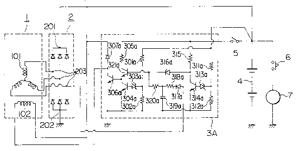
Fig. 1 shows an AC generator 1 equipped with a control
apparatus which is constructed in accordance with the present
invention. The AC generator 1 is in the form of a three-phase AC
2044444
generator having an armature coil 101 and a field coil 102, as in
the generator 1 of Fig. 2. The control apparatus of the
invention includes a rectifier 2 in the form of a full-wave
rectifier, a storage battery 4, a key switch 5, a starter switch
6 and a starter 7 in the form of a motor, all of which are
similar in construction and operation to the corresponding
elements 1, 2 and 4 through 7 of the aforementioned control
apparatus of Fig. 2. In addition to these elements, the control
apparatus of the invention includes a voltage regulator 3A which
is different in construction and operation from the voltage
regulator 3 of Fig. 2.
Specifically, the voltage regulator 3A of the invention
is constructed as follows. It includes a pair of generator-
voltage detecting voltage-dividing resistors 301a, 302a, a first
Zener diode 303a, a first control transistor 304a, a first base-
current supplying resistor 305a, a switch 306a in the form of a
power transistor, and a suppression diode 307a, which are the
same as, and connected substantially in the same manner as, the
corresponding elements 301 through 307 of Fig. 2. Other than
these elements, the voltage regulator 3A further includes a pair
of battery-voltage detecting voltage-dividing resistors 311a,
312a which are series connected to each other and which are
connected in parallel to the serially connected voltage dividing
resistors 301a, 302a, a second Zener diode 313a having a cathode
connected to a junction between the voltage dividing diodes 31la,
312a, a second control transistor 312a having a base connected to
an anode of the second Zener diode 313a and an emitter connected
204444~
to ground, a second base-current supplying resistor 315a
connected between the key switch 5 and a collector of the second
control transistor 314a, a first reverse-current checking diode
316a having an anode connected to the collector of the second
control transistor 314a, a second reverse-current checking diode
317a having an anode connected to any one of the input terminals
203 of the rectifier 2, a first smoothing resistor 318a having
one end thereof connected to a cathode of the diode 317a, a
smoothing capacitor 319a connected between the other end of the
first smoothing resistor 318a and ground, a second smoothing
diode 320a connected between the other end of the first smoothing
resistor 318a and the cathode of the diode 316a, and a transistor
321a having a base connected to the cathode of the diode 316a, an
emitter connected to the collector of the second control
transistor 304a and the base of the power transistor 306a, and a
collector connected to one end of the first base-current
supplying resistor 305a.
The control apparatus of the invention as constructed
above operates as follows. When the key switch 5 is first turned
on, the first control transistor 304a remains non-conductive due
to the non-conduction of the first Zener diode 303a since the
output voltage of the storage battery 4 is not so high as to make
the Zener diode 303 conductive. At this time, however, the
second Zener diode 313a is made conductive by the output voltage
of the battery 4, so a current is supplied from the battery 4 to
the base of the second control transistor 314a through the now
conductive Zener diode 313a. As a result, the transistor 314a is
2044~4
-
turned on so that a current flows from the battery 4 to ground
through the second base-current supplying resistor 315a and the
now conductive transistor 314a. Thus, no base current is
supplied from the battery 4 to the base of the transistor 321a
through the resistor 315a. Until this time, sufficient output of
the generator 1 is still not supplied to the base of the
transistor 321 through a generator signal smoothing circuit which
is constituted by the smoothing resistors 318, 320 and the
smoothing capacitor 319. Therefore, the transistor 321 remains
non-conductive, so the power transistor 306 is held non-
conductive. In this manner, unlike the aforementioned known
control apparatus of Fig. 2, the apparatus of the invention can
positively prevent the supply of current from the battery 4 to
the field coil 102.
Subsequently, when the starter switch 6 is turned on,
the starter 7 is energized to operate by the battery 4 so that an
unillustrated engine operatively connected to the starter 7 is
thereby started. On this occasion, the output voltage of the
discharging battery 4 decreases below a predetermined value
corresponding to a threshold voltage for the Zener diode 313a, so
that the Zener diode 313a and the transistor 314a are both made
non-conductive. As a consequence, a current flows from the
battery 4 to the base of the transistor 321a through the base-
current supplying resistor 315a and the diode 316a, making it
conductive. With the conduction of the transistor 321a, the
power transistor 306a is also turned on so that a current is
supplied from the battery 4 to the field coil 102. As the engine
204~444
is started, the generator 1 begins to generate electrical power
and a power generation signal in the form of an alternating
current as well.
When the starting operation of the engine has finished,
the starter switch 6 is automatically turned off to disconnect
the battery 4 from the starter 7. Thereafter, the battery 4 is
charged by the output voltage of the generator 1 to recover and
raise its voltage. When the voltage of the battery 4 thus
charged increases above a predetermined level, the transistor
314a again becomes conductive. At this time, however, a power
generation signal in the form of an alternating current is
supplied from the armature coil 101 of the generator 1 to the
smoothing circuit comprising the diode 317a, the resistors 318a,
320a and the capacitor 319a, where it is smoothed and converted
into a substantially constant direct current which is then
supplied to the base of the transistor 321a, thus holding it
conductive. As a result, the power transistor 306a is also held
conductive.
Subsequently, when the output voltage of the generator 1
gradually increases above a predetermined level corresponding to
the threshold voltage of the Zener diode 303a, the ~ener diode
303a and hence the first control transistor 304a become
conductive. As a result, the power transistor 306a is turned off
so that the field current supplied from the battery 4 to the
field coil 102 is decreased to reduce the output power of the
generator 1.
On the other hand, even if the key switch 5 is
204~4~
inadvertently turned on, there is no current supply to the field
coil 102 as long as the engine does not start to operate. In
addition, when the engine stops operating, the generator 1 of
course stops power generation or a power generation signal so
that the transistor 321a is made non-conductive to turn off the
power transistor 306a, thus cutting off the current supply to the
field coil 102.
In this manner, according to the present invention, when
the starter 7 begins to operate, a current is supplied to the
field coil 102 only if the generator 1 generate electrical power
or a power generation signal. In other words, the current supply
to the field coil 102 is stopped when the generator 1 stops
generating power or the power generation signal.
As described in the foregoing, according to the present
invention, even if a driver inadvertently leaves a vehicle with
the key switch 5 left on, or if the engine for driving the
generator 1 stops for some reason while the driver is operating
his or her vehicle on which the control apparatus of the
invention is installed, the generator 1 no longer generates power
or an output signal, whereby no current is supplied to the field
coil 102 of the generator 1. As a result, the discharge of the
battery 4 is substantially suppressed except for a limited amount
of control current being supplied to the voltage regulator 3A.
Thus, a so-called dead battery can be effectively prevented. In
addition, even when the voltage regulator 3A is an air-cooled
type in which the voltage regulator 3A is cooled by air produced
by the rotation of the generator 1, there will be substantially
12
_ 2044444
no heat generation at the voltage regulator 3A and hence no
thermal damage thereon since the field current is cut off due to
the stoppage of the generator 1.
13