Note: Descriptions are shown in the official language in which they were submitted.
2~
A Device for Heating Platelike Parts
The invention relates to a device for heating platelilce parts made of a deep-drawable
plastics material using contact heat and hot gases which are supplied to the part to be
heated by means of carrier plates, wherein two carrier plates are movable relative to
each other at least vertically to a common contact surfacej and gas distribution conduits
open in the contact surface.
With sintering operations and with this art in general, it is necessary to process
platelike parts using a device of the kind mentioned hereinabove, in order to weld or
also deep-draw platelike parts made of deep-drawable plastics material. The word"platelike" is used to denote workpieces which are flat or laminar, which are e.g. in the
shape of plates, shells, bars, strips or sheets. These kinds of platelike parts made of
df-ep-drawable plastics material are joined together, or are heated by the deep-drawing
process. They are placed in contact with so-called carrier plates, sa that the heat
energy is transmitted from the carrier plates to the platelike workpieces through
contact. The idea has also br en harboured of applying, alternatingly or additionally, hot
gases, preferably hot air, to the platelike workpiece to be heated, in order to improve
or accelerate the heating up or warrning process. After the heating process, the two
oppositely disposed carrier plates which have a common contact surface when theytravel together, arf~ displaced relative to each other in such a way that the platelike
parts or workpieces can be removed and conveyed to other processing stations.
I lowever, tests h~ve unfortunately revealed that the platelike workpieces to be heated
remain stuck to the contact surface, which is flat, for example, of at least one- or
two, in the case of particularly bad embodiments - carrier plates. With these tests, gas
distribution conduits have now also been arranged in the carrier plates so that the
conduits open into the contact surface through openings, with the effect that
cornpressed air can be used in helping to loosen a platelike part. In spite of this
feature, the heated platelike workpieces have not always been able to be properly
rernoved from the contact surface of the carrier plate. It has unfortunately been
shown, for example, that the injected air for the purpose of pulling off the platelike
part or blank from the carrier plate softens at the place where rsrnoval has already
been effected, and then no longer promotes detachment at the other places where there
is still strong adhesion between the softened platelike workpiece and the carrier plate.
: . ;
':
2 2 ~
The total air pressure is reduced at said leakage places so that gas distribution conduits
are of no use.
Even if the contact surface of the carrier plate is coated with a plastics material, such
as for example, teflon, removal of the platelike workpiece is not successful in the
desired way. It has even been shown in practice, that the platelike softened workpiece
clings to the layer of teflon and is removed together therewith from the carrier plate
by the use of compressed air, without the platelike workpiece even being removedproperly from the surface as a whole.
The aim of the invention is therefore to create a device of the kind mentioned in the
introduction, wherein the platelike parts can be removed properly from the heating
plates, so that damage to the heating device can be avoided, and so that the service life
of the device can be increased.
This problem is solved according to the invention in that each of the contact surfaces of
both carrier plates is surrounded by a frame-like rlosed outer edge without mouth
openings for the gas distribution conduits. In describing these measures it is best to
imagine the contact surface as being flat, althou~h it is even possible for there to be a
gas-tight closure when the contact surfaces of the two carrier plates are bent or curved
so that they match each other in the same way. An embodiment such as this is
encompassed by the present invention. However, in this description, it will be adequate
to rnention only the simpler design of a flat contact surface. To heat the platelike
workpieces made of deep-drawable plastics material, the plastics plate is placedbetween two carrier plates which can be moved together and apart relative to each
other, wherein according to the invention, not the entire contact surfac~ but at least
one frame-shaped edge at the periphery of the carrier plate comes into contact with
the plastics plate for the purpose of heating. This outer edge is designed without mouth
openings for gas distribution conduits, so that a barrier to gases is formed by this outer
edge which is closed in on itself like a loop, and which is disposed at the periphery of
the contact surface and thus also at the periphery of the plastics plate. In the region
inside the outer edge there are mouth openings for gas distribution conduits which are
capable of breaking a barrier of the afore-mentioned kind. By way of the inventive
measures it is ensured, however, that the plastics plate which is to be heated in the
region of the closed outer edge is clamped between two carrier plates in such a way
that the workpiece, i.e. the plastics plate is tensioned like a diaphragm. The plastics
plate can behave like a tympanum or diaphragm, so that when hot gases are introduced
into the one carrier plate and gases are sucked out onto the oppositely disposed carrier
plate. the plastics plate, i.e. the heated workpiece can advantageously be removed
:, ' ' . .:' : i ''.~ '
:. :
3 2 ~
properly from the one carrier plate and the contact surface thereof. When the plastics
plata is attached by suction to the oppositely disposed carrier plate, it can even be held
there. The disadvantageous drawbacks of the afore-described device whereby the
heated plastics plate partly remains on the carrier plate and is not removed because of
the resulting softened and sticky condition is avoided.
It is also expedient if according to the invention the contact surface has, in the region
inside the outer edge, at least one recess which is shallow in relation to the thickness of
the carrier plate. With a preferred embodiment, a plastics plate which is about 2 mm
thick is heated by being clamped between two carrier plates. The carrier plates are
heated and are preferably even acted upon by hot gases which issue from the mouth
openings in the region inside the outer edge of the contact surface.
These mouth openings are disposed in said region inside the outer edge which is
somewhat set back from the surface of the outer edge. With the embodiment under
consideration here of the plastics plate which is ~ mm in thickness, the shallow recess is
only 0.5 mm in depth. This is slightly set back with respect to the contac~ surface in
the region of the outer edge, so that this recess is only very shallow - in relation to the
thickness of the carrier plate as a whole which may, for example, be 20 to 30 mm. In
other words, the depth of the recess on the inner surface of the carrier plate in the
region inside the outer edge is oniy between 1 and 10%, preferably between 2 and 5%,
of the thickness of the carrier plate itself. A shallow recess of this kind is sufficient to
significantly increase the effect of the diaphra9m-like tensioning of the platelike
workpiece, which is surprisingly advantageous in that when a carrier plate is blasted
accordingly, the plastics plate, even if heated and softened, can be removed, without
more ado, from the inside surface of the carrier plate, i.e. from the contact surface and
also from tha recess. This removal operation is the actual aim of the inventive
measures, and the operation is also reliably ensured by the use of simple means.
It is also advantageous according to the invention if, in the region inside the outer edge,
the carrier plate has at least one insert which is at least partly gas-permeable and
which has a recess towards the free surface. In the preceoding exposition, account has
only been taken of the so-called inner surface of the carrier plate, i.e. the surface
which is opposite the corresponding surface of the other carrier plate~ By virtue of the
gas-permeable insert according to the features mentioned latterly, this inner surface of
each carrier plate is advantageously replaced by the region inside the outer edge of the
cnntact surface. In other words, in the rsgion inside the outer edge there is tool which
is inserted into the carrier plate, namely the insert which is at least partially
gas-permeable. It is true that the free surface thereof could be designed in one piece
with the outer edge, so that neither the flat contact surface nor continuous, one-piece
,
,
contact surface of the known devices results. However, this is not the aim of the
invention. According to the invention, the insert is instead provided with a recess, as
described already hereinabove in connection with the carrier plate. The insert also has
on the free upper surface thereaf a shallow recess which can be the above stated size in
depth. On the rear side, the insert is embedded in the carrier plate and has no free
surfaces. The one surface which is at least slightly free is instead disposed on the side
where the recess is provided, on the one hand, and which is disposed, on the other hand,
in opposite relationship to the carrier plate. Use of a gas-permeable insert permits an
improvement to the blowing away or detaching operation of the diaphragm-like
tensioned, heated plastics plate when hot gases are directed appropriately from the
carrier plate.
In theory, it would be sufficient if one or a plurality of mouth openings were to be
provided in the free surface of the insert, because then the diaphragm-like plastics
plate could be removed properly.
It is, however, particularly advantageous if the gas-permeable insert consists of porous
sintered material. This results in the gases issuing uniformly from that insert in the
region of its recess, so that the heated platelike workpiece is removed properly from
the respective surface of the carr;er plate or surface of the insert inserted therein.
In the art, sintering is the sticking together of powders to form solid bodies at
temperatures which are between about 2/3 and 3/4 of the absolute smelting
temperature. Therein, the sintered material is not smelted, or only partial smelting is
effected of mixing partners which may be present and which smelt to a small extent.
Stabilisation during the sintering process is effected by viscous flows~ vapour9condensing and diffusion processes on the boundary surfaces of the granules.
Sintered metals are particularly suitable for the inser~s according to the invention, that
is to say metals and alloys (sintered alloys) which are obtained by sintering metal
powders. Apart from sintered metals, it is also possible to produce fire-proof
materials, oxide ceramics, ceramic substances etc. In any case, sintered materials are
porous and are therefore particularly suitable for distributing gases which can be
injected on one side by pressure. Heated gases can, for example, be injected through
the gas distribution conduits through the mouth openings on the inner surface of the
carrier plates and thence into the pores on the rear side of the insert. In the region of
the afore-mentioned shallow recess, these heated gases then issue out at the free
surface of the insert and thus cause the diaphragm-like plastics plate held between the
carrier plates to be released, in the desired way.
- ', ,: i , : ;: ' ~ :
:, : :: : . :: :
.. ...
One particularly preferable embodiment of the invention is one where the contactsurface of two oppositely disposad carrier plates is flat, where the respective inserts
are designed like plates, and wherein the inner reverse surFace of the carrier plate has
mouth openings for the gas distribution conduits.
Therein, it is particularly favourable, if, according to another advantageous
embodiment of the invention, the contact surface of each elongate carrier plate has, in
the region inside the outer edge, a row o~ parallel intermediate peripheral bars disposed
at a distance from each other and forming a plurality of recesses between them. This
feature enables an elongate plastics plate to be heated, in order, for example, to be
able to deep-draw a plurality of containers in one piece from this one elongate plate.
Thought has been given to creating a device for deep-drawing shells which are open on
one side from a blank made of deep-drawable plastics material, wherein a deep-drawing
device such as this has both a deep-drawiny tool and complementary jaws which are
movable relative to each other in such a way that two of the afore-mentioned carrier
plates are oppositely disposed for a period of time, in order for the heating process for
the platelike workpiece to be carried out during that period of time. The deviceaccording to the invention can then be used to deep-draw shells which are to be stuck,
sealed or joined to one another inseparably in some other way along their edges, for
example. From one single plastics plate in the form of a workpiece, it is thus possible
to shape a plurality of open bowls simultaneously, to join them together if necessary
and to close them. It is thus possible to simultaneously manufacture, fill and close a
plurality of four~ 5iX, ten or more packs, for example.
Further advantages, features and possible applications of the present invention will
emerge from the following description of a preferred embodiment, given in conjunction
with the accompanying drawings, wherein:
Figure 1 shows the cross-sectional view through a pair of carrier plates which
are in operatiGn, one of which carrier plates is shown in perspective in
Figure 3, approximately along the broken line I-I,
Figure 2 shows a similar view to that in Figure 1, wherein, however, the
platelike part, the plastics workpiece plate, has been blown or sucked
onto the oppositely disposed carrier plate,
Figure 3 shows a perspective view of a carrier plate with a row of 11 inserts
arranged behind one another,
:
~ :
Figure 4 shows a broken away view, on a large scale, of a unit on the curvelV
in Figure 3,
Figure 5 shows, on a larger scale, and broken away, a unit along the line V-V in
Figure 3,
Figure 6 shows a cross-sectional view through a pair of carrier plat~s whlch ar~
in op~ration, similar to figur~ 1, however, of anoth~r pr~ferrsd second
~mbudim~nt, on~ of which carri~r plates i5 shown in perspectiv~ in
fi~ur~ 7, approximately along the brok~n line Vl-VI,
Figur~ 7 shows a p~rsp~ctive view of a carri9r plate with a row of ~lev~n Inser~
anang~d bahind on~anoth0r and
FTgure 8 shows a brok~n-aw~y view, on a large scale, of a unit on ~e cu~ve Vlll
in flgur0 7.
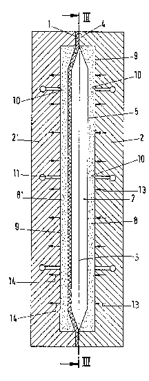
It can be imagined that a rectangular, elongate plate of plastics material is to be
heated as the workpiece, wherein this plastics plate which is only shown in
cross-section (platelike part) 1 is shown in two difl erent states in Figures 1 and 2.
The material of this platelike part 1 is a deep-drawable plastics material, from which a
pack can be manufactured, for example. The materlal can be a thermoplastics material
e.g. polypropene. PVC can also be used as the plastics material, wherein palypropene is
alsG known widely as polypropylene in the art. A plate which is manufactured from a
plastics material of this kind, or a shell which is deep-drawn from this plate, or a pack
which is formed from one or two shells then consist of parts and materials which can be
reused properly and which decompose easily (in contrast to compositP mat~rials, such as
for example paper coated with plastics material3. With a particularly preferred
embodiment~ it is possible for the plastics material, e.g. the polypropene. to be filled,
wherein chalks. mlca, talo, gypsum or the like may be used as fillers. In practice,
filling degrees of up to 7û%, preferably 60%, have proved favourable. It has be~n shown
that these kinds of filled plastics materials decompose very easilv, on the one hand,
without more ado, of course, and that they can be reworked or recycied using simple
methods, and that, on the other hand, the properties of a plastics material are not
adve~sely affected. These l<inds of filled plastics materials are therefore mostimportantly deep-drawable and sealing.
The carrier plate 2 shown in perspective in Figure 3 is the right-hand part in Figures 1
and 2, whilst the oppositely disposed carrier plate is denoted in Figures 1 and 2 by the
reference numerals 2'. In Fiyure 3, a view is taken of the contact surface which is
generally denoted by the reference numeral 3, and which contact surface is composed
of the sum of three sections, namely a frame-like closed outer edge 4, the region 5
inside the buter edge 4 and the row of intermediate peripheral bars 6 arranged at a
spacing b from one another and extending parallel to one another, which intermediate
peripheral bars form a plurality of the afore-mentioned recesses 5 - ~ccording to the
illustration in Figure 3, eleven recesses 5 along one outer edge 4 and ten intermediate
peripheral bars 4.
Each carrier plate 2, 2' is designed as an elongate parallelepiped. If the two carrier
plates 2, 2' are placed against each another as shown in Figures 1 and 2, then they make
contact at the common contact surface 3~ which, in the exaggerated illustration of
Figures 1 and 2 appears only to coincide at the outer edge 4. Actually, it is also
possible to add to the contact surface 3 the region 5 inside the outer edge 4, because
this is only set back from the common central line and the contact surface 3 by the
distance a (Figure ~) of e.g. 0.5 mm. The shallow recess with a depth a of about û.5 mm
can scarcely be seen by the naked eye, but this recess, denoted by the referencenumeral 7, is very important. The recess 7 is disposed in front of the region 5 inside t~e
outer edge 4.
Each of the carrier plates 2 or 2' is provided on the inside thereof, i.e. on the side which
is oppositely disposed to the carrier plate, with a recess, which can be manufactured by
milling or the like, and which is partially filled by an insert 8 or 8'. The irregularly
distributed dots in Figures 1, 2 and 5 indicate that the insert a is porous, a sintered
metal, for example. The region 5 inside the outer sdge 4 is formed in this embodiment
by the surface of the insert 8, or the free surface of the insert 8 is equal to the region 5
inside the outer edge 4. Nonetheless, the material beneath the outer edge 4 is a metal,
e.g. aluminium. from which the carrier plate 2 or 2' is formed, whilst the insert 8 is the
afore-mentioned porous sintered metal.
The surface on the rear side of each insert 8, 8' coincides with the inner surface 9 of
the carrier plate 2, 2'. Disposed on this surface there are mouth openings 10 which
communicate with bores for compressed air 12 through gas distribution conduits 11. In
this way, compressed air can come from the compressed air bores 12 via the gas
distribution conduits 11, to the inner surface 9, e.g. the carrier plate 2, in order to be
blown away in the direction o~ the arrow 13 through the porous insert 8 and over the
.
: .
2 ~
region 5 inside the outer edge 4. In reverse, the same thing happens by means of the
carrier plate 2' (Figure 2) where the compressed air is then blown in the direction of the
arrows 13'.
Accordingly, on the respectively oppositely disposed side, the carrier plate 2' can be
responsible, as shown in Figure 1, for suction in the direction of the arrows 14 or, in
reverse, when in the condition shown in Figure 2, ln the direction of the arrows 14'.
;
Each recess 7 is shallow, i.e. its depth a is only e.g. 0.5 mm~ and it is produced by
milling or erosion in the insert 8, 8'. The recess 7 is shallow in relation to the
thickness D of the carrier plate 2, 2', which can be between 20 and 50 mm, preferably
between 25 and 40 mm in thickness. for example.
With the practical embodiment, on the contact surface 3 of the carrier plate 2
(Figure 3) there are eleven inserts 8, each between 1 and 200 mm in length, and having
a height h of 100 mm. The total length of the carrier plate 2 is thus greater than 1 m.
An appropriate plastics plate which is in the form of a platelike part 1 with the same
dimensions as the entire contact surface 3 of the carrier plate 2 is adjusted ar,d placed
between two carrier plates 2, 2'. Three compress~d air bores 12 pass through each
carrier plate 2, wherein four gas distribution conduits 10, for example, leave sach of
these bores in each region 5 inside the outer edye 4 and the intermediate peripheral
bars 6, so that the inner surface 9 of the carrier plate 2 and thus the rear surface of the
insert 8 can be properly aired or ventilated (compres;ed air or vacuum).
The plastics plate inserted between the two carrier plates 2, 2' is a platelike piece
which is to be heated, and it is first of all disposed somewhat along the common line 3
in Figure 2, i.e. between the two contact surfaces. In order to arrive at the condition in
Figure 1, compressed air is now blown, from the right in the direction of the arrow 13
from the mouth openings 10 to the left into the inserts 8 and through these into the
space of the rscess 7. At the same time, hot air is sucked out in the direction of the
arrow 14 onto the oopositely disposed side with the carrier plate 2'. The hot air
introduced and the heated surface of the carrier plates heat the platelike part 1, which,
in the exaggerated position shown in Figure 1, rests on the surface in the region 5 of the
insert 8.
The two carrier plates 2, 2' can now be removed properly from each other, and by virtue
of the air sucked in the direction of the arrows 14 in the left carrier plate 2' in
- , .., :. .. . . . . .. ... .
- : . . .:,,, -
.: ., . :
i: . ... ':1 .
Figure 1, the platelike part 1 can be kept attached. For example, the cal~rier plate 2'
could be moved vertically into another position, and then be positioned in opposite
relationship to anoth~r carrier plate 2, in order to arrive at the state shown in Figure 2.
If the intention is to bring the platelike part 1 which has been further heated into the
condition shown in figure 2, then the currents of compressed air and of sucked air are
diverted, whilst the platelike part 1 remains clamped like a diaphragm in the outer
edge 4. On the ~eft carrier plate 2', compressed air is blown in the direction of the
arrow~ 13' behind the inse~t, whereby the diaphragm-like, clamped, platelike part 1 is
immediately lifted, and c~mes to rest on the surface of the oppositely disposed insert 8
in the way shown in Figure 2. This is also promoted by the air ~Nhich is sucked off
through the right-hand carrier plate 2 in the direction of the arrow 14'. It is to be
understood that the left-hand carl~ier plate 2' can now b~ removed. Nhilst the platelike
heated part 1 can be held by suction on the right~hand carrier plate 2.
The praferr~d secorld 2mbodiment is shown in figures 6 to 8. Similar parts are provided
thsreby with ~imilar re~0r~nce numerals so that on~ can recogni~ the similarity of thase two
~mbodim~n~s.
In figur~ 7 th~ carri~r plate is not shown with COlllpl~ Ci ~r bor~s anci ~as dis~lbu~on
conduits, howevar, one can imaglne similar solution~ a~; with the othQr ~mbodim~nt accordln~
to flyur~ 3, axcapt th~ fact In thc s~cond embodim~nt according to flguras 6 to 8 ~hat f~wer
ga3 di tribution conduils 11 dlscharge in the inner surface 9 of the carrier plate 2 and 2'
r~sp~cUv~ly.
50 for ~xample figur~ 6 shows in 0ach carri~r pl~ts 2 only one compressed air bore 12
approxim~ly in ~c middle from which bore some gas disSributien condui~ xtand
la~raliy in the direction to the common contact surfacs 3 distsibuted oc0r tha langth of thQ
carrier pl~e, which gas distributlon conduits 1 t dischar~a with the mouth op~ning 10 ther~of
in th~ inner surface 9.
Th~ largast and most import~nt differencc betwssn th~ second embodiment accordin~ to the
figurcs 6 to 8 in comparlson to tho flrst ernbodim~nt consists in a small r~cess 15 In ~9 outar
adge 4 of tha carrier plate 2, 2' respectively. This rece~s 15 do~s not reach entirely the outer
cdg~ 16 of tha carrier plat~ but tarminates in a distanca ahead th~reof in a st~p. This step
is denominat~ci with 17 and appears as a line in figures 7 and 8. Outsids this line Ule two
carrisr plates 2, 2' contact each oth~r as is shown for ~xample in figur~ 6, wi~out a work-
:,
, . ~
.,
o
pi~ca laying inb~tw~n, thus witheut a plate-like part 1 laying ther~between. The tot~ outer
ed~e 4 is sufround0d outside by the line 16, and batween ~he lines 16 and 17 the hvo t901
parts are ioca~ed. i.e. thus the two carrier plates 2 and 2' are laying on each other with
pressur~ force. The depth of the frame-shaped recess 15 is choos~n larg~r ~an half the
~hicknass of ~ work-piec~, thus ~he plate-like part 1. Consequently in tha ar~a of ~s ree~ss
15 th~ plat~-like part 1 is raceived and accommodated, respectively, without any pr~ssure
forc~, even when the two earrier plates 2, 2~ are laying against eneanother and are prsssed
against each other with high pressure.
In contrary to bhe pr0ceding 0mbbdiment in this preferred embodiment eare is taJsen for that
the plate-lik~ part 1 is not pressed by mechanical forces in the marginal area bet Neen the
lines 16 and 17. Tha advance of this last described embodiment according to figures 6 to 8
lles in that af2Or the heatin~ of the plate-liks part 1 this will be removed and detacheci,
respectiv~ly In a r~liable and exact manner from the respective carrier plate, even In ~he
margin~ area. ~ecaus~ the work-piace~ Ws is the pla~e-like part 1 expands som*what if
h~ated, the depth of the recsss 15 is somewhat larger than haif U~a thlckness of ~ work-
pi0ce, i.e. ~he plal~lika part 1. In tha contacting or compressing conditlon of fl~ure 6 the total
h~ight of bo~ r~ s 15 Is by 1/10 mm up to 5/100 mm iarg~r than th~ thickn~ss of th~
plat~-lik~ part 9, i.~. ~ickness of the plastics material. Eiven dutin~ heating thus it is avoided
in an advan~ous mannar, that tha work-pieo~ Is not prass~ci by mochanicai forc~s,
althou~h in ~ contacted or compress~ condition of figura 6 Ule carrier plates 2, 2'
substantially provide a sealing outslde at the margin or adga.
Instead of th~ porous in~ert 8 the air or gas from U~e gas distributlon conduits 11 can be
appllad to thn pla~like part 1 by fine slo~;, too.
~, '