Note: Descriptions are shown in the official language in which they were submitted.
F Hw/Aw/4Storlc
MET~IOD AND DE~ICE FOR IN~ECTING A PIECE OF ~EAT WIT~i A LIQUID
SUBSTANCE SUCH AS I~RINE
The invention relates to a method for introducing
liquid substances such as brine or paste into a meat piece,
wherein the liquid substance is injected into the meat piece.
The in~ention relates more particularly to the inject-
ing of brining liquid into a piece of meat without needles orother mechanical means being inserted into the piece of meat.
To this end the brining liquid is sprayed at high pressure
from a spray nozzle into the meat which, in the known me-
thods, results in the surface of the meat being damaged.
The invention has for its object to improve the above
mentioned method such that this damage does not occur.
The method according to the invention is distinguished
in that during injecting the piece of meat is held in contact
with one or more spray nozzles for injecting the liqllid
substance.
The contact prevents the injection stream being atomi-
zed prematurely, that is, outside the meat, which would
result in a greater spraying spot.
According to a further development the meat piece is
deformed using mechanical means to a slab of predetermined
thickness and with a certain width. Owing to the deforming of
the meat to a determined thickness the required injecting
pressure is reduced, which also contributes towards reducing
the damage to the meat surface.
It is further recommended in each case to subject the
meat piece according to a determined grid to at least one
stream of liquid substance under superatmospheric pressure.
The most homogeneous possible distribution of the brining
liquid in the meat is thus obtained, wherein it is recom-
mended according to the invention to make the grid size a
maximum of 2 cm, and preferably 1 cm.
To avoid damage to the meat, particularly red meat,
the invention proposes to make the thickness of the meat
piece for deforming a m~ximum of 2 cm so th~t with a penetra-
tion depth of 1 cm 50% o~ the meat is already cured.
The invention further relates to a ~evice for perform-
ing the above stated method, which device is provided with a
frame and one or more spray nozzles for the liquid substance
carried by the frame, which device is distinguished in that
means are arranged for holdiny the piece of meat in contact
with the or each spray nozzle. According to a further deve-
lopment of the device according to the invention it is embo-
died with means for deforming the piece of meat, in particu-
lar close to the spray nozzles.
With s~ch an embodiment the meat piece is carried
along the spray nozzles whereby these latter can have a
stationary disposition, which facilitates the supply of
brining liquid under high pressure and control of the compa-
ratively short spraying times.
In a preferred embodiment the transporting means are
embodied as a conveyor carrying the piece of meat.
In preference the spray nozzles are disposed in a line
perpendicular to the conveying direction of the meat piece,
wherein the conveyor can be embodied as an endless belt
whereof at least one reversing roller is arranged adjacent to
the row of spray nozzles.
According to the invention the deforming means can
effectively be embodied as a pressure roller whereof the
rotational shaft is situated opposite the row of spray noz-
zles. According to the invention this rotational shaft can be
distance adjustable relative to these spray nozzles.
According to another embodiment the means for deform-
ing the meat piece can be embodied as a pressure chamberhaving two substantially parallel walls, in the one of which
the row of spray nozzles is arranged and the other wall
whereof converges xelative to the one wall towards the spray
nozzles, and wherein the transporting means is a piston
movable reciprocally between the two walls.
Above mentioned and other features of the invention
will be further elucidated in the figure description herein-
below of a number of embodiments. In the annexed drawing:
fig. 1 shows a perspective view of a first embodiment
of a device according to the invention provided with an
endless conveyor with co-acting pressure roller,
fig. 2 shows a detail of the ~evice of fig~ 1 on
enlarged scale with partly broken away parts,
fig. 3 shows a further detail of the ~evice of fig. 1
and 2 in perspective view with partly broken away parts,
fig. 4 i5 an upright section of a second embodiment of
the device according to the invention provided with a pres-
sure chamber,
fig. 5 shows a grid having shown therein the brine
distribution in the piece of meat obtained with the method
according to the invention.
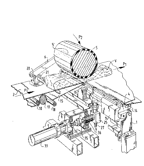
The device according to fig. 1 consists of a frame 1
of random type, which in the embodiment shown is made from
tube pro~iles, this such tha~ two endless conveyors 2, 3 can
be supported in line with one another. Received between the
two conveyors 2, 3 is a beam 4 having arranged therein spray
nozzles to be further elucidated hereinafter, this such that
these are arranged in a line perpendicular to the conveying
direction Pl. A pressure roller 5 which serves as deforming
means for the meat is rotatably arranged opposite and above
the beam 4, wherein it is noted that the rotational shaft of
the roller 5 is received at either end in each case in a
swivel arm 6.
With reference to fig. 2 and 3, the spray beam 4 is
embodied as a beam of trapezium-shaped cross section having
a number of ~ertical bores in each of which is received a
spray nozzle 10. The bores communicate on the underside with
a common feed channel 11 which communicates with a feed
conduit 12 which is connected in a manner to be designated
~0 below to a liquid feed system 13. The spray nozzle beam 4 is
held in two frame beams 14 which form part of the main frame
1.
In the embodiment shown the feed conveyor 2 is an
endless belt 15 provided with a reversing member 16 extending
parallel and close to the side of the spray nozzle beam 4.
The belt 15 is further trained around a tensioning or drive
roller 17 with associated guide rollers 18. on the feed side
the belt is embodied with a second reversing roller 19.
The discharge conveyor 3 is embodied in similar man-
ner, with the undsrstanding that it is arranged mirror sym-
metrically relative to the spray nozzle beam 4. The drivingof both conveyors takes place such that the upper part moves
in the direction of the arrow Pl.
The roller 5 embodied with a covering of elastic
material can be of any type but is of a weight and is biased
in the direction of the arrow P2 such that a meat piece V to
be moved forward on the conveyor is subjected to a determined
pressure such that the piece of meat undergoes a deforming at
the position of the spray nozzle beam 4, whereby the thick-
ness is reduced.
As already stated above, the roller 5 is freely rota-
table on a rotational shaft 5' which is mounted in swivel
arms 6 which are mutually connected with a coupling shaft 20
which is received in a fork-like bearing part 21 which sup-
ports on the frame 1. The coupling shaft 20 runs through
beneath the upper part of conveyor 2. If use is made of a
determined biasing of the roller 5 in the direction o~ the
spray nozzle beam 4, hydraulic cylinders (not shown) can then
act upon the arms 6.
There now follows a description of the liquid feed
system, the liquid whereof serves as injection liquid for the
meat piece V.
Arranged under the spray nozzle beam ~ is a valve
housing 25 of which the intake opening 26 is connected to a
feed conduit 27 for the injection liquid, for example brine
with additives, subject to the meat piece for processing.
Arranged in the valve housing 25 is a non-return valve
28 in addition to a non-return valve 29. Each non-return
valve is embodied here as a ball that is movable in a chamber
and which can close off and release a passage opening located
thereunder.
Arranged between both ball valves 28 and 29 in the
passage 30 of the valve housing 25 is a branch bore 31 in
which a plunger 32 is reciprocally movable. In the embodiment
of fig. 2 the plunger is driven by a hydraulic cylinder 33 by
connecting the piston rod 34 thereof via a coupling 35 to the
plunger end part 36 of plunger 32.
Finally, it is noted that the outlet port of the upper
valve part 29 is connected to the inlet bore 12 of the spray
nozzle beam 4.
The a~ove device operates as follows.
When a randomly shaped piece o~ meat i5 laid on the
upper part of the feed conveyor 2 it is carried in the direc-
tion of arrow P1 to the spray nozzle beam 4. At this location
the piece o~ meat V is brought to the correct thickness by
the pressure roller 5 an~ liquid in the spray nozzles 10 is
in each case sprayed, preferably every centimetre as seen in
the direction of arrow P1, into the meat on the underside.
Spraying takes place for a very short time, between 12 and 60
milliseconds, in order to prevent stripes on the underside of
meat piece V. With a correct distance interval between the
spray nozzles 10, for instance 1 cm, a one centimetre grid
can be obtained, see fig. 5. By selecting the correct spray-
ing pressure and spray velocity a good penetration depth of
the liquid into the meat V can already be achieved, whereby
the meat is contaminated not only regularly but also uniform-
ly, see the concentric circles around the spraying positions
in the grid according to fig. 5. A uniform distribution of
the brining liquid in the meat V is herewith assured.
Spraying of the liquid is effected by periodically
moving the plunger 32 reciprocally in the branch chamber 31
of the valve housing 25. This is carried out in one case by
actuating the cylinder 33 according to fig~ 2 and in the
other by the motor 39 as in fig. 3.
When the plunger 32 moves to the left liquid will be
drawn via the lower valve 28 into the chamber 30, wherein
after the plunger 32 has moved back the liquid in chamber 30
is placed under pressure, which results in the closing of the
lower valve 28 and the opening of the upper valve 29, whereby
the liquid can flow via opening 12 and channel 11 to the
spray nozzle beam, whereafter it can exit to the outside via
the spray nozæles 10.
Owing to the direct contact of the outflow opening of
the spray nozzle 10 with the underside of the meat piece V
the bottom surface of the meat piece V will not be damaged.
Shown below is a survey of test results on different
sorts of meat.
Chicken fillet:required pressure 90 bar
sprayer orifice0.13 mm
penetration to15 mm
weight increase4-15 %
maximum increase 25 %
Chicken legs: required pressure 70 90 bar
sprayer orifice0.13 mm
penetration depth 10-15 mm
weight increase4-15 %
maximum increase 20 %
Pork: required pressure 200 bar
(shoulder) sprayer orifice0.13 mm
penetration depth 25 mm
weight increase4-30 %
maximum increase 25 %
Pork: required pressure 250 bar
(bacon backs) sprayer orifice0.13 mm
penetration depth 30 mm
weight increase4-20 %
maximum increase 25 %
Salmon: required pressure 60-80 bar
(smoked salmon) sprayer orifice 0.13 mm
penetration depth 20 mm
weight increase3-7 %
maximum increase 5 %
There now follows a description of an alternative
embodiment according to fig. 4. In the schematic depiction of
this embodiment the spray nozzle beam 4 and the discharge
conveyor 3 are the only similarities to the embodiment of
fig. 1-3. The spray nozzle beam 4 forms part of the bottom
wall 40 of a pressure chamber 41, the top wall 42 of which
extends parallel to the bottom wall 40. The sides of the
pressure chamber 41 axe closed by fixed wall portions tnot
shown). In the pressure chamber 41 a rectangular piston 43 is
reciprocally movable by a hydraulic cylinder 44. The wall 42
located opposite the bottom wall 40 converges from the point
45 in the direction of the spray nozzle beam 4, whereby a
narrow passage opening is obtained at the position of the
spray nozzles. Behind the spray nozzle beam 4 the pressure
chamber widens again, wherein the open rear part debouches
abov~ the upper part of the discharge conveyor 3.
The device operates as follows: By actuating the
hydraulic cylinder ~4 the rectangular piston ~3 will move to
the right in fig. 4, wh~reby the piece of meat pre-arranged
in the pressure chamber 41 is transported in the direction of
arrow P1 and pressed through the narrow opening at the spray
nozzle beam 4, whereby a deforming of the meat piece takes
place to the desired thickness. The operation of the spray
nozzle beam 4 can take place in a manner corresponding to
that described above whereby the meat piece can be processed
in accordance with the same grid pattern as in ~ig. 5. The
piece of meat V is further carried away on the discharge
conveyor 3~
The invention is not limited to the above described
embodiments, wherein a kinematic reversal of the movement of
the meat relative to the spray nozzles is conceivable. It is
equally possible in a particular embodiment to move the spray
nozzles relative to the stationary piece of meat V in order
to obtain the desired spraying grid.
In addition the spray nozzles do not have to be dis-
posed in a line but may have any suitable configuration. It
is furthermore conceivable to arrange the spray nozzle movab~
ly in two coordinate axes whereby one spray nozzle would be
sufficient.
The common feed chamber for all spray nozzles can of
course be replaced by a separate feed for each nozzle, thus
enabling volume control per nozzle.
*****