Note: Descriptions are shown in the official language in which they were submitted.
2045295
-- 1
BACKGROUND OF THE INVENTION
The present invention relates to wooden
structural members which can be used as beams, joists,
studs, posts or the like.
S Hitherto, where savings in weight or material
cost is of importance, conventional lumber which is
rectangular in cross-section, has been substituted by
wooden I-beams or X-beams.
For example, a wooden I-beam is disclosed in
United States Patent 4,191,000 issued March 4, 1980 - L.R.
Henderson. The tongue-and-groove connections between the
central web and two outer flanges of this type of wood I-
beam may limit the allowable design load of the beam given
certain beam width and depth dimensions. This is due to
the strength capacity of the web and flange connections,
which is determined mainly by the amount of contact area
available between the web and the flange, which is usually
limited. Moreover, the shear strength capacity of typical
tongue-and-groove connections in wooden I-beams cannot be
readily increased, unless the design of the connection is
itself altered.
A further drawback characteristic of wooden I-
beams is differential thickness swelling, and which is
encountered between the flange and web at the tongue-and-
groove connection. When moisture is absorbed, the webmember tongue swells, whilst the groove in the flange
member shrinks; and vice versa, ~hen moisture is desorbed.
Differential lateral movement repeated over time will
2045295
-- 2
result in separation of the glue bond between the tongue
and the groove, or in splitting of the flange members at
the tongue-and-groove joint location.
Christ-Janer in United States Patent 4,446,668
issued May 8, 1984 discloses a novel wooden X-beam
construction which employs, in cross-section, two webs
which are centrally joined together along their length and
which have disposed therebetween, top and bottom wedge
shaped flanges. The Christ-Janer form of X-beam
construction is very restricted in terms of manufacturing
flexibility. Sizes of beams are not easily changed, as
each time the configuration is changed, a new moulded shape
of the web members, which accommodate the flanges, is
required. Problems due to thickness swelling or shrinkage
also exist, since the opposed web members, which are
centrally connected, resist lateral movement resulting from
swelling or shrinkage of the wedges disposed above and
below the central connection of the two webs. As a result,
lateral swelling of the wedge flange members exerts a
tensile stress on the connection between the two web
members. Conversely, lateral shrinkage puts a tensile
stress on the connection between the flanges and the web
members.
SUMMARY OF INVENTION
The novel wooden structural member of this
invention, like the known wooden I-beams, is constructed
from two flange elements, and a single web element.
2045295
However, in cross-section, it has the appearance of a
X-beam.
In accordance with this invention, the elongate
wooden beam, post or the like structural member, like its
I-beam counterpart, has spaced apart, planar and parallel,
first and second beam surfaces twidth faces) extending the
length of the member. However, and unlike the I-beam, the
elongate web section, in cross-section, is inclined and
extends diagonally across the member from one edge of the
first beam surface to an edge of the second beam surface.
Further, and in lieu of I-beam flanges which are
rectangular in cross-section, first and second wedge-
shaped members or flanges, preferably each made up of solid
wood and which extend the length of the member, are
disposed on either side of the web. Each wedge shaped
member (also referred to herein as a flange) has an
exterior wall respectively forming all or a major portion
of the first and the second beam surfaces and two sidewalls
tapering relatively inwardly in a direction away from the
exterior wall, with one of the sidewalls of each wedge
shaped member being securely attached to the web sidewalls.
As a result, the structural member, in cross-section, has
a X-beam appearance and this cross section is continuous
along the length of the structural member.
In conventional wooden I-beam construction,
alignment between the top and bottom flanges is critical to
strength of the connection; particularly where the area of
contact between the flange and the web member is small.
2045295
-_ - 4
Since the wedge shaped flanges of the subject invention are
effectively aligned with the elongate edges of the web,
alignment between the flanges is easy to achieve.
It will also be apparent that wooden structural
members manufactured in accordance with this invention can
be fabricated so that the contact areas between the flanges
and the web can increase proportional to beam depth or to
the beam design bending moment, in order to ensure adequate
shear capacity. Furthermore, and in addition to being able
to control the bonded area between the flange and the web,
the beam width, depth, and flange cross-sectional area
versus amount of web cross-sectional area, can also be
manipulated in order to optimize for strength and/or cost.
The elongate web can be made up from solid wood,
for example a plank, or preferably from a wood composite,
such as waferboard, orientated strand board, particleboard
or plywood. The flanges similarly can be made up from
either solid wood or wood composites, such as laminated
veneer lumber, glue laminated lumber, particleboard or
plywood.
In cross-section, the structural member of this
invention is confined within an imaginary rectangle, the
top and bottom sides of which are respectively in the same
planes as the first and second beam surfaces and preferably
correspond to the transverse length of the beam surfaces.
The angle of web is a function of the desired
width and depth of the finished structural member, and can
be expressed as follows:
204 ~2~ ~
_ - 5
~ = Tan~1 (h/w)
where:
is the angle of inclination of the web
h is the depth of the beam measured between
the two opposite beam surfaces, and
w is the width of the structural member
Advantageously, the wedges which are placed on
either side of the web section can be produced simply by
diagonally ripping rectangular wood stock such as 2 x 3
inch or 2 x 4 inch lumber, or by sawing round logs through
the centre of the logs. Furthermore the wedges, when
secured to opposite sides of the web section, result in a
balanced beam element, having a neutral axis of rotation,
extending longitudinally and centrally through the web
lengths.
The cross-section of the wedge shaped flanges is
preferably triangular or trapezoidal, and preferably that
of an isosceles triangle with the tapering sidewalls of the
flanges gradually decreasing towards the neutral axis of
the beam. A vertical load applied perpendicular to the
beam surfaces passes through the centroid of the web
member, corresponding to its neutral axis. This
configuration is efficient in resisting the bending moment
as experienced in beam loading applications, since the
normal stress distribution in beam cross-section due to the
bending moment is highest at the top and bottom surfaces
and gradually reduces to zero at the neutral axis.
The point of intersection of the two tapering
- 6 - 204~295
walls of the wedge, relative to the beam surface from which
the wedge extends, for strength purposes, is preferably
outboard of the neutral axis and extends an amount equal to
or greater than one half the depth of the beam.
In keeping with the foregoing there is provided
in accordance with the present invention an elongate wooden
structural member having a width dimension which is
significantly less than its height dimension and which is
constructed from first and second substantially identical
longitudinal flange elements that are wedge-shaped in
cross-section and which are securely fastened to a wooden
web section, said web section having opposite sidewalls and
a length corresponding to that of said structural member,
said structural member being of constant cross-section
throughout its length and further characterized by:
(a) a first pair of longitudinally extending
opposite beam surfaces and a second pair of longitudinally
extending opposite sides, an outline of said first pair of
beam surfaces and second paid of sides, in structural
member cross-section, being contained within an imaginary
rectangle where such outline of said pair of beam surfaces
correspond to respective ones of two parallel sides of said
imaginary rectangle;
(b) said web section, in structural member
cross-section, extending diagonally across said imaginary
rectangle at an angle, and said first and second
longitudinal flange elements being respectively disposed on
oppo5ite side walls of said web; and
2045295
_ - 7
(c) said first and second flange elements each
having a first wall the two of which form at least a major
portion of respective ones of said first pair of beam
surfaces, a second wall the two of which abut respective
ones of said opposite side walls of said web and a third
wall the two of which form a portion of respective ones of
said second pair of sides, and wherein, in structural
member cross-section, the length of said second and third
walls of the respective first and second flange elements
are each greater than the length of said first wall.
There is also particularly provided in accordance
with the present invention an elongate manufactured slender
member having first and second longitudinal narrow edges
and made of wood and wood composite elements and intended
for use in place of a length of a solid piece of lumber,
said member being of constant cross-section throughout its
length and comprising:
(a) a first elongate web element having opposite
sides and opposite longitudinal edges, comprising a piece
of a manufactured wood composite panel, said web element
extending the length of said member;
(b) second and third longitudinal respective
wedge shape elements each of which is solid wood and has a
length corresponding to the length of said member, said
first and second elements being disposed respectively on
opposite sides of said web and adjacent respective opposite
longitudinal edges thereof, said wedge shape elements each
having a first wall, a second wall and a third wall with
- - 8 - 2045~95
said first wall, in member cross section, being
substantially shorter than said second and third walls,
said first wall of said wedge shape elements forming a
major portion of respective first and second opposite
longitudinal narrow edges of said member; and
(c) means securing said wedge shape elements to
said web with one of said second and third walls of the
respective wedge shape elements abutting said web.
BRIEF DESCRIPTION OF THE DRAWINGS
The invention is illustrated by way of example in
the accompanying drawings wherein:
Figures 1 through 3 represent, in cross-section,
different embodiments of wooden structural X-beams
constructed in accordance with this invention; and
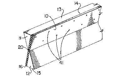
Figure 4 is a partially cut away perspective view
of the X-beam illustrated in Figure 3.
DETAILED DESCRIPTION OF THE DRAWINGS
In the accompanying drawings, the same reference
numerals have been used to denote like parts.
As seen in Figures 1 through 3, each beam is made
up from a web or plate section 10 and top and bottom wedge
shaped flanges 11 and 12 disposed on either side of web 10.
The flanges are securely attached to the web employing an
adhesive or mechanical fastening means, or both (not
shown).
As illustrated, the first or upper flange 11 have
_ - 9 - 2045295
an exterior wall 13 which, together with edge 14 of web 10,
forms the first or top beam surface of the structural
member. Similarly, exterior wall 15 of the second or
bottommost wedge shaped flange 12, together with the bottom
edge 16 of web 12, forms the second or bottom beam surface
of the structural member. Broken lines 40 represent the
two opposite sides of an imaginary rectangle where the
remaining two opposite sides consist of the above described
first and second beam surfaces.
Relative to the top and bottom beam surfaces, the
centroid of the beam, which corresponds to the neutral axis
of rotation of the beam, is illustrated at point 20.
From a strength standpoint and given all outer
dimensions are equal, it will be evident that beams
constructed in accordance with that of Figure 3 are the
strongest and involve assemblies where the flanges, in
cross-section each constitute an isosceles triangle with
the apex of the triangle terminating at least at the mid-
point of the depth (or height) of the beam represented by
broken line 50 which also extends through the neutral axis
point 20. Those flanges which are in the form of truncated
isosceles triangles, as seen in Figure 2 are next in load
bearing strength, even though the glue depth of the wedge
is equivalent to the glue depth of the wedge seen in Figure
1. As will be apparent, the glue depth of the Figure 3 X-
beam is significantly greater than in Figures 1 and 2.
With reference to Figure 4, as illustrated, the
web 10 is constructed from waferboard with flanges 11 and
20 45295
-- 10 --
12 glued (not shown) on either side thereof and also
mechanically attached employing nails 41.
By the very nature of the cross-sectional shape,
structural members fabricated in accordance with this
invention generally provide greater strength and stiffness
capacities than solid lumber having the same quantity of
wood. Their flexural strength, however, will be averaged
between the strengths of the wood flange and the web,
which, in effect, is a load-sharing system. Because of
load sharing, the strength properties of beams based on the
present configuration will be less prone to strength
variation as found in wooden I-beams, and which results
from localized defects in either the flanges or the web
member of the I-beam.
The strength and stiffness characteristics of the
novel structural member of this invention can be calculated
on the basis of the component strength and stiffness
characteristics, assuming fully composite beam behaviour.
This assumption is regarded as valid because of the use of
glue for the connection.
By way of illustration, two sets of beams, each
of a different size, were fabricated in accordance with the
invention and tested in bending and in compression to
simulate its use as a beam or columns. One set of beams
were made from No. 2 and Better 2 x 3 inch spruce lumber
ripped diagonally for the flange elements and a 7/16" thick
waferboard for the web element, forming a X-beam with an
outer dimension of 2" x 7" in cross-section. The other set
-- - 11 - 2045295
of beams were made from No. 2 and Better 2 x 4 inch spruce
lumber ripped diagonally as the flanges, employing the same
thickness waferboard as the web element, producing, in this
case, a X-beam with an outer dimension of 2" x 8".
As indicated above, each piece of lumber was
halved diagonally forming two isosceles triangular wedges.
A commercially available construction glue of a polyvinyl
acetate resin was used for the connection between the
flange and the web member, supplemented by two rows of 6
penny common nails spaced at 6" on centre. The between-
row distance was 2 inch in the case of the 2" x 7" beam,
and 3" in the case of the 2" x 8" beam. The bending test
was carried out in accordance with ASTMD198-84 "Standard
Methods of Static Tests of Timbers in Structural Sizes",
using an MTS hydraulic close-loop testing system to
determine the bending moment and the bending stiffness.
The compression test was also carried out in accordance
with ASTMD198-84 using a 200 KN capacity Riehle testing
machine to determine the compression stiffness and
compression load capacity. The tests show the following
data in comparison with the estimated mean strength and
stiffness capacity data for corresponding spruce lumber:
Stiffness and Moment Capacity in Bending1
Stiffness Moment
(x106 lb.in. 2 ) ( x103 lb.in.)
________________________________________________________
2x3 lumber 2.73 3.76
X-beam made from 2x3 lumber 25.80 30.59
2x4 lumber 7.50 7.38
X-beam made from 2x4 lumber 43.40 47.24
________________________________________________________
204~295
- 12 -
Stiffness and Load Capacity in Compression
________________________________________________________
Stiffness Load Capacity
(x106 lbf) (x103 lbf)
_ _______________________
2x3 lumber 5.25 5.83
X-beam made from 2x3 lumber 5.59 19.92
2x4 lumber 7.35 8.17
X-beam made from 2x4 lumber 6.76 29.09
_ ____________________________
1Note that the moment or load capacity, and stiffness
of lumber are taken from Canadian Standard Association
CAN3-086.1-M84, adjusted to an "equivalent basis" as
the values for the corresponding X-beams which are
mean test data.
In comparison with the solid lumber from which
the X-beams were made, the X-beams produced in accordance
with this invention have substantially higher bending
stiffness and moment capacity. In compression, stiffness
was about the same between the solid wood and the X-beams,
which is as one would expect since there is no substantial
difference in cross-section area between them. However,
the load capacity was substantially higher for the X-beam
configuration than with the original solid wood, due to the
load sharing effect between the wood wedge and the web, and
the extra capacity provided by the web member.
It was found that a nailing density of a nail per
12 square inches of area was sufficient to provide enough
pressure for proper curing of the glue.
On an assembly line basis, it is possible to
rough cut both the flanges and webs to dimensions required
in cross-section. The flanges can then be attached to
2045295
- 13 -
their corresponding web sections, using suitable adhesive
or mechanical fastening means, or both, as desired. The
assembly product can then be trimmed to the desired length
and squared to final width dimension desired. By finger or
scarf-jointing end-to-end flanges and similarly
end-jointing web sections, a rough-cut I-beam of endless
length can be fabricated which then undergoes squaring and
trimming and cutting to the length desired.