Note: Descriptions are shown in the official language in which they were submitted.
W O 91/08896 ~ P ~ /US90/07200
-1- 20 1~613
Description
Fabric Having Non-Uniform Electrical Conductivity
5 Technical Field
This invention relates to textile fabrics comprised of fibers,
filaments, or yarns which carry an electrically conductive polymeric
coating. In particular, this invention, in a preferred embodiment,
relates to a textile fabric in which the electrically conducti~e
10 polymeric coating is non-uniform, resulting in a fabric exhibiting
anisotropic electrical resistance or impedance, and a method for
making such fabrics.
Background Art
Electrically conductive fabrics are well known, and may be made
15 by a variety of published methods. For example, synthetic fibers
comprising the fabric may be manufactured by mixing or blending a
conductive powder, such as carbon black or particles of a metallic
conductor, with the polymer melt prior to extrusion of the fibers.
However, it is also known that when conductive fibers are made in this
20 fashion, the amount of powder or filler required for the desired
degree of conductivity may be so high as to adversely affect the non-
electrical properties of the fibers and resulting fabric.
Alternatively, the fabric, or certain yarns comprising the
fabric, may be coated with an electrically conductive metallic coating
25 containing silver, copper, or the like. Such products, however, tend
to be difficult to manufacture and, consequently, are relatively
expensive. Furthermore, because of their physical properties, the
resulting products are often difficult to customize to a particular
end use. Such fabrics are accordingly found only in rather
30 specialized end uses where their cost and physical properties are
acceptable.
Recently, an electrically conductive polymeric coating for
textile substrates has been developed which is capable of imparting
relatively high electrical conductivity to such substrates. This
35 coating, and fabrics employing such coating, are more fully disclosed,
for example, in commonly assigned U. S. Patent 4,803,096 to Kuhn, et
al. In Kuhn, et al., an ordered conductive polmeric
coating cont~;n~ng a pyrrole or aniline compound is used
to cover, by means of epitaxial deposition, the
constituent fibers of a fabric. The resulting fabric
exhibits significant electrical conductivity which
generally may range from about 50 to about 500,000 ohms
per square. The "per square" measurement of conductivity
involves determining the average conductivity across the
major axis (i.e. between both) pairs of
i~
fu~
."
W O 91/08896 PCT/US90/07200
2045613
-2-
opposite edges of a square of fabric (using electrodes which extend
along the entire respective edges). See Kuhn, et al. for further
details.
Disclosure of the Invention
In many end uses, however, it is desirable to be able to vary
the conductivity of the fabric surface in various directions. Among
the end uses where such selective and/or directional electrical
conductivity may be advantageous includes the control of static
electricity, the shielding from or absorption of electromagnetic
10 energy, and the generation of localized heat by means of resistance
heating. It should be understood that, although the term conductivity
is used throughout, the substrates disclosed herein also exhibit
selective and/or directional impedance. Other applications involving
the distribution or dispersal of electrical or electromagnetic energy
15 by an anisotropic electrically conductive fabric will become apparent
to those skilled in the art.
It has been discovered that a high velocity stream or jet of
water, when directed onto an appropriate fabric carrying the
conductive coating disclosed herein, is capable of displacing or
20 removing the coating to the extent necessary to affect drastically the
surface electrical conductivity of the fabric, without significantly
affecting the integrity of the fabric, i.e., without substantially
degrading the fabric's strength. It is believed that portions of the
coating are in fact removed entirely from the fabric by the action of
the water ~ets. Even though it is possible that displacement also
plays a role, the term removal shall be used hereinafter, with the
understanding that displacement is also intended to the extent
applicable. The term fiber, yarn, and filament shall be used
interchangeably to mean the individual constituent textile elements
30 from which the textile fabrics discussed herein are constructed. It
has further been discovered that, when such method is used on a woven
fabric, the degree to which the conductivity is affected is
directional, i.e., the -Yi decrease in conductivity (indicating
the ~Yi ~ removal of the conductive coating) depends upon the
35 relative direction in which the fabric is passed through the water
jet. If a woven fabric is passed through the water jet in the warp
direction (i.e., parallel to the direction of its warp yarns), the
coating is preferentially removed from the warp yarns, yielding a
significantly reduced conductivity in the warp direction, with a much
40 smaller change in the surface conductivity in the fabric fill
direction.
The fabrics of this invention are first coated with an
electrically conductive polymeric coating of the kind disclosed
hereinbelow. The resulting individual fabric samples exhibit
Q
W O 91/08896 P ~ /US90/07200
20~5613
-3-
substantially uniform surface electrical conductivity characteristics,
which are determined by the conditions under which the coating on a
given sample fabric is formed, as well as the nature of the fabric.
The resulting coated fabrics may have a conductivity value which
5 varies (from case to case) from about 20 or 30 ohms per square to
values approaching 500,000 ohms per square or more. The particular
coatings which exhibit conductivities below about 50 ohms per square
are the inventions of others, and are not intended to be a part of the
invention claimed herein.
It should be noted that, even prior to such treatment, a coated
fabric which exhibits "uniform" conductivity (as measured on a per
square basis) may exhibit a directional conductivity due to the
inherent construction characteristics of the fabric to which the
coating was uniformly applied. For example, if a woven fabric has
15 substantially more fiber mass in the warp direction than in the fill
direction (e.g., due to a greater number of warp direction fibers, or
a larger warp fiber diameter or greater warp fiber length), or has a
greater surface area of constituent filaments comprising the warp
compared with fill yarns, then coating the fabric will usually result
in more of the conductive coating being associated with yarns
extending in the warp direction. The resulting fabric will therefore
generally exhibit greater conductivity in the warp direction.
Correspondingly, other than woven fabrics may have construction
characteristics which, following a uniform application of a conductive
25 coating, will result in a similar uniform "per square" conductivity
over the fabric surface, but which will include a clearly directional
conductivity characteristic. For example, warp knit fabrics, with a
relatively large number of yarns extending in the warp direction, can
be generally expected to exhibit higher conductivity in the warp
30 direction than in the fill direction. Non-woven fabrics in which the
- constituent fibers or filaments are uniformly distributed in a random
orientation can be considered an example of a fabric which, when
coated uniformly, would probably yield a conductivity which would not
be appreciably directional, at least over significant distances on the
35 fabric surface.
In accordance with the present invention, the fabric carrying
such coating may then be treated to remove a portion of the coating,
resulting in an area of the fabric wherein the surface electrical
conductivity is substantially lower in at least one direction than
40 those areas in which the coating is substantially intact. A preferred
method for achieving removal of the coating is by directing high
velocity water jets to the fabric as the fabric is being supported by
a solid backing member.
Further details of both the coating process and the preferred
W O 91/08896 PCT/US90/07200
~ 4S6~ -4-
coating removal process are contained in the following detailed
description, as well as the accompanying drawings, in which:
Brief Description of the Drawings
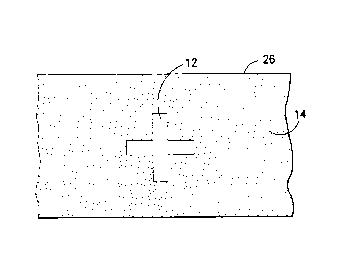
Figure 1 is a diagrammatic view of a textile fabric which has
5 been coated with a conductive polymer of the kind disclosed
hereinbelow, wherein a cross-shaped portion of the conductive coating
has been removed in a pattern configuration;
Figure 2 is a diagrammatic view of a coated fabric where the
conductive coating has been selectively removed in a repeating
10 geometrical shape of decreasing size, thereby forming a pattern in
which the unit electrical conductivity of the fabric varies along its
length (i.e., left to right);
- Figure 3 is a diagrammatic view of a coated fabric in which the
conductive coating has been selectively removed in a repeating
15 geometrical pattern which provides for a change in conductivity across
the width of the fabric (i.e., in an up and down direction, as shown);
Figure 4 is a diagrammatic view of a coated fabric in which the
conductive coating has been selectively but gradually removed along a
strip, thereby forming a conductive coating which forms a conductivity
20 gradient in the direction of the strip.
Figure 4A shows a fabric in which a strip similar to that of
Figure 4 extends across the width of the fabric;
Figure 5 is a diagrammatic view of a composite structure
comprised of several layers of fabric, each of which has been coated
25 with the conductive coating disclosed herein, and each of which has
had various portions of that coating removed to form a non-uniform
conductive coating;
Figure 5A is a side view of various sections of a pile textile
substrate where the pile, coated with a conductive polymer, has been
30 non-uniformly sheared, resulting in a substrate which exhibits non-
uniform electrical conductivity perpendicular to the substrate base;
Figures 6A, 6B, and 6C are light photomicrographs at respective
powers of 70X, 210X, and 430X, showing a cross section taken in the
fill direction (i.e., warp yarns viewed end-on) of a coated but
35 untreated woven fabric sample coating;
Figures 7A, 7B, and 7C are light photomicrographs, corresponding
to those in Figures 6A through 6C, showing the results of treatment
using a high velocity water jet apparatus as disclosed herein;
Figures 8A, 8B, and 8C are light photomicrographs at respective
40 powers of 70X, 210X, and 430X, showing a cross section taken in the
warp direction (i.e., fill yarns viewed end-on) of a coated but
untreated woven fabric sample;
Figures 9A, 9B, and 9C are light photomicrographs, corresponding
to those in Figures 8A through 8C, showing the results of treatment
W O 91/08896 P ~ /US90/07200
-
- 20~613
using a high velocity water jet apparatus as disclosed herein;
Figure 10 is an overview of one apparatus which can be used to
remove the conductive coating from the textile substrates discussed
herein;
Figure 11 is a perspective view of the high pressure manifold
assembly depicted in Figure 10;
Figure 12 is a side view of the assembly of Figure 11;
Figure 13 is a cross-section view of the assembly of Figure 11,
showing the path of the high velocity fluid through the manifold, and
10 the path of the resulting fluid stream as it strikes a substrate
placed against the support roll;
Figure 14 depicts a portion of the view of Figure 13, but
wherein the fluid stream is prevented from striking the target
substrate by the deflecting action of a stream of control fluid;
Figure 15 is an enlarged, cross-section view of the encircled
portion of Figure 14;
Figure 16 is a cross-section view taken along lines XVI--X~I of
Figure 15, depicting the deflection of selected working fluid jets by
the flow of control fluid.
20 Best Mode for Carrying Out the Invention
As can be seen in Figure 1, the present invention makes possible
a fabric which carries a conductive coating substantially intact in
areas where relatively high electrical surface conductivity is
desired, and areas where the coating has been at least partially
25 removed and relatively low surface conductivity is desired. Cross 12
is the area on textile fabric 26 where a conductive polymer coating
has been removed, e.g., by means of contact with high velocity water
jets as disclosed hereinbelow. Background area 14 has been left
undisturbed. If fabric 26 is woven, treatment by water jets as
30 disclosed herein will result in the conductive coating being removed
preferentially from yarns parallel to the direction of substrate
travel through the machine. Accordingly, if fabric 26 is woven and is
passed through the water jets in the warp direction, more coating will
be displaced from the warp yarns, resulting in a substantially lower
35 conductivity in the warp direction within cross 12, as compared with
the fill direction within cross 12 (assuming little or no initial
conductivity directionality prior to treatment). It is a
characteristic of this process that the coating is preferentially (but
not exclusively) removed fro~ those fibers which form the exposed
40 surface portions of the fabric surface.
In Figures 2 and 3, the conductive polymeric coating on fabric
26A has been at least partially removed in the areas indicated at 16
and 18, respectively, resulting in reduced electrical conductivity in
those areas, at least in certain directions. The fabric shown in
W O 9l/08896 P ~ /US90/07200
2 0 4 S 6~ 1 3
Figure 2 will have an average, per square conductivity gradient, the
conductivity increasing from left to right. In Figure 3, a gradient
of decreasing average, per square conductivity extends from top to
bottom. It should be understood that within each treated area 16,18,
5 the conductivity may also exhibit a directional nature if the fabric
is woven and the coating removal technique is the water jet treatment
discussed herein. Therefore, the fabric may exhibit both local and
overall anisotropy (i.e., directional conductivity).
As discussed above, if the fabric 26A of Figures 2 and 3 is a
10 woven fabric and the coating displacement technique uses high velocity
water jets as disclosed herein, then the decrease in electrical
conductivity of the fabric within each of the treated square areas
will be greater in the same direction in which the jets moved over the
fabric, than in the transverse direction. It is believed the
15 direction characteristics with respect to warp and fill directions is
due at least in part to a tendency for the woven fabric yarns which
are transverse to the direction of fabric travel to "flip" quickly
through the direct path of the jets, while the yarns parallel to the
direction of fabric travel cannot move (which would thereby reduce
20 their exposure to the jets), and so receive more extended exposure to
the jets. By turning the fabric ninety degrees and moving the fabric
through the apparatus so the jets travel along the fabric in the fill
direction, the conductive coating can be removed preferentially in the
fill direction, resulting in a fabric which, if previously isotropic
in conductivity, will be more electrically conductive in the warp
direction than in the fill direction.
Figures 4 and 4A depict fabrics 26B in which the conductive
polymer coating has been displaced on the fabric respective in areas
20,21 in the form of a continuous gradient, i.e., the amount of
30 coating removal is varied gradually from one end of the strip to the
other by controlling the extent or turation of treatment. The extent
of coating removal may be linear, or may be in accordance with a
mathematical function, e.g., quadratic, step function, etc. If
fabrics 26B are woven fabrics with initially isotropic conductivity
35 characteristics and the coating has been removed in accordance with a
gradient pattern using high velocity water streams as disclosed
herein, then the electrical conductivity within respective areas 20,21
will change with the direction of measurement due to the direction-
preferential coating displacement characteristics discussed above.
40 The conductivity reduction will be highest in the direction parallel
to the direction of treatment. Additionally, the "per square"
conductivity will also change gradually in the direction of treatment
within respective areas 20,21. In Figure 4, the "per square"
conductivity gradient is shown extending along the length of the
W O 91/08896 P ~ /US90/07200
-
7 20~613
fabric web, whereas in Figure 4A, the "per square" gradient is
depicted as extending across the width of the fabric web.
Figure 5 depicts a composite arrangement comprised of a
plurality of individual sections of coated fabric 27A, 27B, 27C, and
5 27D, each of which carries a series of strips in which the
electrically conductive polymer has been at least partially removed.
As shown, the degree to which the polymer is removed may vary in the
same relative area on different levels of the composite, resulting in
a conductivity gradient which, as depicted, extends vertically through
10 the various layers of fabric. It is contemplated that the
individually displaced areas can be either vertically aligned, as
shown, or unaligned, depending upon the intended application. It is
also contemplated that any suitable individual pattern, such as, for
example, the patterns depicted in Figures 1 through 4A, may be placed
15 on some or all of the individual layers comprising the composite
structure of Figure 5. Accordingly, conductivity gradients which
extend in two or three directions are contemplated. It should be
noted that the various sections of fabric 27 A-D need not be
individually cut, but could be different portions of the same
20 continuous web, which web has been wrapped or layered about a form.
As discussed above, the individually treated areas may be aligned or
unaligned.
Figure 5A shows a pile fabric or carpet in which the conductive
coating has been applied to both the pile and the base. The pile
25 height has then been varied, as by shearing or other appropriate
method, to remove both pile yarns and their conductive coating. The
result is a substrate which exhibits a vertical conductivity gradient.
Figures 6A and 7A are optical photomicrographs showing the yarns
comprising a woven textile fabric which has been coated with the
30 conductive polymer disclosed herein, as seen at 70X magnification.
Individual filaments of warp yarns are shown extending out of the
page. As best seen in Figures 6B and 6C, almost all individual warp
yarns show a heavy dark outline, which is believed to be the
conductive polymeric coating. The coating completely covers the
35 perimeter of most of the individual warp yarn filaments. The coating
is believed to coat and surround large portions of the circumference
of those filaments, and to form an electrically conductive path,
perhaps along the entire length of some individual filaments. The
close physical proximity of partially coated filaments is thought to
40 promote electrical conduction between coated portions of continuous
adjacent filaments. Figures 7B and 7C, show a portion of the same
fabric of Figure 6, but which has been treated, in the warp direction,
with the high velocity water treatment disclosed. It is clear that
many of the individual filaments comprising the warp yarns have been
W O 91/08896 PCT/US90/07200
20~5613
partially stripped of their coating of the conductive polymer coating,
with the result that these yarns are less conductive along their
length than those yarns in which the coating has been undisturbed.
Warp filaments on the surface of the yarn bundle appear to have little
5 or no remaining coating. The coating on the warp filaments near the
center of the yarn bundle has been displaced and perhaps removed, but
not to the same degree. Some portions of the perimeter of the
individual filaments near the center of the yarn bundle have been
stripped of the conductive polymer, while the coating remains in other
10 areas of the same filament. The overall effect is to decrease the
conductivity of the fabric in the warp direction.
Looking at corresponding photomicrographs of the fill yarns, as
shown in Figures 8A, 8B, and 8C (untreated) and Figures 9A, 9B, and 9C
(treated), the degree to which the treatment is able to strip the
15 polymer coating from the individual yarn filaments is substantially
less than in the warp yarn case. As shown, the filaments comprising
the fill yarns are relatively unaffected by exposure to the high
velocity water jets, and remain substantially coated by the conductive
polymer, at least near the perimeter of the fill yarn bundle.
20 Similar conclusions are reached if, rather than inspecting the "end-
on" cross-sections of Figures 6 through 9, the filament profiles shown
near the bottom of the lower power photomicrographs are used for
comparison.
A consequence of this selective removal of the coating in woven
25 fabrics (i.e., primarily from yarns and filaments which extend
parallel to the direction in which the fabric is passed through the
high velocity water jet) is that the resulting fabric exhibits
electrical conductivity which is directional, i.e., is anisotropic,
and which favors conduction-in the fill direction (assuming the fabric
30 was initially isotropic and has been subjected to high velocity water
treatment while moving in the warp direction). Therefore, a woven
fabric treated in accordance with the te~chingc herein can be made to
be relatively electrically conductive (e.g., twenty ohms or less) in
the fill direction while, in the same area, exhibiting an electrical
35 conductivity substantially higher (e.g., several tens of thousand
ohms) in the warp direction.
As discussed further below, the water jet process used to
produce this nonuniformly conductive woven fabric can also be used on
fabric having other constructions, for example, knitted or non-woven
40 fabrics. However, when fabrics other than woven fabrics are used, the
coating removal process results in fabrics exhibiting substantially
isotropic electrical resistance or impedance within a given uniformly
treated area. To achieve overall anisotropic conductivity using these
fabrics, the fabric must either carry a pattern in which the
WO gl/08896 PCr/US90/0720~
9 2U~5613
conduct~ve polymer is removed to a greater or lesser extent within a
given treated rea (e.g., as shown in Figures 4 ~nd 4A), or the
treated area mus~ be in the form of a pattern wh~ch results in the
desiret average conductivity characteristics (8S in Figures 1-3).
5 This can be achieved by selective removal of the coatin~ in a desired
pattern configuration, either by water ~et treatment, sculpturing
techniques, or other appropr$ate means.
It can therefore be appreciated that the invention disclosed
herein may be used on any suitable fabric, regardless of construction,
10 to form one or more conductive paths over the fabric's
surface. It can therefore be appreciated that the
invention disclosed herein may be used on any suitable
fabric, regardless of construction, to form one or more
conductive paths over the fabric's surface. As discussed
15 previously, woven fabrics are described in terms of "warp"
and "fill". ~he "warp" direction is the direction of the
yarns in all woven fabrics that runs lengthwise and
parallel to the selvage and is interwoven with the
filling. The "fill" direction in woven fabrics is the
20 yarn running from selvage to selvage at right angles to
the warp. A yarn is composed of fibers. A knit fabric
comprises an interlocking series of loops of one or more
yarns. There are two major types of knitting. There is
warp knitting in which the yarns generally run lengthwise
25 in the fabric. The yarns are prepared on beams with one
or more yarns for each needle. Examples of this type of
knitting are tricot, milanese, and raschel knitting. The
other type of knitting is weft knitting in which one
continuous thread runs crosswise in the fabric making all
30 the loops in one course. Examples of weft knitting are
circular and flat knitting. Knitting is described in
terms of "wales" and "courses". A "wale" is defined as a
column of loops of yarn lying lengthwise in the fabric and
- a "wale" direction is the direction of the columns of
loops of yarns lying lengthwise in the fabric. The number
of wales per inch is a measure of fineness in the fabric.
A "wale" corresponds to the term "warp" in knitted fabric.
~,.
ga 2045613
For both woven and knitted fabrics, these terms refer to
the yarns that run lengthwise in the fabric and when this
disclosure refers to the two directions of the fabric,
this is to be considered one of them. The term "course"
for knitted fabrics corresponds to the term "fill" in
woven fabrics and describes the row of loops or stitches
running across a knit fabric and a "course" direction is
the direction of the row of loops or stitches running
across the fabric. This is considered the second
direction of the fabric. A nonwoven fabric is defined as
an assembly of textile fibers held together by me~nical
interlocking in a random web or mat, but fusing of the
fibers (in the case of thermoplastic ~ibers), or by
bonding with a cementing medium such as starch, glue,
casein, rubber, latex, or one of the cellulose derivatives
or synthetic resins. Initially, the fibers may be
oriented in one direction or may be deposited in a random
manner. This web or sheet is bonded together by one of
the methods described above. One of the two directions of
this fabric is that of a "vertical" direction which
corresponds to the "warp" direction in woven fabrics and
to the "wale" direction in knit fabrics. This "vertical"
direction also runs lengthwise in the fabric. The
remaining direction is that of a "horizontal" direction
which corresponds to the "fill" direction in woven fabrics
and to the "course" direction in knit fabrics. This
"horizontal" direction also runs crosswise in the fabric.
It is respectfully believed that the applicant's invention
is applicable to any type of fabric. If
non-unlformity (i.e., dep~ t upon the direction of current flow) is
desired in other than woven fabrics, that characteristic $s preferably
achieved through choice of pattern or severity of treatment (e.g.,
water velocity, residence time under the jet, etc.). As explained
above, woven fabrics may posess a resistance or impedence
directionality as a consequence of their construction, as well as by
treatment using water ~ets. When such fabric variations are combined
..~
- 9b - 20~61~
with choice of pattern, and/or severity of treatment, it is possible
to protuce a wide variety of fabrics having rather complex resistance
or impedence characteristics.
The following discussion will address the preferred method by
which the coating is displacet selectively in a pattern configurstion
to form a woven fabric having nonuniform ant anisotropic electrical
conductivity characteristics. None of the methods or compositions
disclosed for generating a conductive coating are intended to be a
part of the invention claimed herein.
The process for generating the conductive coating used herein,
which process is more completely discussed in U.S. Patent No.
4,803,096 to Kuhn, et al., involves the substrate being treated with
the polymerizable ~ nd and oxidizing gent at relatively dilute
concentrations and under conditions which do not result in either the
monomer or the oxidizing agent being taken up, whether by adsorption,
impregnation, absorption, or otherwise, by the preformed fabric (or
the fibers, filaments or yarns forming the fabric). Rather, the
polymerizable monomer and oxidizing reagent will first react with each
other to form a ~pre-polymer" species, th- exact nature of which has
not yet been fully ascertained, but which may be a water-soluble or
dispersible free radical-ion of the compound, or a water-soluble or
dispersible dimer or oligomer of the polymerizable compound, or some
other unidentified ~pre-polymer~ species. In any case, it is the ~pre-
polymer" species, i.e. the fn sratus n~scendi forming polymer, which
is epitsxially teposited onto the surface of the individual fibers or
filaments, as such, or as a component of yarn or preformed fabric or
other textile material. Thus, process conditions, such as reaction
,~
r ~
W O 91/08896 P~r/US90/07200
-
204~613 `-
-10-
temperature, concentration of reactants and textile material, and
other process conditions are controlled so as to result in epitaxial
deposieion of the pre-polymer particles being formed in the in status
nascendi phase, that is, as they are being formed. This results in a
5 very uniform film being formed at the surface of individual fibers or
filaments without any significant formation of polymer in solution and
also results in optimum usage of the polymerizable compound so thst
even with a relatively low amount of pyrrole or aniline applied to the
surface of the textile, nonetheless a relatively high amount of
10 conductivity is capable of being achieved.
As mentioned briefly above it is the in status nascendi forming
compound that is epitaxially deposited onto the surface of the textile
material. As used herein the phrase "epitaxially deposited" means
deposition of a uniform, smooth, coherent and "ordered" film. This
15 epitaxial deposition phen~ -nOQ may be said to be related to, or a
species of, the more conventionally understood adsorption phen~_?nsn.
While the adsorption phen~ - -n is not ~cessArily a well known
phe enoll in terms of textile finishin~ operations it certainly has
been known that monomeric materials may be adsorbed to many substrates
including textile fabrics. The adsorption of polymeric materials from
the liquid phase onto a solid surface is a phg - - -- which is known,
to some extent, especially in the field of biological chemistry. For
example, reference is made to U.S. Patent 3,909,195 to Machell, et al.
and U.S. Patent 3,950,589 to Togo, et al. which show methods for
treating textile fibers with polymerizable compositions, although not
in the context of electrically conductive fibers.
Epitaxial deposition of the in status nascendi forming pre-
polymer of either pyrrole or aniline is caused to occur, by, among
other factors, controlling the type and concentration of polymerizable
30 compound in the aqueous reaction medium. If the co~centration of
polymerizable compound (relative to the textile material and/or
aqueous phase) is too high, polymerization may occur virtually
instantaneously both in solution and on the surfsce of the textile
material and a black powder, e.g. ~black pol~L.olen, will be formed
35 and settle on the bottom of the reaction flask. If, however, the
concentration of polymerizabLe c~ , in the aqueous phase and
relative to the textile material, is maintained at relatively low
levels, for instance, depen~{nt on the particular oxidizing agent,
from about .01 to about 5 grams of polymerizable compound per 50 grams
40 of textile material in one liter of aqueous solution, preferably from
about 1.5 to about 2.5 grams polymerizable compound per 50 grams
textile per liter, polymerization occurs at a sufficiently slow rate,
and the pre-polymer species will be epitaxially deposited onto the
textile material before polymerization is completed. Reaction rates
~. l
W O 91/08896 PCT/US90/07200
20~613
may be further controlled by variations in other reaction conditions
such as reaction temperatures, etc. and other additives. This rate is,
in fact, sufficiently slow that it may take several minutes, for
example 2 to 5 minutes or longer, until a significant change in the
5 appearance of the reaction solution is observed. If a textile material
is present in this in status nascendi forming solution of pre-polymer,
the forming species, while still in solution, or in colloidal
suspension will be epitaxially deposited onto the surface of the
textile material and a uniformly coated textile material having a
lO thin, coherent, and ordered conductive polymer film on its surface
will be obtained.
In general, the amount of textile material per liter of aqueous
liquor may be from about 1 to 5 to 1 to 50 preferably from about 1 to
lO to about 1 to 20.
Controlling the rate of the in status n~scendi forming polymer
deposition epitaxially on the surface of the fibers in the textile
material is not only of importance for controlling the reaction
conditions to optimize yield and proper formation of the polymer on
the surface of the individual fiber but foremost influences the
20 molecular weight and order of the epitaxially deposited polymer.
Higher molecular weight and higher order in electrically conductive
polymers imparts higher conductivity and most importantly higher
stability to these products.
Pyrrole is the preferred pyrrole monomer, both in terms of the
25 conductivity of the doped polypyrrole films and for its reactivity.
However, other pyrrole monomers, including N-methylpyrrole, 3-
methylpyrrole, 3,5-dimethylpyrrole, 2,2-bipyrrole, and the like,
especially N-methylpyrrole can also be used. More generally, the
pyrrole compound may be selected from pyrrole, 3-, and 3,4-alkyl and
30 aryl substituted pyrrole, and N-alkyl, and N-aryl pyrrole. In
addition, two or more pyrrole monomers can be used to form conductive
copolymer, especially those containine pre~. in~ntly pyrrole,
especially at least 50 mole percent, preferably at least 70 mole
percent, and especially preferably at least 90 mole percent of
35 pyrrole. In fact, the addition of a pyrrole derivative as comonomer
having a lower polymerization reaction rate than pyrrole may be used
to effectively lower the overall polymerization rate. Use of other
pyrrole monomers, is, however, not preferred, particularly when
especially low resistivity is desired, for example, below about 1,000
40 ohms per square.
In addition to pyrrole compounds, it has been found that aniline
under proper conditions can form a conductive film on the surface of
textiles much like the pyrrole compounds mentioned above. Aniline is a
very desirable monomer to be used in this expitaxial deposition of an
W O 91/08896 PCT/US90/07200
-12- 20~5613
in status nascendi forming polymer, not only for its low cost, but
also because of the excellent stability of the conductive polyaniline
formed.
Any of the known oxidizing agents for promoting the
5 polymerization of polymerizable monomers may be used in this
invention, including, for example, the chemical oxidants and the
chemical compounds contAinin~ a metal ion which is capable of changing
its valence, which compounds are capable, during the polymerization of
the polymerizable compound, of providing electrically conductive
10 polymers, including those listed in U.S. Patent Nos. 4,604,427 to
Roberts, et al., 4,521,450 to Bjorklund, et al. and 4,617,228 to
Newman, et al.
Specifically, suitable chemical oxidants include, for instance,
compounds of polyvalent metal ions, such as, for example, FeCl3,
15 Fe2(SO4)3, K3(Fe(CN)6), H3PO4.12MoO3, H3PO4.12WO3, CrO3, (NH4)2Ce(NO3)6,
CuCl2, AgNO3, etc., especially FeCl3, and compounds not containing
polyvalent metal compounds, such as nitrites, quinones, pçroxides,
peracids, persulfates, perborates, peL qneAnAteS~ perchlorates,
chromates, and the like. Examples of such non-metallic type of
20 oxidants include, for example, HNO3, 1,4-benzoquinone, tetrachloro-l,
4-benzoquinone, hydrogen peroxide, peroxyacetic acid, peroxybenzoic
acid, 3-chloroperoxybenzoic acid, ammonium persulfate, ammonium
perborate, etc. The alkali metal salts, such as sodium, potassium or
lithium salts of these compounds, can also be used.
In the case of aniline, as is true with pyrrole, a great number
of oxidants may be suitable for the production of conductive fabrics,
this is not necessarily the case for aniline. Aniline is known to
polymerize to form at least five different forms of polyaniline, most
of which are not conductive. At the present time the emeraldine form
30 of polyaniline as described by Uu-Song Huang, et al., is the preferred
species of polyaniline. As the name implies, the color of this species
of polyaniline is green in contrast to the black color of polypyrrole.
With regard to aniline the concentration in the aqueous solution may
be from about 0.02 to 10 grams per liter. Aniline compounds that may
35 be employed include in addition to aniline per se, various substituted
anilines such as halogen substituted, e.g. chloro-or bromo-
substituted, as well as alkyl or aryl-substituted anilines.
The suitable chemical oxidants for the polymerization include
persulfates, particular ammonium persulfate, but conductive textiles
40 could also be obtained with ferric chloride. Other oxidants form
polyaniline films on the surface of the fibers such as, for instance,
potassium dichromate and others.
When employing one of these non-metallic chemical oxidants for
promoting the polymerization of the polymerizable compound, it is also
W O 91/08896 P ~ /US90/07200
-
-13- - ~045~1~
preferred to include a "doping" agent or counter ion since it is only
the doped polymer film that is conductive. For these polymers, anionic
counter ions, such as iodine chloride and perchlorate, provided by,
for example, I2, HCl, HC104, and their salts and so on, can be used.
5 Other suitable anionic counter ions include, for example, sulfate,
bisulfate, sulfonate, sulfonic acid, fluoroborate, PF6-, AsF6-, and
SbF6~and can be derived from the free acids, or soluble salts of such
acids, including inorganic and organic acids and salts thereof.
Furthermore, as is well known, certain oxidants, such as ferric
10 chloride, ferric perchlorate, cupric fluoroborate, and others, can
provide the oxidant function and also supply the anionic counter ion.
However, if the oxidizing agent is itself an anionic counter ion it
may be desirable to use one or more other doping agents in conjunction
with the oxidizing agent.
Especially good conductivity can be achieved using sulfonic acid
derivatives as the counter ion dopant for the polymers. For example,
mention can be made of the aliphatic and aromatic sulfonic acids,
substituted aromatic and aliphatic sulfonic acids as well as-polymeric
sulfonic acids such as poly (vinylsulfonic acid) or poly
(styrenesulfonic acid). The aromatic sulfonic acids, such as, for
example, benzenesulfonic acid, para-toluenesulfonic acid p-
chlorobenzenesulfonic acid and naphthalenedisulfonic acid, are
preferred. When these sulfonic acid compounds are used in conjunction
with, for example, hydrogen peroxide, or one of the other non-metallic
25 chemical oxidants, in addition to high conductivity of the resulting
polymer films, there is a further advantage that the reaction can be
carried out in conventional stainless steel vessels. In contrast,
FeCl3 oxidant is highly corrosive to stainless steel and requires
glass or other expensive specialty metal vessels or lined vessels.
30 Moreover, the peroxides, persulfates, etc. have higher oxidizing
potential than FeCl3 and can increase the rate of polymerization of
the compound.
Generally, the amount of oxidant is a controlling factor in the
polymerization rate and the total amount of oxidant should be at least
35 equimolar to the amount of the monomer. However, it may be useful to
use a higher or lower amount of the chemical oxidant to control the
rate of polymerization or to assure effective utilization of the
polymerizable monomer. On the other hand, where the chemical oxidant
also provides the counter ion dopant, such as in the case with FeCl3,
40 the amount of oxidant may be substantially greater, for example, a
molar ratio of oxidant to polymerizable compound of from about 4:1 to
about 1:1, preferably 3:1 to 2:1.
Within the amounts of polymerizable compound and oxidizing agent
as described above, the conductive polymer is formed on the fabric in
W O 91/08896 P ~ /US90/07200
2045613 -14-
amounts corresponding to about 0.5% to about 4%, preferably about l.0
to about 3%, especially preferably about l.5% to about 2.5%, such as
about 2%, by weight based on the weight of the fabric. Thus, for
example, for a fabric weighing lO0 grams a polymer film of about 2 gm
5 may typically be formed on the fabric.
Furthermore, the rate of polymerization of the polymerizable
compound can be controlled by variations of the pH of the aqueous
reaction mixture. While solutions of ferric chloride are inherently
acidic, increased acidity can be conveniently provided by acids such
lO as HCl or H2S0~; or acidity can be provided by the doping agent or
counter ion, such as benzenesulfonic acid and its derivatives and the
like. It has been found that pH conditions from about five to about
one provide sufficient acidity to allow the in status nascendi
epitaxial adsorption of the polymerizable compound to proceed.
15 Preferred conditions, however, are encountered at a pH of from about
three to about one.
Another important factor in controlling the rate of
polymerization (and hence formation of the pre-polymer adsorbed
species) is the reaction temperature. As is generally the case with
20 chemical reactions, the polymerization rate will increase with
increasing temperature and will decrease with decreasing temperature.
For practical reasons it is convenient to operate at or near ambient
temperature, such as from about 10C to 30C, preferably from about
18C to 25C. At temperatures higher than about 30C, for instance at
25 about 40C or higher, the polymerization rate becomes too high and
exceeds the rate of epitaxial deposition of the in status nascendi
forming polymer and also results in production of unwanted oxidation
by-products. At temperatures below about 10C, the polymerization rate
- becomes slower but a higher degree of order and therefore better
30 conductivities can be abtained. The polymerization of the
polymerizable compound can be performed at temperatures as low as
about 0C (the freezing temperature of the aqueous reaction media) or
even lower where freezing point depressants, such as various
electrolytes, including the metallic compound oxidants and doping
35 agents, are present in the reaction system. The polymerization
reaction must, of course, take place at a temperature above the
freezing point of the aqueous reaction medium so that the prepolymer
species can be epitaxially deposited onto the textile material from
the aqueous reaction medium.
Yet another controllable factor which has significance with
regard to the process of the present invention is the rate of
deposition of the in status nascendi forming polymer on the textile
material. The rate of deposition of the polymer to the textile fabric
should be such that the in status nascendi forming polymer is taken
W O 91/08896 P ~ /US90/07200
-
204~613
-15-
out of solution and deposited onto the textile fabric as quickly as it
is formed. If, in this regard, the polymer or pre-polymer species is
allowed to remain in solution too long, its molecular weight may
become so high that it may not be efficiently deposited but, instead,
5 will form a black powder which will precipitate to the bottom of the
reaction medium.
The rate of epitaxial deposition onto the textile fabric
depends, inter alia, upon the concentration of the species being
deposited and also depends to some degree on the physical and other
10 surface characteristics of the textile material being treated. The
rate of deposition, furthermore, does not necessarily increase as
concentrations of the polymeric or pre-polymer material in the
solution increase. On the contrary, the rate of epitaxial deposition
of the in status nascendi forming polymer material to a solid
15 substrate in a liquid may actually increase as concentration of the
material increases to a maximum and then as the concentration of the
material increases further the rate of epitaxial deposition may
actually decrease as the interaction of the material with itself to
make higher molecular weight materials becomes the controlling factor.
Deposition rates and polymerization rates may be influenced by
still other factors. For instance, the presence of surface active
agents or other monomeric or polymeric materials in the reaction
medium may interfere with and/or slow down the polymerization rate. It
has been observed, for example, that the presence of even small
25 quantities of nonionic and cationic surface active agents almost
completely inhibit formation on the textile material of the
electrically conductive polymer whereas anionic surfactants, in small
quantities, do not interfere with film formation or may even promote
formation of the electrically conductive polymer film. With regard to
30 deposition rate, the addition of electrolytes, such as sodium
chloride, calcium chloride, etc. may enhance the rate of deposition.
The deposition rate also depends on the driving force of the
difference between the concentration of the adsorbed species on the
surface of the textile material and the concentration of the species
35 in the liquid phase exposed to the textile material. This difference
in concentration and the deposition rate also depend on such factors
as the available surface area of the textile material exposed to the
liquid phase and the rate of replenishment of the in status nascendi
forming polymer in the vicinity of the surfaces of the textile
40 material available for deposition.
Therefore, it follows that best results in forming uniform
coherent conductive polymer films on the textile material are achieved
by continuously agitating the reaction system in which the textile
material is in contact during the entire polymerization reaction. Such
W O 91/08896 P ~ /US90/07200
i 0 ~5 6 ~ 3 -16-
agitation can be provided by simply shaking or vibrating or tumbling
the reaction vessel in which the textile material is immersed in the
liquid reactant system or alternatively, the liquid reactant system
can be caused to flow through and/or across the textile material.
As an example of this later mode of operation, it is feasible to
force the liquid reaction system over and through a spool or bobbin of
wound textile filaments, fibers (e.g. spun fibers), yarn or fabrics,
the degree of force applied to the liquid being dependent on the
winding density, a more tightly wound and thicker product requiring a
10 greater force to penetrate through the textile and uniformly contact
the entire surface of all of the fibers or filaments or yarn.
Conversely, for a loosely wound or thinner yarn or filament package,
correspondingly less force need be applied to the liquid to cause
uniform contact and deposition. In either case, the liquid can be
15 recirculated to the textile material as is customary in many types of
textile treating processes. Yarn packages up to 10 inches in diameter
have been treated by the process of this invention to provide uniform,
coherent, smooth polymer films. The observation that no particulate
matter is present in the coated conductive yarn package provides
20 further evidence that it is not the polymer particles, per se which
are water-insoluble and which, if present, would be filtered out of
the liquid by the yarn package - that are being deposited onto the
textile material.
As an indication that the polymerization parameters, such as
25 reactant concentrations, temperature, and so on, are being properly
maintained, such that the rate of epitaxial deposition of the in
status n~scendi forming polymer is sufficiently high that polymer does
not accumulate in the aqueous liquid phase, the liquid phase should
-: remain clear or at least substantially free of particles visible to
30 the naked eye throughout the polymerization reaction. Yields of
pyrrole polymer, for instance, based on pyrrole monomer, of greater
than 50%, especially greater than 75~, can be achieved.
When the process disclosed herein is applied to textile fibers,
filaments or yarns directly, whether by the above-described method for
35 treating a wound product, or by simply passing the textile material
through a bath of the liquid reactant system until a coherent uniform
conductive polymer film is formed, or by any other suitable technique,
the resulting composite electrically conductive fibers, filaments,
yarns, etc. remain highly flexible and can be subjected to any of the
40 conventional knitting, weaving or similar techniques for forming
fabric materials of any desired shape or configuration, without
impairing the electrical conductivity.
Furthermore, the rate of oxidative polymerization can be
effectively controlled to a sufficiently low rate to obtain desirably
W O 91/08896 P ~ /US90/07200
-
204561 3
-17-
ordered polymer films of high molecular weight to achieve increased
stability, for instance against oxidative degradation in air. Thus, as
described above, reaction rates can be lowered by lowering the
reaction temperature, by lowering reactant concentrations (e.g. using
S less polymerizable compound, or more liquid, or more fabric), by using
different oxidizing agents, by increasing the pH, or by incorporating
additives in the reaction system.
While the precise identity of the adsorbing species has not been
identified with any specificity, certain theories or ?chAnisms have
10 been advanced although the invention is not to be considered to be
limited to such theories or proposed mechanisms. It has thus been
suggested that in the chemical or electrochemical polymerization, the
monomer goes through a cationic, free radical ion stage and it is
possible that this species is the species which is adsorbed to the
15 surface of the textile fabric. Alternatively, it may be possible that
oligomers or pre-polymers of the monomers are the species which are
deposited onto the surface of the textile fabric. In the case of the
oxidative polymerization of aniline a similar mechanism to the
polymerization of pyrrole may occur. It is believed that in the case
20 of polyaniline formation, a free radical ion is also formed as a
prepolymer and may be the species which is actually adsorbed.
In any event, if the rate of deposition is controlled as
described above, it can be seen by microscopic investigation that a-
uniform and coherent film of polymer is deposited onto the surface of
25 the textile material. Analyzing this film, by dissolving the fibers of
the textile fabric from under the composite, washing the residual
polymer with additional solvent and then eY~ jning the resulting array
with a light microscope, shows that the film is actually in the form
of burst tubes, thus evidencing the uniformity of the formed
30 electrically conductive film. Surprisingly, each film or fragment of
film is quite uniform. The films are either transparent or semi-
transparent because the films are, in general, quite thin and one can
directly conclude from the intensity of the color observed under the
microscope the relative thickness of the film. In this regard, it has
35 been calculated that film thickness may range from about 0.05 to about
2 microns, preferably from 0.1 to about 1 micron. Further, microscopic
examination of the films show that the surface of the films is quite
smooth. This is quite surprising when one contrasts these films to
polypyrrole formed electrochemically or chemically, wherein,
40 typically, discrete particles may be found within or among the
polymeric films.
A wide variety of textile materials may be employed, for
- example, fibers, filaments, yarns and various fabrics made therefro~.
Such fabrics may be woven or knitted fabrics and are preferably based
W O 91/08896 P ~ /US90/07200
a~4S,,6l3
-18-
on synthetic fibers, filaments or yarns. In addition, even non-woven
structures, such as felts or similar materials, may be employed.
Preferably, the polymer should be epitaxially deposited onto the
entire surface of the textile. This result may be achieved, for
instance, by the use of a relatively loosely woven or knitted fabric
but, by contrast, may be relatively difficult to achieve if~ for
instance, a highly twisted thick yarn were to be used in the
fabrication of the textile fabric. The penetration of the reaction
medium through the entire textile material is, furthermore, enhanced
10 if, for instance, the fibers used in the process are texturized
textile fibers.
Fabrics prepared from spun fiber yarns as well as continuous
filament yarns may be employed. In order to obtain optimum
conductivity of a textile fabric, however, it may be desirable to use
15 continuous filament yarns so that a film structure suitable for the
conducting of electricity runs virtually continuously over the entire
surface of the fabric. In this regard, it has been observed, as would
be expected, that fabrics produced from spun fibers processed
according to the present invention typically show somewhat less
20 conductivity than fabrics produced from continuous filament yarns.
A wide variety of synthetic fibers may be used to make the
textile fabrics of the present invention. Thus, for instance, fabric
made from synthetic yarn, such as polyester, nylon and acrylic yarns,
may be conveniently employed. Blends of synthetic and natural fibers
25 may also be used, for example, blends with cotton, wool and other
natural fibers may be employed. The preferred fibers are polyester,
e.g. polyethylene terephthalate including cationic dyeable polyester
and polyamides, e.g. nylon, such as Nylon 6, Nylon 6,6, and so on.
Another category of preferred fibers are the high modulus fibers such
30 as aromatic polyester, aromatic polyamide and polybenzimidazole. Still
another category of fibers that may be advantageously employed include
high modulus inorganic fibers such as glass and ceramic fibers.
Although it has not been clearly established, it is believed that the
sulfonate groups or amide groups present on these polymers may
35 function as a "built-in" doping agent.
Conductivity measurements have been made on the fabrics which
have been prepared according to the method of the present invention.
Standard test methods are available in the textile industry and, in
particular, M TCC test method 76-1982 is available and has been used
40 for the purpose of measuring the resistivity of textile fabrics.
According to this method, two parallel electrodes 2 inches long are
contacted with the fabric and placed 1 inch apart. Resistivity may
then be measured with a standard ohm meter capable of measuring values
between 1 ohm and 20 million ohms. Measurements must then be
W O 91/08896 P ~ /US90/07200
20~5~13
-19-
multiplied by 2 in order to obtain resistivity in ohms on a per square
basis. While conditioning of the samples may ordinarily be required to
specific relative humidity levels, it has been found that conditioning
of the samples made according to the present invention is not
5 necessary since conductivity measurements do not vary significantly at
different humidity levels. The measurements reported in the following
example are, however, conducted in a room which is set to a
temperature of 70F and 50~ relative humidity. Resistivity
measurements are reported herein and in the examples in ohms per
10 square ( /sq) and under these conditions the corresponding
conductivity is one divided by resistivity.
In general, fabrics treated according to the teachings herein
show resistivities of below 106 ohms per square, such as in the range
of from about 20 to 500,000 ohms per square, preferably from about 500
to S,000 ohms per square. These sheet resistivities can be converted
to volume resistivities by taking into consideration the weight and
thickness of the polymer films. Some samples tested after aging for
several months do not significantly change with regard to resistivity
during that period of time. In addition, samples heated in an oven to
20 380OF for about one minute also show no significant loss of
conductivity under these conditions. These results indicate that the
stability of the conductive film made on the surface of textile
materials is excellent, indicating a higher molecular weight and a
higher degree of order than usually obtained by the chemical oxidation
25 of these monomers.
Various procedures can be used to perform the method of
preparation of a conductive fabric as it applies to the invention by
operating within the parameters as described above. Typical methods
are described below:
Method A
- Approximately 50 g of fabric is placed in a dyeing ~chine
having a rotating basket insert and the port of the machine is closed.
Depending upon the desirable liquid ratio, usually about 500 cc, water
is then added to the reaction chamber. The basket is turned to assure
that the fabric is properly wetted out before any other ingredients
are added. Then the desired amount and type of oxidizing agent is
dissolved in approximately 500 cc of water and is added to the machine
while the basket is rotating. Finally, the monomer and if necessary
40 the doping agent in approximately 500 cc of water is added through the
addition tank to the rotating mixture. In order to eliminate any heat
build-up during the rotation, cooling water is turned on so that the
- temperature of the bath is kept at the temperature of the cooling
water, usually between 20 and 30C. After the fabric has been exposed
W O 91/OXX9~ PCT/US90/07200
2~5613
-20-
for the appropriate length of time, the bath is dropped and replaced
with water; in this way the fabric is rinsed twice. The fabric is then
withdrawn and air dried.
Method B
An 8 ounce jar is charged with five to ten grams of the fabric
to be treated. Generally, approximately 150 cc of total liquor are
used in the following manner: First, approximately 50 cc of water is
added to the jar and the jar is closed and the fabric is properly
10 wetted out with the initial water charge. The oxidizing agent is then
added in approximately 50 cc of water, the jar is closed and shaken
again to obtain an appropriate mixture. Then the monomer and if
necessary the doping agent in 50 cc of water is added at once to the
jar. The jar is first shaken by hand for a short period of time and
then is put in a rotating clamp and rotated at approximately 60 RPM
for the appropriate length of time. The fabric is withdrawn, rinsed
and air dried as described for Method A. Conveniently this method can
be used to conduct the reaction at room temperature or if preferred at
lower temperatures. If lower temperatures are used the mixture
20 including the fabric and oxidizing agent is first immersed into a
constant temperature bath such as a mixture of ice and water and
rotated in such a bath until the temperature of the mixture has
assumed the temperature of the bath. Concurrently the monomer and if
necessary the doping agent in water is also precooled to the
25 temperature at which the experiment is to be conducted. The two
mixtures are then combined and the experiment is continued, rotating
the reaction mixture in the constant temperature bath.
- Method C
A one-half gallon jar is charged with 50-100 g of fabric to
which usually a total of 1.5 liter of reaction mixture is added in the
following manner: First, 500 cc of water are added to the jar and the
fabric is properly wetted out by sh~king. Then the oxidizing agent
. dissolved in approximately 500 cc of water is added and mixed with the
35 original charge of water. Subsequently, the monomer and if necessary
the doping agent in 500 cc of water is added at once to the jar. The
jar is closed and set in a shaking -chine for the appropriate length
of time. The fabric is withdrawn from the jar and washed with water
and air dried.
Method D
A glass tube approximately 3 cm in diameter and 25 cm long
equipped with a removable top and bottom connection is charged with
approximately 5 to 10 g of fabric which has been carefully rolled up
-
W O 91/08896 P(~r/US90/07200
-21- 20~5613
to fill approximately 20 cm of the length of the tube. A mixture
containing approximately 150 cc of reaction mixture is prepared by
dissolving the oxidizing agent in approximately 100 cc of water and
then adding at once to the solution a mixture of the monomer and if
S necessary the doping agent in approximately 50 cc of water. The
resulting mixture of oxidizing agent and monomer is pumped into the
glass tube through the bottom inlet by the use of a peristaltic pump,
eg. from Cole Palmer. As soon as the entire amount is inside the glass
tube, the pump is momentarily stopped and the hose through which the
10 liquor has been sucked out of the container is connected to the top
outlet of the reaction chamber. The flow is then reversed and the
pumping action continues for the desired amount of time. After this,
t~e tube is emptied and the fabric is withdrawn from the tube and
rinsed in tap water.
In Method D the glsss tube can be jacketed and the reaction can
be run at temperatures which can be varied according to the
temperature of the circulating mixture in the ~acket.
These methods describe a number of possible modes by which this
reaction can be carried out.
Unless otherwise indicated, all parts and percentages are by
weight, and a reported conductivity measurements are in the warp
direction and fill directions, respectively, unless otherwise noted.
EXAMPT F 1
Following the procedure described for Method A, 50 grams of a
polyester fabric consisting of a 2x2 right hand twill, weighing
approximately 6.6 oz. per square yard and being constructed from a
2/150/34 textured polyester yarn from Celanese Type 667 (fabric
construction is such that approximately 70 ends are in the warp
30 direction and 55 picks are in the fill direction), is placed in a
Werner Mathis JF dyeing machine using 16.7 g ferric chloride
hexahydrate, 2 g of pyrrole, 1.5 g of 37% hydrochloric acid in a total
of 1.5 liters of water. The treatment is conducted at room temperature
conditions for two hours. The resulting fabric has a dark gray,
35 metallic color and a resistivity of 3,000 and 4,000 ohms per square in
the warp and fill directions, respectively.
EXAMPLE 2
Example 1 is repeated except that the fabric is made from basic
40 dyeable polyester made from DuPonts Dacron*92T is used in the same
construction as described in Example 1. The resistivity on the fabric
measures 2,000 ohms per square in the warp direction and 2,700 ohms
per square in the fill direction. This example demonstrates that the
presence of anionic sulfonic acid groups, as they are present in the
*Trade Mark
.~
W O 91/08896 PCT/US90/07200
204~561~
-22-
basic dyeable polyester fabric, apparently enhances the adsorption of
the polymerizing species to the fabric, resulting in a higher
conductivity.
EXAMPLE 3
Example 1 is repeated except that 50 g of nylon fabric,
constructed from an untextured continuous filament of Nylon 6, as
described in Style #322 by Test Fabrics, Inc. of Middlesex, New Jersey
08846 is used. The black appearing fabric showed a resistivity of
10 7,000 and 12,000 ohms per square in the warp and fill direction,
respectively.
EXAMPLE 4
Seven grams of textured Nylon 6,6 fabric, Style #314 from Test
15 Fabrics, Inc. is treated according to the procedure of Method B using
a total of 150 cc of liquor, using 1 g of ferric chloride anhydride,
0.15 g of concentrated hydrochloric acid and 0.2 g of pyrro~e. After
spinning the flask for two hours, a uniformly treated fabric is
obtained showing a resistivity of 1,500 and 2,000 ohms per square in
20 the two directions of the fabric.
EXAMPLE 5
Fifty grams of a bleached, mercerized cotton fabric from Test
Fabrics, Inc., Style #429, is treated according to Method A using 10 g
25 of ferric chloride anhydride, 1.5 g of concentrated hydrochloric acid,
and 2 g of pyrrole. A uniformly treated fabric of dark black color is
obtained with resistivities of 71,000 ohms and 86,000 ohms per square,
respectively, in the two directions of fabric.
EXAMPLE 6
Fifty grams of a spun Orlon sweater knit fabric from Test
Fabrics, Inc., Style #860, is treated according to Method C, using 10
g of ferr$c chloride anhytride, 1.5 g of concentrated hydrochloric
acid and 2 g of pyrrole. After two hours of sh~king, the fabric is
35 withdrawn, washed and dried and shows a resistivity of 7,000 and
86,000 ohms per square in the-two directions of the iabric.
~XAMPLE 7
Approximately 50 g of a wool flannel fabric from Test Fabrics,
40 Inc. Style #527, is treated according to Method C using the same
chemicals in the same amounts as described in Example 6. After washing
and drying, the so prepared wool fabric shows a uniform black color
and has a resistivity of 22,000 and 18,000 ohms per square in the two
directions of the fabric.
W O 91/08896 PC~r/US90/07200
-23-
EXAMPLE 8 2 0 ~ 5 6 1 3
Approximately 50 g of a fabric produced from a spun viscose
yarn, Style #266, from Test Fabrics, Inc. was treated by Method C in
the same manner as described in Example 6. After drying, the fabric
5 shows a uniform black color and has a resistivity of 130,000 and
82,000 ohms per square in the two directions of the fabric.
EXAMPLE 9
Approximately 50 g of a fabric produced from a spun Nylon 6,6
10 yarn from Test Fabrics, Inc. Style #361, was treated according to
Method A, using the same chemicals and amounts as described in Example
6. After reacting the fabric for two hours and washing and drying, the
spun nylon fabric shows a uniform black color and has a resistivity of
2,400 and 6,000 ohms per square, respectively, in the two directions
15 of the fabric.
EXAMPLE 10
Fifty grams of a fabric produced from a spun polypropylene yarn
from Test Fabrics, Inc. Style #976, is treated according to Method A,
20 using the same chemicals and amounts as described in Exa~ple 6. After
treatment and drying, the so produced polypropylene fabric has a
metallic gray color and shows a resistiviey of 35,000 and 65,000 ohms
per square, respectively, in the two directions of the fabric.
EXAMPLE ll
Approximately 50 g of a fabric produced from a spun polyester
yarn from Test Fabrics, Inc. Style #767, is treated according to
Method A, using identical chemicals and amounts as described in
Example 1. After drying, a uniformly appearing grayish fabric is
30 obtained showing a resistivity of ll,000 and 20,000 ohms per square in
the two directions of the fabric.
EXAMPLE 12
Approximately 5 g of an untextured Dacron taffeta fabric from
35 Test Fabrics, Inc. Style #738, is treated according to Method B, as
described in Example 4. After treatment, a uniformly grayish looking
fabric having resistivity of 920 and 960 ohms per square in the two
directions of the fabric is obtained.
_XAMPT F 13
Approximately 5 g of a weft insertion fabric, consisting of a
Kevlar*warp and a polyester filling, is treated according to Method B,
using the same conditions as described in Example 4. The resulting
fabric has a resistivity of approximately 1,000 ohms per square in the
*Trade Mark
W O 91/08896 PCT/US90/07200
-24- 20~5613
direction of the Kevlar*yarns and 3,500 ohms per square in the
direction of the polyester yarns.
EXAMPLE 14
Approximately 5 g of a filament acetate sand crepe fabric, Test
Fabrics, Inc. Style #101, is treated according to Method B, under the
same conditions as described in Example 4. The resulting fabric has a
resistivity of approximately 7,200 and 9,200 ohms per square in the
two directions of the fabric.
EXAMPLE 15
Approximately 5 g of a filament acetate Taffeta fabric, Test
Fabrics, Inc. Style #~ is treated according to Method B, using the
same conditions as described in Example 4. The resulting fabric has a
15 resistivity of approximately 47,000 and 17,000 ohms per square in the
two directions of the fabric.
EXAMPLE 16~
Approximately 5 g of a filament Rayon*Taffeta fabric, Test
20 Fabrics, Inc. Style #2l3~ is treated according to Method B, using the
same conditions as described in Example 4. The resulting fabric has a
resistivity of approximately 420,000 and 215,000 ohms per square in
the two directions of fabric.
F~AMPLE 17
Approximately 5 ~ of a filamentArnel*fabric, Test ~abrics Inc.,
Style #115, is treated according to Method B, using the same
conditions as described in Example 4. The resulting fabric has a
resistivity of approximately 6,000 and 10,500 ohms per square in the
30 two directions of the fabric.
The previous examples show the applicability of the coating
process to a wide range of synthetic and natural fabrics under a broad
range of conditions, including reactant concentrations and contacting
methots. The following examples serve to further demonstrate some of
35 the useful parameters for carrying out the coating process.
EXAMPLE 18
Following the procedure of Method A, 50 grams of a polyester
fabric, as described in Example 1, is treated at room temperature for
40 two hours in a Werner Mathis JF dyeing machine, using 3.75 g of sodium
persulfate, 2 g of pyrrole in a total of 1.5 liter water. The
resulting fabric has a resistivity of 39,800 and 57,000 ohms per
square in the warp and fill directions, respectively.
When this example is repeated, except that 20 g NaCl is used in
*Trade Mark
~VO 91/08896 P ~ /US90/07200
20~13
-25-
the treatment, the resistivity values are decreased to 11,600 ohms and
19,800 ohms per square in the warp and fill directions, respectively.
If in place of 20 g NaCl, 10 g CaCl2 is used and the total
amount of water is decreased in 1.0 liter, the resistivity is further
lowered to 3,200 ohms per square and 4,600 ohms per square,
respectively. These results are comparable to the results obtained in
Example 1 using 16.7 g FeCl3.6H20 and 1.5 g of 37% HCl.
EXAMPLE 19
This example shows that the conductive polypyrrole films are
highly substantive to the fabrics treated according to this invention.
The procedure of Example 1 is repeated, except that in place of 16.7
g of FeCl3.6H20, 10 g of anhydrous FeCl3 is used. The resulting fabric
is washed in a home washing -chine and the pyrrole polymer film is :
15 not removed, as there is-no substantial color change after 5 repeated
washings.
EXAMPLE 20
The following example demonstrates the importance of temperature
20 in the epitaxial polymerization of pyrrole. Following thè procedure
for low temperature reaction given in Method B, 5 grams of polyester
fabric as defined in Example 1 was treated using 1.7 gram of ferric
chloride hexahydrate, .2 grams of pyrrole, .5 grams of 2,6-
naphthalenedisulfonic acid, disodium salt in 150 cc of water at 0C.
25 After tumbling the sample for 4 hours the textile material was
withdrawn and washed with water. After drying a resistivity of 100
ohms and 140 ohms was obtained in the two directions of the fabric.
EXAMPLE 21
The same experiment was repeated but instead of the polyester
fabric, 7 grams of a knitted, textured nylon fabric (test fabric
- S/314) was used. After rinsing and drying resistivities of 130 and 180
ohms respectively were obtained in the two directions of the fabric.
EXAMPLE 22
This example illustrates a modification of the procedure of
Method A described above using ammonium persulfate (APS) as the
oxidant wherein the total amount of oxidant is introduced
incrementally to the reaction system over the course of the reaction.
Fifty two grams of polyester fabric, as described in Example 1),
is placed in the rotating basket insert of a Werner Mathis JF dyeing
machine and, with the port of the machine closed, 500 cc of water is
added to the reaction chamber to wet out the fabric. Then 1.7 g APS
and 5 g of 1,5-naphthalenedisulfonic acid, disodium salt, dissolved in
W O 91/08896 P ~ /US90/07200
20~561~ -26-
500 cc of water is introduced to the reaction chamber while the basket
is rotating. Finally, 2 g pyrrole in 500 cc water is added to the
rotating mixture and the reaction is allowed to proceed at about 20OC
for 30 minutes, at which time an additional 1.7 g APS (in 50 cc H20)
is introduced to the rotating reaction mixture. After 60 minutes and
90 minutes from the initiation of the reaction (i.e. from the
introduction of the pyrrole monomer) an additional 1.7 g APS in 50 cc
water is introduced to the reactor, such that a total of 6.8 g APS
(1.7 x 4) is used. The reaction is halted at the end of two hours (30
10 minutes after last introduction of APS) by dropping the bath and
rinsing twice with water. The fabric is withdrawn from the reactor and
is air dried. The pH of the liquid phase at the end of the reaction is
2.5. The resistivity of the fabric is 1,000 ohms per square and 1,200
ohms per square in the warp and fill directions, respectively. Visual
15 observation of the liquid phase at the end of the reaction shows that
no polymer particles are present.
- EXAMPLE 23
Following the procedure in Method B, 7 g of textured nylon
20 fabric, test fabric style 314 is inserted into an 8 oz. Jar cont~ining
150 cc of water, 0.4 g of aniline hydrochloride, 1 g conc. HCl, 1 g of
2, 6-naphthalenedisulfonic acid, disodium salt and .7 g of ammonium
persulfate. After rotating the flask for 2 hours at room temperature a
uniformly treated fabric having the typical green color of the
25 emeraldine version of poly-aniline is obtained showing a resistivity
of 4200 ohms and 5200 ohms in the two directions of the knitted
fabric.
- EXAMPLE 24
The above experiment is repeated except that the reaction vessel
is immersed in an ice water mixture to conduct the reaction at 0C. A
green colored fabric is obtained showing a resistivity of 6400 ohms
and 9000 ohms in the two directions of the fabric.
EXAMPLE 25
Example 31 was repeated using 5 g of polyester fabric as defined
in Example #1. A resistivity of 75000 and 96600 ohms was measured in
the two directions of the fabric.
EXAMPLE 26
The same experiment as in Example 31 was repeated but 9 g of
basic dyeable polyester, as defined in example #2, was used. A
resistivity of 15800 and 11800 ohms was measured in the two directions
of the fabric.
W O 9l/08896 PCT/US90/07200
_.
204~613
-27-
EXAMPLE 27
Following the procedure in Method B, 7 grams of textured nylon
fabric, test fabrics Style 314, is inserted into an 8 ounce jar
containing 75 cc of water, .4 gram of aniline hydrochloride, 5 grams
5 of concentrated HCl, 1 gram of 1,3-benzenedisulfonic acid disodium
salt and .7 gram of ammonium persulfate. After rotating the flask for
4 hours at room temperature, a uniformly treated fabric having a green
color was obtained, showing a resistivity of 1500 ohms and 2000 ohms
in the two directions of the knitted fabric. This example demonstrates
10 how variations in concentration and acidity can lead to improved and
higher conductive fabrics.
EXAMPLE 28
Approximately 50g of fabric (S205 polyester) is treated with
15 12.5g of pyrrole in 500cc of water, added over a time period of one
hour, by Method A. 181g of 39% iron chloride solution is used as the
oxidizing agent and 800g of 1,5 napthalenedisulfonic acid is used as
the dopant. The reaction is allowed to proceed for one hour after the
last of the pyrrole has been added. The fabric is rinsed in tap water
20 and air dried at ambient temperature. resistance measurements were
made in accordance with the method described in the Kuhn patent and
found to be approximately 7 ohms in the warp direction and 6 ohms in
the fill direction. The total resistance being 13 ohms/sq.
EXAMPLE 29
Approximately 65g of fabric (S205 polyester) is immersed in a
solution of 6.9g of aniline, 166g of p-toluenesulfonic acid and 0.26g
of sodium metavanadate in 1015 cc of water. The mixture is cooled to
5 C. and treated over a time period of three hours with a solution of
30 9.7g of ammonium persulfate in 73.5 cc of water as described in Method
A. About three hours after addition of the oxidant the fabric is
heated without rinsing at 100 C. for twenty minutes. Resistance
measurements were made in accordance with the method described
hereinabove and found to be approximately 14 ohms in the warp
35 direction and 12 ohms in the fill direction.
Figure 10 depicts an overall view of an apparatus, invented by
others, which may be used to remove the coatings disclosed above.
This apparatus uses a combination manifold/stream forming/stream
interrupting apparatus 50, which is depicted in more detail in Figures
40 12 through 17. Pump 8 is used to pump, via suitable conduits 4,10, a
working fluid such as water from a suitable source of supply 2 through
an appropriate filter 6 to a high pressure supply duct 52, which in
turn supplies water at suitable dynamic pressure (e.g., between 300
p.s.i.g. and 3,000 p.s.i.g.) to the manifold apparatus 50. Also
W O 91/08896 P ~ /US90/07200
20~5613
-28-
depicted in Figure 11 are the conduits 136 for directing the control
fluid, for example, slightly pressurized air as supplied from source
130, and valves 134 by which the flow of control fluid may be
selectively established or interrupted in response to pattern
5 information supplied by pattern data source 132. As will be explained
in greater detail hereinbelow, establishing the flow of control fluid
to manifold apparatus 50 via conduits 136, pressurized no higher than
approximately one-twentieth of the pressure of the high velocity
water, causes an interruption in the flow of high velocity water
10 emanating from manifold-apparatus 50 and striking the substrate placed
against backing member 21. Conversely, interrupting such control fluid
flow causes the flow of high velocity water to impact the substrate 26
placed against backing member 21.
Looking to Figure 11, it may be seen that manifold assembly 50
is comprised of five basic structures: high pressure supply gallery
assembly 60 (which is mounted in operable association with high
pressure supply duct 52), grooved chamber assembly 70, clamping
assembly 90, control fluid conduies 136, and spaced barrier plate
assembly 100.
Supply gallery assembly 60 is comprised of an "L"-shaped member,
into one leg of which is ~chin~d a uniform notch 62 which extends,
uninterrupted, along the entire length of the assembly 50. A series of
uniformly spaced supply passages 64 are drilled through the side wall
66 of assembly 60 to the corresponding side wall of notch 62, whereby
25 notch 62 may be supplied with high pressure water from high pressure
supply duct 52, the side of which may be appropriately milled,
drilled, and connected to side wall 66 and the end of respective
supply passages 64. Slotted chamber assembly 70 is comprised of an
- elongate member having an inverted hook-shaped cross-section, and
30 having an exten~ing leg 72 into which have been ~chin~d a series of
closely spaced parallel slots or grooves 74 each having a width
approximately equal to the width of the desired high velocity
treatment stream, and, associated with each slot, a series of
communicating control fluid passsges, shown in greater detail in
35 Figures 12 through 16. These control passages are connected to control
fluid conduits 136, through which is supplied a flow of low pressure
control fluid during those intervals in which the flow of high
pressure fluid flowing through slots 74 is to be interrupted.
As shown in Figures 13 through 16, the control fluid passages
40 are comprised of a pair of slot intercept passsges 76 spaced along the
base of each slot and connected to an individual elongate chamber 78
which is aligned with the axis of its respective slot 74. Each slot 74
has associated with it a respective chamber 78, which in turn is
connected, via respective individual control supply passages 80, to a
W O 91/08896 PCT/US90/07200
-
-29- 2 0 ~ 5 6 1 3
respective control fluid conduit 136. In practice, chambers 78 may be
made by drilling a passage of the desired length from the barrier
plate (104) side of chamber assembly 70, then plugging the exit hole
in a manner appropriate to contain the relatively low pressure control
fluid.
Grooved chamber assembly 70 is positioned, via clamping assembly
90, within supply gallery assembly 60 so that its "C"-shaped chamber
is facing notch 62, thereby forming a high pressure distribution
reservoir chamber 84 in which,.as depicted in Figures 14 and 15, high
10 pressure water enters notch 62 via passages 64, enters reservoir
chamber 84, and flows through slots 74 towards the substrate 26.
Clamping assembly 90 is provided along its length with jacking screws
92 as well as bolts 94 which serve to securely attach clamping
assembly 90 to supply gallery assembly 60 along the side opposite
15 barrier plate assembly 100. It is important to note that the
configuration and placement of slotted chamber assembly 70 provides
for slots 74 to be entirely covered over the portion of slots closest
to reservoir chamber 84, but provides for slots 74 to be uncovered or
open over the portion of slots nearest barrier plate assembly 100, and
20 particularly over that portion of the slots 74 opposite and
immediately downstream of slot intercept passages 76.
Associated with supply gallery assembly 60 and attached thereto
via tapered spacing supports 102 is spaced barrier plate assembly 100,
comprising a rigid plate 104 having an edge which is positioned to be
25 just outside the path of the high velocity stream as the stream leaves
the confines of slot 74 and exits from the end of chamber assembly 70,
and crosses the plane defined by plate 104. To ensure rigidity of
plate 104, elongate backing plate 103 is securely attached to the
inside surface of plate 104, via screws 105 positioned along the
30 length of plate 104. Screws 106, which thread into threaded holes in
spacing supports 102, are used to fix the position of plate 104
following alignment sdjustment via threaded alignment bolts 108. Bolts
108 are associated with alignment guite 110 which is, at the time o$
machine set up, attached to the base of supply gallery assembly 60 via
35 screws 112. By turning bolts 108, precise and reproducible changes in
the relative elevation of plate 104, and thereby the clearance between
the distal or upst~n~i~g edge of plate 104 and the path of the high
velocity fluid ~et(s), may be made. After the plate 104 is brought
into satisfactory alignment relative to slots 74, screws 106 may be
40 tightened and alignment guide 110, with bolts 108, may be removed,
thereby fixing the edge of plate 104 in proper relation to the base of
slots 74.
Figure 13 depicts a fluid jet(s) impacting the substrate 26
perpendicular to the plane of tangency to the surface of support roll
.
W O 91/08896 --- PCT/US90/07200
-30. 20~5613
21 at the point of impact; in some cases, however, it may be
advantageous to direct the fluid ~et(s) at 8 small angle relative to
such plane, in either tirection (i.e., either into or along the
direction of rotation of roll 21). Generally, such angles (hereinafter
5 referred to as "inclination anglesn) are about twenty degrees or less,
but may be more for some applications. As depicted in Figure 13, when
no control fluid is flowing through conduit 136 and slot intercept
passages 76, highly pressurized water from passsges 64 fills high
pressure reservoir chamber 84 and is ejected towards substrate 26, via
10 slots 74, in the form of a high velocity stream which passes in close
proximity to the distal or upstanding edge of barrier plate 104. The
high velocity streams are formed as the high pressure water is forced
through the passages formed by covered portions of slots 74; the
streams retain substantially the same cross section as they travel
15 along the uncovered portion of slots 74 between supply gallery
assembly 60 and barrier plate 104, diverging only slightly as they
leave the confines of the slots 74, pass the upstanding portion of
barrier plate 104, and strike the substrate 26.
As depicted in Figures 14 and lS, when a "no treatment" signal
is sent to a valve controlling the flow of control fluid in a given
conduit 136, a relatively low pressure control fluid, e.g., air, is
made to flow from the selected conduit 136 into the associated slot
intercept passages 76 of a given slot 74, and the high velocity stream
traveling along that slot is sub;ected to a force directed to the open
25 side of the slot 74. Absent a counteracting force, this relatively
slight pressure introduced by the control fluid causes the selected
high velocity stream to leave the confines of the slot 74 and strike
the barrier plate rather than the substrate, where its energy is
dissipated, leaving the substrate untouched by the energetic stream.
30 In a preferred embodiment of the apparatus, a separate electrically
actuated air valve such as the Tomita Tom-Boy JC-300* manufactured by
Tomita Co., Ltd., No. 18-16 1 Chome, Ohmorinaka, Ohta ku, Tokyo,
Japan, is associated with each control stream conduit. A valve
actuating signal may be generated by conventional computer means,
i.e., via an EPROM or from magnetic media, and routed to the
respective valves, whereby the high velocity treatment streams may be
selectively and intermittently actuated in accordance with supplied
pattern data.
Figure 16 is a section view taken through lines XVI-XVI of
40 Figure 15, and diagrammatically indicates the effects of control fluid
flow in conduits 136. As indicated, low pressure control fluid is
flowing in control stream conduits 136 identified as "A" and "cn,
while no control fluid is flowing in conduits 136 identified as "B"
and "D". In conduits "A" and "C", the high velocity jets 120A and
F~
*Trade Mark
W O 91/08896 P ~ /US90/07200
20~5613
-31-
120C, respectivély, have been dislodged from the lateral walls of
slots 74 and are being deflected on a trajectory which will terminate
on the inner surface of barrier plate 104. In contrsst, no control
fluid is flowing in conduits 136 identified as "B" and "D"; as a
5 consequence, the high velocity jets 120B and 120D, laterally defined
by the walls of slots 74, are on a trajectory which will avoid the
upstan~ing edge of barrier plate 104 and terminate on the surface of
roll 21, or substrate 26 supported thereby.
EXAMPLE 30
A fabric made electrically conductive by treatment using the
reaction conditions of Method A described hereinabove in conjunction
with conventional dyeing techniques is treated after drying by the
water jet method described hereinabove. The fabric is passed through:
15 the machine at a constant- speed of 3 yds./min. at a gap of .036 in.
and a 5 angle. The fluid used is air and three separate runs are
made at pressures of 900, 1000, and 1100 psi. The resistance of the
treated areas are measured at 1.5 inch intervals by the method
described in the Kuhn patent. The resistance varied from 293 ohms/sq.
20 to 774 ohms/sq. for the 900 psi setting, 291 ohms/sq. to 1506 ohms/sq.
for the 1000 psi setting, and 298 ohms/sq. to 2341 ohms/sq. for the
1100 psi setting.
While the above-described apparatus is preferred for removing
the coatings herein on woven fabrics due to the difference in coating
25 removal between warp and fill yarns, it is not intended that high
velocity water jets be the only way electrical conductivity gradients
or electrically anisotropic areas are generated to form the fabrics of
this invention. For example, shearing of the yarns carrying the
electrically conductive coating may be used to decrease the amount of
30 coating present on the fabric and thereby increase the resistance of
the fabric in the sheared area.