Note: Descriptions are shown in the official language in which they were submitted.
W090/08032 PCT/FI90/000ll
Method and tape for ~oining paper webs
This lnventlon relates to a method for joiningpaper webs by means o~ tapes provided with a protective
ilm, in accordance wlth which an adhesive surface of
a first tape is exposed, said tape is attached subs-
tantially transversely to a first web at a distance
from the end edge of the web so that it will extend
from one longitudinal edge of the web to the other, the
end portion of the web between the tape and the end
edge of the web i5 removed, the same steps are repeated
for a second web, and the junction point between the
webs is covered with a second tape. The invention also
relates to a tape used in the method.
After a paper web has been produced it will in
general be immediately sub~ected to re-checks wherein
for example holes and impurlties are removed from the.
paper. Thereby the paper web i8 cut at the defectlve
points and the end edges thus produced are ~oined
together by means o at least one substantlally trans-
verse, self-adheslve tape.
Accordlng to the most often employed method, the
~olning is carried out with a two-sided tape. Thereby
a two-sided tape furnished with a protective film
covering one side is fixed to the first paper web in
the vicinity of the end edge thereof, whereafter the
part of the web between the tape and the end edge of
the web, the so called tail, is torn away by hand along
the edge of the tape. Thereafter the protective film on
the tape is removed and the other paper web is fixed
on top of the tape and the end portion is torn away.
This known method has the disadvantage that the
torn end edge of the paper web does not always exactly
follow the edge of the adhesive surface of the tape,
but the edge may have notches resulting from inaccurate
WO90/0~03~ PCT/FI90/00011
- 2
tearing; on account of which some of the adhesive sur-
~ace of the tape will appear. This will result in that
the ~unction points on the paper web wound on a roll
will adhere to the ply on top and the ply underneath.
This can be prevented for the outer side of the ~unc-
tlon by covering the ~unction with a one-sided tape,
but a corresponding operation cannot be carried out on
the lower side of the ~unction, since it rests a~ainst
the previous ply on the roll.
Thus the known method explained above has the
disadvantage that the paper web will often adhere at
the junction at least to the ply of the paper web
underneath, wherefore the paper web may be broken when
it is removed from the roll. The ~unction point is also
relatively thick, since there are superimposed therein
two layers of paper and one or two layers of tape. The
thickness of thq web thus changes abruptly at this
point, on account of which the prlnting roll m~y even
be broken aQ a result of the lmpact thereupon.
~he ob~ect of this invention is to provide a
method for ~oining paper webs, wherewith a ~unction is
produced which involves no danger of adhesion between
the paper plies and which is still equally thin as, or
thinner than, the ~unction produced by the ~nown
method. The method of the invention is characterized in
that both paper webs are fixed end to end onto the same
side of the first tape and that the adhesive surface of
the first tape is exposed in steps so that prior to the
- fixing of the tape to the first paper web a lon-
gitudinal adhesive zone having a width smaller than the
width of the adhesive surface of the tape is exposed,
and the remainder of the adhesive surface is exposed
after the removal of the end portion of the first web
prior to the fixing of the tape to the second web.
With the method of the invention, a butt joint
WO90/(~ 3~ PCTln90/00011
,"
covered on each side with one-sided tapes whose
adheslve surface faces the paper is produced, and thus
no outwardly exposed adhesive surfaces which could
adhe~e to the other plles of the roll can be produced
at the ~unctlon point. Furthermore, ~ecause of the bu~t
Joint between the paper webs the ~unction point is as
thln as, or thinner than, the ~unction point produced
with the previously known method, and the structure of
the junction is gradually enlarging in thickness~
wherefore the ~unction point will enter and leave the
printing rolls softly.
To produce the butt joint, the preferable
procedure is that the adhesive zone located adjacent
the longitudinal edge of the tape which is remote from
the end edge of the first paper web is exposed first~
and thereafter the adhesive zone ad~acent the opposite
longitudinal edge i5 exposed.
The invention al50 relates to a t~pe or Jolnlng
paper webs, one side of 8aid tape having an adhesive
surface covered with a removable protective film. The
tape according to the lnventlon ls characterized in
that the protectlve fllm comprises two longitudinal
parts which can be separately removed from the adhesive
surface.
In order that the protective film for the tape
would be easily removable in two steps, according to
one embodiment of the invention the protect~ve film has
a longitudinal slot or weakening line which separates
the different parts of the film. In order for both
paper webs to adhere to the tape equally strongly, it
is preferred that the parts of the film are substan~
tially equally broad and that the combined width there~
of corresponds to the width of the tape.
One advantageous embodiment of the invention is
explained more closely in the following with reference
W090/08032 PCT/~I90/000ll
. s
~ 4
to the accompanying drawing wherein
Figures 1 to 6 illustrate the different steps of
the me~hod of the invention,
Figure 7 shows a cross-section of a produced
~unctlon,
Figure 8 shows a top view of a tape used in the
method, and
Figure 9 shows a magnified cross-section of the
middle portion of the tape.
When a defective point, such as a hole or a
point deviating in colour from the other parts of the
web, is found in the paper web to be handled, this
point is removed by cutting the paper web on both sides
of the defective point, whereafter the paper webs are
again ~oined by means of a tape.
The method of the invention is explained in the
following with reference to Figures 1 to 6. In accord-
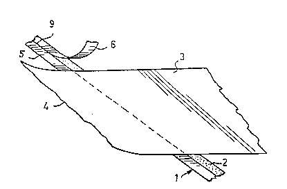
ance wlth Fi~ure 1, one takes a one-slded tape l as
shown in Flgures 8 and 9, whereof a longitudinal zone
~0 of the adhesive surface 2 is exposed, the width of said
zone being substantially half of the width of the tape
and being delimited by that edge of the tape which is
remote from the end edge 4 of the first paper web 3.
When the tape 1 is fastened to the paper web 3 by means
of the adhesive zone 2, the end portion of the paper
web which is located between the end edge 4 and the
edge of the adhesive zone 2 which is closest to this
end edge is torn off from the paper web, whereby the
situation shown in Figure 2 is created. The tearing is
done by hand, and it is made possible by the portion 5
of the protective film which still partly covers the
tape. The removed part of the protective film is indi
cated by reference numeral 6.
When the paper web 3 is fixed to the tape 1,
part 5 of the protective film is removed from the
W09~/08~)3~ PCT~FI90/000l1
?
adhesive surface 2 of the tape, whereby a second lon-
gitudinal zone of ~he adhesive surface is exposed.
Thereafter the second paper web 7 is fixed to the
second adhesive zone of the tape similarly as web 3,
and also ln this case the end portion o~ the web is
torn off as shown ln Figure 4. The accurate tearing,
i.e. trimming, of the end portion is now made possible
by the edge of the first torn web. Thus both ends are
accurately laid face to face without gaps or over
lapping paper. The result is a butt joint between the
paper webs 3,7 as shown in Figure 5, wherein the end
edges of the webs are face to face, fixed to the same
one-s~ded tape 1. Finally, the junction is covered by
an one-sided tape 8 from the s~de opposite tape 1. The
tape 8 is preferably substantially narrower than tape
1. After the tapes have been cut, the junction shown in
Figure 7 is ready.
The tape used in the method o~ the invention has
been shown more closely ln Figures 8 and 9. Th~
adhesive surface 2 o~ the one-sided tape is covered by
parts S,6 of the protective film, which in the shown
embodiment are'equally broad and whose combined width
corresponds to the width of the tape 1. There is a slot
9 between parts 5,6 of the protective film, on account
of which parts 5,6 can be removed from the tape
independently and at separate points of time. Both the
slot 9 and parts 5, 6 of the protective film are conti
nuous in the longitudinal direction of the tape and
extend to the edges of the tape. The bearing layer of
the tape is indicated with the reference numeral 10 in
Figure 9.
The above presents a preferred embodime~t of the
method of the invention and the tape used therein, and
it is obvious that the invention may differ in its
details considerably from what has been presented
WO90/08032 PCT/FI90/OOOtl
~ ^ 7 ~ ' ~
~J ','~ `3
above. Thus the slot 9 may be replaced for instance by
a weakening line or some other arrangement which makes
lt posslble to remove the protective film in steps from
the tape~ Further, it is to be noted that the tape need
not be fixed exactly transverse to the paper webs, but
often it ls advantageous to fix it to the webs somewhat
diagonally, as has been shown ln the figures, whereby
the impact on the printing roll is weakened. The inven-
tlon is particularly suitable for use in connection
with thin and thick paper qualities, whereby the most
suitable thickness for the bearing layer 10 of the tape
is selected in view of the required tensile strength
and the total thickness of the ~unction, but it can
also be used in connection with other equivalent mater-
lals. The width of parts 5,6 of the protective film canbe varied according to need.