Note: Descriptions are shown in the official language in which they were submitted.
. ? ~ ~ ~
TITLE OF THE INVENTION
Projection-type television set
BACKGROUND OF THE INVENTION
FIELD OF THE INVENTION
The present invention relates to a projection-type television set, and
especially relates to an assembly for mounting a screen on which a pictual
image is projected from a projector provided inside the housing of the
television set.
BRIEF DESCRIPTION OF THE DRAWINGS
FIG. 1 is a perspective view allowing a detailed form of a preferred
embodiment of the projection-type television set in accordance with the
present invention;
FIG. 2 is a cross-sectional side view showing the embodiment shown in
FIG. l; -
FIG. 3 is a perspective view showing a broken away portion of the
embodiment shown in FIG. l; -
FIGS. 4(a), 4(b), 4(c) and 4(d) are respectively partial cross-
sectional plan views showing assemby of a screen on a housing in the
embodiment shown in FIG. l;
FIGS. 5(a) and 5(b) are partially sectional plan views showing another
preferred embodiment of a projection-type television set in accordance with
the present invention;
FIG. 6 is the perspective view showing a broken away portion of the
conventional projection-type television set; and
FIG.7 is the perspective view showing a broken away portion of another
conventional projection-type television set.
It will be recognized that some or all of the Figures are schematic
representations for purposes of illustration and do not necessarily depict
the actual relative sizes or locations of the elements shown. ~-
PAT 17682-1 -~
DESCRIPTION OF THE PRIOR ART
In a conventional projection-type television set, a screen 2 is
secured to a housing 1 as shown in FIG.6. First, the screen 2 is fitted
S into a front recessed part la of the housing 1. The periphery of the front
face 2a of the screen 2 is held by a frame 3. The frame 3 is fi~ed to the
housing 1 by screws 4. As a result, the screen 2 is fixed to the housing
1. The screen 2 is removed from the housing 1 by a procedure which is the
reverse to the above-mentioned procedure.
In another conventional projection-type television set, the screen 2
is held between the front edge of the housing 1 and a frame 3 as shown in
FIG. 7, and the frame 3 is fixed on the housing 1 by, for example, the
screws 4.
In the above-mentioned conventional projection-type television set,
lS many screws 4 are necessary for securing the screen 2 to the housing 1 and
thereby a great deal of manual work is necessary for mounting or removing
the screen 2.
Furthermore, with this conventional type of construction, it is
difficult to secure (or remove) the screen 2 to (or from) the housing 1
when the projection-type television sets are stacked up one upon the other,
because of the difficulty of unscrewing the scrsws 4.
.
SUMMARY OF THE INVENTION
The present invention solves the above-mentioned problems and provides
an improved projection-type television set in which the screen can easily
and accurately be mounted on, or removed from a housing, even ~rhen a
plurality of housings are piled up in multiple-stages.
A projection-type television set in accordance with the present
invention comprises:
a housing in which a plurality of projection lenses and CRT displays
are provided;
a plurality of first leaf springs provided at the front respectively ~.
of the top and bottom of the housing, and each leaf spring having a notch;
a plurality of second leaf springs provided at the front respectively - .
PAT 17682-1 ..
- 2 -
~ .
.
3 ?J ~
of the side walls of the housing;
a screen provided in the front opening of the housing;
a pair of horizontal members each having an offset part which is
secured between the top or bottom of the housing and the first leaf
springs, said offset part having a plurality of protrusions which fit in
the notches of the first leaf springs, and having a groove in which a top
edge or a bottom edge of the screen movably fits; and
a pair of vertical frame members provided in gaps between the screen
and the side walls of the housing and held between the second leaf springs
and the side walls.
In the above-mentioned projection-type television set in accordance
with the present invention, the screen is detachably secured to the housing
by couplings of the frame members and the leaf springs, so that the screen
is easily mounted on or removed from the housing even when a plurality of
the projection-type television sets are piled up on one another.
While the novel features of the invention are set forth particularly
in the appended claims, the invention, both as to organization and content,
will be better understood and appreciated, along with other objects and
features thereof, from the following detailed description taken in
conjunction with the drawings.
DESCRIPTION OF PREFERRED EMBODIMENT
A preferred embodiment of a projection-type television set in
accordance with the present invention is described referring to FIGS. 1, 2,
3 and 4(a) to 4td).
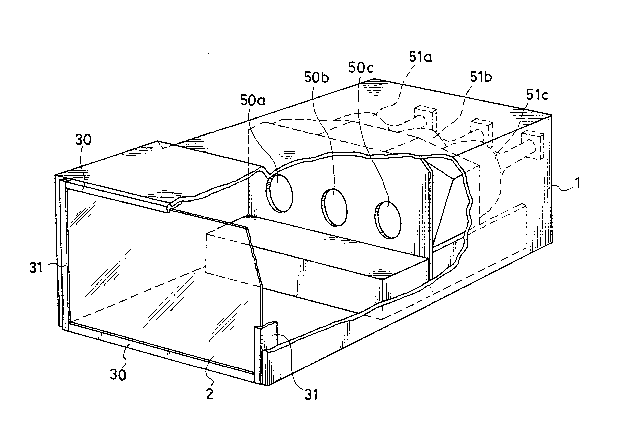
FIG. 1 is a perspective view of the projection-type television set in
accordance with the present invention. FIG. 2 is a cross-sectional side
view of the projection-type television set shown in FIG. 1. FIG. 3 is a
perspective view showing a partially enlarged screen of the projection-type
television set shown in FIGS. 1 and 2. FIGS. 4(a) to 4(d) are respectively
partial cross-sectional plan views showing assembly processes of a screen
on a housing of the projection-type television set in accordance with the
present invention.
In FIGS. 1 and 2, the projection-type television set in accordance
PAT 17682-1
- 3 -
~ 'U -~L .3 ~
with the present invention comprises: a housing l; plural, for example,
three sets of projection lenses 50a, 50b, 50c and CRT displays 51a, 51b,
51c; and a screen 2. The screen 2 is fixed to the front opening of the
housing 1 by horizontal frame members 30 and vertical frame members 31. In
FIG. 2, a plurality of first leaf springs 40 are provided on the top la and
the bottom lb of the housing 1. Also, a plurality of second leaf springs
41 are provided on the side wall~s) lc of the housing 1.
In FIG. 3, an upper edge 2a of the screen 2 fits in a groove 30a in
the horizontal frame members 30, movably, and an offset part 30b of the
horizontal frame members 30 fits in a gap G between the top la of the
housing 1 and the first leaf spring 40. Protrusion 30c of the horizontal
frame members 30 fits in a notch 40a of the first leaf spring 40.
Tolerance bet~een the notch 40a and the protrusion 30c is about 0.2 mm, but
is shown emphasized in the Figures.
Assembly of the screen 2 on the housing 1 is described with reference
to FIGs. 4(a) to 4(b~.
First, the horizontal frame members 30 are moved to one end (right
hand in FIG. 4(a)) with respect to the screen 2 as shown in FIG. 4(a).
Then, the screen 2 is inserted in the front opening of the housing 1
together with the horizontal frame members 30 as shown in the direction of
arrow A in FIG. 4(a).
Secondly, the horizontal frame members 30 are moved on the screen 2 to
the left as shown by arrow B in FIG. 4(b). The movement of the horizontal
frame members 30 is stopped when the protrusions 30c of the frame 30 fit
into the notches 40a of the first leaf springs 40 as sliown in FI~.4(c).
Third, the vertical frame members 31 are put in the gaps between the
screen 2 and the side walls lc of the housing 1 shown by arrow C in FIG.
4(c). The vertical frame members 31 are held to the side walls lc by the
second leaf springs 41. Lateral movement of the screen 2 and the
horizontal frame members 30 is prohibited by the presence of the vertical
frame members 31. As a result, the screen 2 is firmly fixed to the housing
1.
To remove the screen 2 from the housing 1, steps opposite to those
mentioned above are executed.
Another preferred embodiment of a projection-type television set in
PAT 17682-1
- 4 - ~
..
J ~
accordance with the present invention is described with reference to FIGS.
5(a~ and 5(b). FIGS. 5(a) and 5(b) are respectively showing partially
sectioned plan views of another preferred embodiment of the projection-type
television set in accordance with the present invention. Elements having
the same number as those of the first-mentioned embodiment are
substantially the same, and detailed explanations of those elements are
omitted.
In FIGs. 5(a) and 5(b), the second leaf spring 41 is fixed on the side
wall lc of the housing 1 via a spacer 42. The second leaf spring 41 has a
10 protrusion 41a in the center part of the spring arm part thereof. Also,
the vertical frame members 31 have a hole 31a into which the protrusion
41a of the second leaf spring 41 can fit as shown in FIG. 5(b). Thus, the
vertical frame members 31 are more fi~mly held between the side wall lc of
the housing 1 and the second leaf spring 41.
As mentioned above, in the projection-type television set in
accordance with the present invention, the screen 2 is firmly mounted to
the front part of the housing 1 by the engagement of the protrusions 30a of
the hori~ontal frame members 30 and the notches 40a of first leaf springs
40 without using any screws. Also, the vertical gaps between the side
20 walls lc of the housing 1 and the screen 2 are filled by the vertical frame
members 31. Thereby, undesirable vibration of the screen 2 and so on will
not occur. Furthermore, the screen 2 is easily removed from the housing 1
even when a plurality of the projection-type television sets are piled up. ~ ~
Although the present invention has been described in terms of the ~ -
25 presently preferred embodiments, it is to be understood that such
disclosure is not to be interpreted as limiting. Various alterations and
modificatîons will no doubt become apparent to those skilled in the art
after having read the above disclosure. Accordingly, it is intended that
the appended claims be interpreted as covering all alterations and
30 modifications as fall within the true spirit and scope of the invention. ~
: :-
PAT 17682-1
-- 5 -