Language selection

Search

Patent 2045994 Summary

Third-party information liability

Some of the information on this Web page has been provided by external sources. The Government of Canada is not responsible for the accuracy, reliability or currency of the information supplied by external sources. Users wishing to rely upon this information should consult directly with the source of the information. Content provided by external sources is not subject to official languages, privacy and accessibility requirements.

Claims and Abstract availability

Any discrepancies in the text and image of the Claims and Abstract are due to differing posting times. Text of the Claims and Abstract are posted:

  • At the time the application is open to public inspection;
  • At the time of issue of the patent (grant).
(12) Patent: (11) CA 2045994
(54) English Title: STRUCTURE OF COUPLING HEAD PORTION FOR COILED SLIDE FASTENER ELEMENT
(54) French Title: STRUCTURE D'ACCOUPLEMENT DE TETE POUR ELEMENT DE FIXATION COULISSANT
Status: Term Expired - Post Grant Beyond Limit
Bibliographic Data
(51) International Patent Classification (IPC):
  • A44B 19/00 (2006.01)
  • A44B 19/12 (2006.01)
(72) Inventors :
  • MATSUSHIMA, HARUO (Japan)
(73) Owners :
  • YKK CORPORATION
(71) Applicants :
  • YKK CORPORATION (Japan)
(74) Agent: GOWLING WLG (CANADA) LLP
(74) Associate agent:
(45) Issued: 1995-03-28
(22) Filed Date: 1991-06-28
(41) Open to Public Inspection: 1992-01-04
Examination requested: 1991-06-28
Availability of licence: N/A
Dedicated to the Public: N/A
(25) Language of filing: English

Patent Cooperation Treaty (PCT): No

(30) Application Priority Data:
Application No. Country/Territory Date
2-176699 (Japan) 1990-07-03

Abstracts

English Abstract


A coiled slide fastener element made of a
synthetic resin monofilament has a coupling head por-
tion, which has an enlarged width by forming bulging
portions so that firm coupling of a slide fastener can
be realized.


Claims

Note: Claims are shown in the official language in which they were submitted.

CLAIMS
1. A coiled slide fastener element made by bending a monofilament
of synthetic resin so as to have an upper leg portion, a coupling head portion,
a lower leg portion, and a connecting portion in succession, wherein said
coupling head portion comprises:
bent portions on an inner side of said coupling head portion, each of said
bent portions terminating in bulging portions on opposite sides of said couplinghead portion;
said bent portions being substantially semi-circular in cross-section and
confronting each other via flat portion thereof, said flat portions being
substantially in contact with each other;
wherein said bulging portions are relatively thick, and have a gently-
sloped, non-recessed contour; and
whereby said contour and thickness of said bulging portions increases
the coupling area of said coupling head portion.

Description

Note: Descriptions are shown in the official language in which they were submitted.


~OgS994
.
STRUCTURE OF COUPLING HEAD PORTION FOR
COILED SLIDE FASTENER ELEMENT
BACKGROUND OF THE INVENTION
1. Field of the Invention:
This invention relates to a coiled slide
fastener element produced by bending a monofilament of
synthetic resin, and more particularly to the struc-
ture of a coupling head portion for such a coiled
slide fastener element.
2. Description of the Related Art:
There are currently known a variety of coupling
head portions for such slide fasteners which are pro-
duced by stamping a monofilament or pressing the
monofilament by using force to wind the monofilament
around a substantially square mandrel, for example.
In these methods, the coupling head portion is formed
by bending and pressing the monofilament by applying
force.
One example of such a coupling head portion is
shown in FIGS. 7 and 8 of the accompanying drawings.
A coupling head portion 12 is small in thickness, and
bulging portions 13 have steep slopes 14.
With this coupling head portion, the slopes of
the bulging portions are recessed as shown by a solid
line in FIG. 8. Preferably these slopes should be
-- 1 -- ~

204599~
.
gentle or curved as shown by a double-dot line in FIG.
8. Conventionally, these slopes are rather deeply
recessed, thereby making the coupling head portion
small in size and in thickness. When a pair of mating
coupling elements of a slide fastener are coupled,
such coupling head portions have somewhat weak lateral
coupling force, and tend to be disengaged if pulled
strongly in the lateral direction.
SUMMARY OF THE INVENTION
With the foregoing problems in view, it is
therefore an object of this invention to provide a
structure of a coupling head portion for a slide
fastener element which is resistant to lateral pulling
force.
According to this invention, there is provided a
structure of a coupling head portion for a slide
fastener element made by bending a monofilament of
synthetic resin. The structure is characterized in
that bent portions at an inner side of the coupling
head portion and bulging portions are substantially
semi-circular in cross section and confront each other
via flat portions thereof which are nearly or actually
in contact with each other.
With this arrangement, the bulging portions at
the coupling head portion are mount-like with full and
round slopes and large in thickness, thereby enlarging

the coupling area and increasing the coupling force of
the coupling head portion.
BRIEF DESCRIPTION OF T~E DRAWINGS
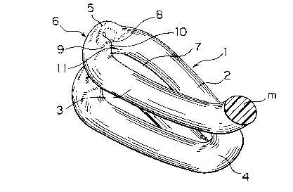
FIG. 1 is a perspective view showing a part of a
coiled slide fastener coupling element according to
one embodiment of this invention:
FIG. 2 is a side elevational view of the slide
fastener element of FIG. l;
FIG. 3 is an enlarged cross-sectional view taken
along line III-III of FIG. 2:
FIG. 4 is an enlarged cross-sectional view taken along
line IV-IV of FIG. 2:
FIG. 5 is a side elevational view showing one
example of a fastener stringer using the slide
fastener element of this invention:
FIGS. 6(A) and 6(B) are cross-sectional views of
monofilaments;
FIG. 7 is a perspective view showing a part of a
conventional slide fastener element: and
FIG. 8 is a front elevational view of the slide
fastener element of FIG. 7.
DETAILED DESCRIPTION
One embodiment of this invention will now be
described with reference to FIGS. 1 to 4. As shown in
FIG. 1, a coiled slide fastener element 1, which is
made by bending a monofilament of synthetic resin,

~:04599~
.
comprises an upper leg portion 2, a coupling head por-
tion 6, a lower leg portion 3, and a connecting por-
tion 4, all of which are formed in succession by turn-
ing and bending the monofilament. The coupling head
portion 6 includes bulging portions 5 and bent por-
tions 8, 9. An inner side of the coupling head por-
tion 6 and the upper and lower leg portions forms a
hollow space 7 for receiving a mating coupling head
portion. The monofilament m composing the coiled
slide faster element 1 is either circular or oval in
the cross section as shown in FIG. 6(A) or 6(B).
The circular or oval monofilament m is turned
and bent to form the coupling head portion 6. At the
coupling head portion 6, the monofilament becomes sub-
stantially semi-circular in the cross section, taken
along line III-III in FIG. 2, as shown in FIG. 3, and
serve as bent portions 8, 9. The bent portions 8, 9
confront each other via their flat portions 10, 11
which are nearly or actually in contact with each
other. The monofilament is pressed at the inner side
of the coupling head portion to form bulging portions
5 on opposite sides of the coupling head portion 6.
The bulging portions 5 are mount-like with gentle
slopes and large in thickness, thereby increasing the
coupling area of the coupling head portion to realize
firm coupling.
-- 4

zoa~5994
.
The coiled slide fastener element 1 of the fore-
going structure may be woven into a fastener tape tl
during weaving as shown in FIG. 2, or may be attached
to a slide fastener tape tZ by sewing or by weaving as
shown in FIG. 5.
According to this invention, the coupling head
portion has an enlarged width due to the bulging por-
tions which are gently sloped, so that firm coupling
of a slide fastener can be realized. Therefore, the
slide fastener can remain coupled even when a strong
lateral pulling force is applied thereto.

Representative Drawing
A single figure which represents the drawing illustrating the invention.
Administrative Status

2024-08-01:As part of the Next Generation Patents (NGP) transition, the Canadian Patents Database (CPD) now contains a more detailed Event History, which replicates the Event Log of our new back-office solution.

Please note that "Inactive:" events refers to events no longer in use in our new back-office solution.

For a clearer understanding of the status of the application/patent presented on this page, the site Disclaimer , as well as the definitions for Patent , Event History , Maintenance Fee  and Payment History  should be consulted.

Event History

Description Date
Inactive: Expired (new Act pat) 2011-06-28
Inactive: IPC from MCD 2006-03-11
Inactive: Office letter 2000-01-18
Letter Sent 1999-06-28
Grant by Issuance 1995-03-28
Application Published (Open to Public Inspection) 1992-01-04
All Requirements for Examination Determined Compliant 1991-06-28
Request for Examination Requirements Determined Compliant 1991-06-28

Abandonment History

There is no abandonment history.

Fee History

Fee Type Anniversary Year Due Date Paid Date
MF (patent, 7th anniv.) - standard 1998-06-29 1998-03-19
MF (patent, 8th anniv.) - standard 1999-06-28 1999-03-11
MF (patent, 9th anniv.) - standard 2000-06-28 2000-04-04
MF (patent, 10th anniv.) - standard 2001-06-28 2001-04-11
MF (patent, 11th anniv.) - standard 2002-06-28 2002-05-16
MF (patent, 12th anniv.) - standard 2003-06-30 2003-05-20
MF (patent, 13th anniv.) - standard 2004-06-28 2004-05-17
MF (patent, 14th anniv.) - standard 2005-06-28 2005-05-09
MF (patent, 15th anniv.) - standard 2006-06-28 2006-05-05
MF (patent, 16th anniv.) - standard 2007-06-28 2007-05-07
MF (patent, 17th anniv.) - standard 2008-06-30 2008-05-12
MF (patent, 18th anniv.) - standard 2009-06-29 2009-05-14
MF (patent, 19th anniv.) - standard 2010-06-28 2010-05-11
Owners on Record

Note: Records showing the ownership history in alphabetical order.

Current Owners on Record
YKK CORPORATION
Past Owners on Record
HARUO MATSUSHIMA
Past Owners that do not appear in the "Owners on Record" listing will appear in other documentation within the application.
Documents

To view selected files, please enter reCAPTCHA code :


To view images, click a link in the Document Description column. To download the documents, select one or more checkboxes in the first column and then click the "Download Selected in PDF format (Zip Archive)" or the "Download Selected as Single PDF" button.

List of published and non-published patent-specific documents on the CPD .

If you have any difficulty accessing content, you can call the Client Service Centre at 1-866-997-1936 or send them an e-mail at CIPO Client Service Centre.


Document
Description 
Date
(yyyy-mm-dd) 
Number of pages   Size of Image (KB) 
Cover Page 1995-03-28 1 17
Abstract 1995-03-28 1 9
Description 1995-03-28 5 144
Claims 1995-03-28 1 22
Drawings 1995-03-28 3 56
Representative drawing 1999-04-16 1 15
Fees 1997-05-16 1 63
Fees 1996-05-14 1 65
Fees 1994-04-27 1 72
Fees 1995-05-01 1 80
Fees 1993-03-26 1 49
Examiner Requisition 1994-04-15 2 85
Prosecution correspondence 1991-11-12 1 37
Prosecution correspondence 1994-10-12 3 117
Prosecution correspondence 1994-12-20 1 30
Prosecution correspondence 1994-12-28 3 91
Prosecution correspondence 1994-11-29 1 47
Courtesy - Office Letter 1992-02-26 1 38