Note: Descriptions are shown in the official language in which they were submitted.
T y ra~i~~cA~~n~!gbf~
N\J ~1J~4~~. J
1 ~~4b~~~
METHOD OF OPERATING I.C. ENGINES
AND APPARATUS THEREOF
BACKGROUND OF THE INVENTION
Field of the Invention
This invention relates to an improved method of
operating unthrottled internal combustion engines at
compression ratios lower than required for diesel
engines. Moreover, this invention relates to means For
ZO operating glow plugs in uwthrottled engines at lower
plug temperatures than would be required with
non--catalytic glow plugs of the same size and geometry.
In one specific embodiment, the plug temperature is
provided with temperature determining means and
electrical power is controlled to maintain the plug
walls at a value determined by the engine speed and
power output.
This invention also relates to catalytic glow
plugs capable of igniting goals at lower temperatures
20' than a non-catalytic glow plug of the same size and
shape.
Brief Descr'i~.tion of the Prior Art
Existing diesel engines achieve a significantly
higher thermal efficiency than conventional gasoline
engines in automotive use and emit acceptable levels of
carbon monoxide and light hydrocarbons. However, soot
and nitrogen oxide levels are high and compression
ratios are much higher than the optimum for maximum
fuel economy. Moreover diesels are relatively hard to
start as compared to automotive gasoline engines, even
with electrically heated glow plugs, and require high
" '':::''~:'"~' ~. .-'>i-'l=.j.~~
.~'i: : .. ~_. - .._. -.
2
cetane fuels. This is especially true of the lower
compression diesels such as the large lower speed
engines. With use of glow plugs, short plug life can
be a problem particularly under operating conditions
which require higher plug operating temperatures, such
as cold starting at arctic temperatures.
As a means of improving cold starting performance
of conventional high compression diesel engines with
glow plugs, the use of catalytically self-heating glow
plugs has been proposed tU.S. patent 4,345,555). Such
self-heating plugs are said to maintain a preset plug
temperature by exothermic catalytic reactions after
termination of the initial electrical heating of the
plug during starting. A self-heating plug is said to
maintain a higher temperature than a non-catalytic
diesel glow plug and is further said to maintain a
temperature above that required for ignition of fuel by
. a non-catalytic plug. It is taught that the catalyst
should comprise a porous carrier, presumably to achieve
greater surface heating (it is well known that such
porous supports provide a greater surface area for
catalytic reactions than a non-porous support).
Self-heating plugs can be expected to offer no
improvement-in plug life as compared to conventional
glow plugs inasmuch as such self-heating plugs are said
to maintain a higher temperature than conventional
plugs. Plugs which are effective at lower plug
temperatures ~rou7.d allow easier starting under
adverseconditions and would enable starting lower
ambient temperatures.
In addition to the above cited shortcomings,
conventional diesels cannot be operated at low enough
'lYl~ Jl~/'1!'J~:.1 ' -f i a~ i i ~.)'mn wv.>rw
fd ~.~ 3 :) U ro :i
3
compression ratios for maximum efficiency and
conventional diesels cannot efficiently utilize low
cetane fuels such as methanol and gasoline. Although
in-cylinder catalysts previously proposed can improve
efficiency and reduce emissions of soot and nitrogen
oxides, retrofitting of existing engines is not always
economically feasible, especially with small automotive
diesels.
Conventional spark ignition engines are typically
ZO less efficient than diesel engines in spite of
operating in close appaximation to the constant volume
combustion Otto cycle, a more efficient cycle than the
diesel cycle. This lower efficiency is believed to
result primarily from the throttling losses associated
with the requirement for spark ignition. Spark
ignition requires near stoichiometric fuel-air mixtures
for flame propagation. To control power levels, the
amounts of fuel and air must both be varied in step.
This requires throttling of the inlet air with
resultant loss of pressure energy. Octane limits of
fuels typically limit compression ratios to below
optimum levels. Operation of spark engines without
throttling of the inlet air could result in an engine
more efficient than the diesel, even if such engines
were limited to below optimum compression ratios.
Attempts have been made to operate unthrottled
engines at lower than diesel compression ratios. ~Iith
compression ratios too low for autoignition, an
ignition source such as a spark plug or a continuously
operating glow plug is needed. Thus, stratified charge
spark-ignited engines of various designs, both piston
and rotary, have been proposed. To date, such engines
avc~ ~m~~2~ -' ' ~~-rius~i~ua~~
~~ 4 R ~ ~: ~.! l '-t
~~ 17 =t ~J ~I ~ v
4
have not won acceptance. for use with heavy fuels such
as diesel and jet A, spark plug fouling has been a
severe problem leading to the use of glow plugs.
Although use of glow plugs eliminates the fouling
problem, a higher glow plug temperature is required for
operating a low compression ratio engine than for cold
starting a diesel engine. This is believed to be
because the compression temperature of a low
compression engine is lower than that of a high
ZO compression diesel at typical cold start conditions.
Another factor is that the ignition temperature of
hydrocarbon fuels may be higher at lower pressures than
at higher pressures. With the high continuous
operating temperature required using conventional glow
plugs in a low compression engine, typically in excess
of about 1375 degrees IC, plug heat losses must be
minimal if plug power requirments are to be acceptable
. at all operating conditions. With such a low heat loss
plug it has been found that not only is no electrical
power required at full load operation but that plug
temperatures can even exceed the temperature limits of
a high temperature material such as silicon nitride.
Although much larger plugs could be used to Tower
operating temperature to so~ae extent, power
requirements would be excessive and space might not be
available. The capability to ignite fuels at lower
compression temperatures has implications for cold
starting of conventional diesels. even with
conventional high compression diesels, at low enough
ambient temperatures the compression temperature will
be as low as in a 10/1 compression ratio engine at the
usually prevailing ambient temperatures.
'-$ ~? :7 ~~ P3
."
The method of the present invention overcomes the
limitations of the prior art by providing glow plugs
capable of ignition at a surface temperature as much as
5 300 degrees Kelvin lower than required for a
non-catalytic glow plug of the same size and
configuration and by providing an economical means of
operating internal combustion engines at lower
compression ratios without throttling of the inlet aix
l0 and the throttling losses associated therewith. Use of
the low ignition temperature catalytic glow plugs of
the present invention in an internal combustion engine
enables c~lic?cer starts inasmuch as less time is
required to heat a plug to a lower temperature.
Equally important, by providing a means of mare rapid
ignition at a lower plug temperature, combustion
efficiency in engines is improved and emissions
. reduced. It is believed that the lower ignition
temperature and more efficient combustian is a
2o consequence of free radical production by the low
porosity catalytic ignition surfaces of the present
invention. It is known in the art that free radicals
are combustion reaction intermediates.
SUIHMA.~2Y OF THE INVENTI01~1
According to the present invention, an internal
combustion engine is fitted with a catalytic glow plug
and control means to maintain the catalytic surface of
the glow plug at a specified temperature below that
required for rapid ignition of fuels with an equivalent
geometry nonrcatalytic conventional glow plug in the
same engine. Typically the specified temperature is 50
to 300 degrees Kelvin lower than for an equivalent
Svu~r~r.35s.t :y. : ~~; ~~~~~~i:.-u;:~u
_ , ,:.
~s~~~~~~;.~
s
non-catalytic plug, more preferrably ?5 to 150 degrees
Kelvin lower but may be as much as 600 degrees Kelvin
lower with fuels which are especially reactive
catalytically. The catalytic surfaces of the glow plug
may comprise a base metal oxide ignition catalyst or a
platinum metal catalyst. for best ignition
performance, the catalyst surface is of low porosity,
preferably substantially nonporous. An essentially
nonporous nature of the catalyst surface is
advantageous to avoid permeation of fuel into 'the
catalyst which would tend to cool the catalyst on
contact with injected fuel droplets. Advantageously,
the catalytic surface may be sintered at a temperature
higher than the intended maximum operating temperature
prior to use.
In operation of the engine, the glow plug is
advantageously electrically heated to bring it to the
required operating temperature, typically within the
range of about 700 degrees Kelvin to about 100 degrees
Kelvin depending on factors such as engine compression
ratio, engine speed, inlet air temperature and the fuel
composition. Those skilled in the art will appreciate
that a specific optimal temperature for operating a
specific engine will be dependent upon. the above
factors, but can be readily determined by trial in the
engine. After heating of the plug8 the engine is
started. Fuel is injected such that at least a portion
of the fuel aontacts the catalytic surface prior to the
time of maximum compression. Electrical power is
controlled such that the glow plug is maintained at a
temperature appropriate for rapid ignition of the fuel
at the given engine operating conditions. With lower
rv ti ~lir'iii~J.~: i ~ .~ . ..: / L.':~~SJI::L'~::.i7
i
r-W ~ ~a v :,:
7
compression ratio engines, continued electrical heating
is usually needed at the lower power levels. Typically
however, no electrical power is reguired at full engine
power operation because heat transfer from the hot
combustion gases of fuel combusting at temperatures in
excess of 2000 degrees Kelvin is sufficient to heat
even a non-catalytic plug to a temperature sufficient
for ignition of fuel. Because catalytic oxidation of
the fuel on the catalytic glow plug surface results in
1o high concentrations of ignition enhancing free radicals
in the adjacent gas, a catalytic glow plug of the
present invention requires a lower surface temperature
for ignition of fuel and thus less electrical heating
than a non-catalytic glow plug for rapid ignition of
fuel. Operation of an internal combustion engine in
accordance with the present invention offers greater
ease in starting and reduced eynissions of soot, not
. only with conventional diesel fuels but also with low
cetane fuels such as methanol, ethanol, and other
alcohols and oxygenated fuels. Cold starting is made
possible even at temperatures below 240K and even as
low.as 210 or 200K provided the fuel is pumpable and
the starting motor can crank the engine. With a glow
plug according to the present invention, oxygenated
fuels such as methanol ignite even mare readily than
diesel fuels. This is of considerable importance since
it greatly increases the availability of fuels suitable
for use in diesel engines and in the more efficient
lower compression ratio unthrottled internal
compression ratio engines made practical by use of glow
plugs of the present invention.
>V~ ~/i195' l ~' ' P~C'~ / i~~~ti/r3ti~~~
:., : : ,. ~ -
~~ j i c~. .;~ j ~, ~
8
zn the present invention, improved ignition of the
fuel by virtue of catalytic action is believed to
result from surface oxidation of a minor amount of the
fuel. Tt is believed that the catalyst injects radical
species into the gas phase, thus lowering the
temperature required for gas phase combustion. Tt is
well known that radical species can speed up
combustion. Accordingly, for effective ignition
according to this invention, the required catalyst
temperature is significantly lower than required with a
non-catalytic plug thus reducing the amount of electric
power required to achieve rapid ignition at low engine
power levels in a low compression ratio engine. At
full engine power output no electrical power should
normally be recguired. Even at compression ratios lower
than required for autoignitian, at full engine power
combustion temperatures have been found to be high
enough to maintain even non-catalytic glow plug
surfaces at a temperature high enough for ignition of
fuel with no electrical power required.
. At surface temperatures below those required for
catalytic ignition of the fuel, the presence of a
catalyst can even delay gas phase combustion, thus the
importance of controlling plug temperature. This
~5 result is believed to stem from quenching of radicals
generated in the gas phase. It has long been known
that such quenching of free radicals is promoted by
active catalyst surfaces. It is believed that porous
catalytic surfaces are such poor ignition catalysts
because the catalyst pores can not only trap fuel but
because the pores can trap free radicals long enough
Wt~ ~NH~2i ~ x ~'i i u:3iviiririiov
;,., ~:~
for radical recombination, thus the need to minimize
catalyst porosity. Conventional high surface area
catalysts are particularly ineffective for ignition,
even though such catalysts are much more active than
nanporous igniters for surface oxidation and surface
heating.
Although quenching of radicals has been suggested
as a means to inhibit gum formation prior to spark or
autoignition, the resulting inhibition of combustion is
l0 disadvantageous inasmuch as such inhibition can quench
combustion prior to completion resulting in high
emissions of hydrocarbons and carbon monoxide. In the
present invention the electrical power required may be
reduced in low load operation by a pilot injection of
fuel immediately preceed:ing injection of the main fuel
charge or alternately by earlier timing of the
injection of the fuel charge.
BRIEF DESCRIPTION OF THE DRAWINGS
This invention can be further understood with
reference to the drawings in which
FIG. 1 is a schematic of a system of the present
invention.
FIG. 2 is a schematic of a predictive control
system.
~5 FIG. 3 is a sectional view of a conventional
diesel glow plug which has been modified by coating
with an ignition catalyst.
DETI~.IL,ED DESCRIPTION OF PREFERRED
EMBODIMENTS OF THE INVENTION
This invention relates to a method of aperating a
low compression unthrottled engine wherein fuel and
compressed air are contacted with the catalytic
v. ( ) C
''VC) ~(ti0~~3i 'rL ~ i ~i5~uiuv~u
ignition surface of a catalytic glow plug maintained by
electrical heating at a temperature sufficient for
ignition of the fuel, whereby starting of the engine is
facilitated and combustion efficiency during operation
5 is improved even with engine compression ratios below
14 to 2 or even with compression ratios below about ten
or twelve to one. Tn one embodiment a catalytic
coating is firmly affixed to the surface of a
conventional diesel glow plug. In another embodiment
10 the walls of the glow plug tip, ie: ignition element,
are formed of a catalytic material, preferrably a
catalytic base metal oxide ceramic. In still another
embodiment the glow plug is provided with temperature
determining means and the electrical power is
controlled to maintain the walls of the glow plug above
a predetermined temperature. The catalyst typically
comprises a base metal oxide or noble metal ignition
catalyst. Injection of the fuel is timed such that at
least a portion of the fuel contacts the catalyst
surface prior to the point of maximum compression.
More specifically, this invention relates to
catalytic glow plugs and the means to maintain a glow
plug catalytic ignition element at an operational
temperature in an unthrottled low compression engine
during engine start-up and during operation at less
than full load.
The present invention is further described in
connection with the drawings. As shown in figure 1, in
one preferred embodiment the catalytic system consists
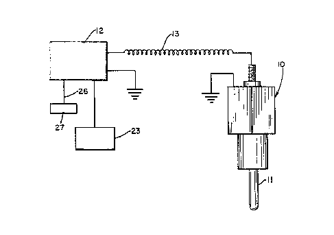
of a glow plug 10 having an ignition element (tip) 17.
with a nonporous surface comprising an ignition
catalyst and temperature control unit 12 which feeds
svllnW mme~~v . . bhTiviC~l(1 ~nne1<n
,_ _ _. ... ~~. 1 ~ f I ~J_.~r.~.yw>.,
11
power to plug 10 via line 13. Control unit 12
determines the temperature of the catalytic surface of
plug tip 11 by measuring the current and voltage
applied to plug 10 and calculating the load resistance
which is a function of the temperature of plug tip 11.
Control unit 12 is designed to supply electrical power
to plug 10 only as needed to maintain a predetermined
temperature of tip 11, which advantageously may be a
function of engine operating parameters including load,
speed, and inlet air temperature. Advantageously, a
preferred method is predictive control of the glow plug
temperature using a computer. Control unit 12 may be a
conventional unit known in the art, as for example such
as the Condarcure units available commercially. As
shown in figure 2, process control computer 22,
hereinafter referred to as the predictive controller,
is preprogrammed to supply power to glow plug 10 during
_ starting and thereafter tci supply power as a function
of the power level setting of engine fuel injector pump .
23, typically maintaining plug tip 11 at a temperature
at least about 75K lower than required at lower power
settings of fuel injector pump 23 than would be
required for a non~catalytic glow plug. Controller 22
may be connected via line 26 to optional inlet air
temperature sensor 27 and programmed to apply increased
electrical power at lower inlet air temperatures.
During engine operation controller 22 monitors plug
catalyst temperature by measurement of the current and
voltage applied to plug 10 as described above. the
computer 22 is a conventional hardware item
commercially available.
CA 02046923 1999-09-07
12
Figure 3 shows an expanded sectional-in-part view of a conventional
glow plug 30 to which a coating of a refractory metal oxide 32 has been
applied
by sputtering to plug tip 31. The metal oxide preferably has a melting point
of
at least about 2000K. To maximize thermal shock tolerance and to minimize
thermal lag it is preferred that coating 32 be thin, less than 10 mils thick
and
preferably less than 2 mils or even less than 0.5 mils. Only a minimal
thickness is required, as for example 0.0001 mils. Ignition catalyst 33
comprises an overcoating of a portion of the surface of coating 32; preferably
a major proportion (at least 51 percent). Suitable ignition catalysts include
the
low vapor pressure platinums group metals, such as Pt, Pd, Rh and the like;
refractory base metal oxide ignition catalysts, such as CoO, NiO, and the like
and high temperature stable base metal oxide compounds such as the
perovskites. Alternatively, the oxide coating 32 may itself comprise the
catalytic surface 33 if a catalytic material is used for coating 32. Methods
of
applying suitable catalytic coatings are known in the art. Especially
advantageous for the purposes of this invention is the ignition catalyst
coating
and method described in U.S. patent 4,603,547. The catalytic coating of this
patent, which preferably comprises a noble metal catalyst such as platinum,
chemically bonded to a thermal barrier coating, will have the function of
reigniting the fuel-air mixture in the event of a flame-out. Reignition will
result
as a consequence of the combined effects of fuel, catalyst, air and
sufficiently
high temperatures. A suitable method of applying the catalytic relight coating
to the gas turbine combustion chamber is shown by the following example: The
inner surface of the combustion chamber is previously coated with a zirconium
oxide, yttrium oxide thermal barrier. The surface to be coated with the
catalytic
coating is cleaned if necessary by vapor degreasing to assure freedom from
dirt,
oil or grease. If necessary, suitable masks are employed on surface areas
where
no catalytic coating is desired. A base coat is first applied comprising
chloroplatinic acid, zirconyl nitrate and aluminum nitrate, with instruments
of
such design that no metallic parts come in contact with the coating. This
CA 02046923 1999-09-07
12A
material is applied in light even coats to prevent running. After each coat is
applied it is dried in a forced circulating air oven at approximately 200 DEG
F.
for fifteen minutes at heat and then at approximately 300 DEG F. for twenty
minutes at heat. After a premeasured quantity of base coat has been applied in
the aforesaid manner, a top coat is applied in one coat to the specified
areas.
The part is then dried in the aforesaid manner and any mask material carefully
removed. The coated part is then cured in an air circulating fiirnace by
heating
to approximately 250 DEG F. and holding for twenty minutes, raising the
temperature to approximately 1300 DEG F. , and holding at that temperature for
one hour. The part is then furnace cooled to below 1000 DEG F. and then air
cooled to room temperature. During this calcination process the noble metal
compounds convert to pure metals and the zirconium and aluminum oxides
convert to ceramic oxides. The noble metal is bonded to the thermal barrier
coating by a matrix of ceramic material similar in composition to the thermal
barrier itself. Care is taken to avoid accumulation of fumes in the furnace.
The
part is then enclosed in a sealed container. Preferred proportions of the base
and
top coats are as follows: Base Coat a. 1.1 gm platinum metal in the form of
chloroplatinic acid b. 0.5 gm aluminum nitrate c. 3.0 cc zirconyl nitrate; Top
Coat a. 0.5 gm palladium chloride b. 1.0 cc water c. 3.0 cc zirconyl nitrate
For enhancement of diesel engine ignition, it is important that the catalytic
glow plug be maintained at a temperature at which the catalyst used is
effective
for ignition of the fuel. In general the plug tip is maintained at a
temperature
of about 75 to 300 degrees Kelvin lower than required to start a diesel
a~r~ ontnn:?s . ., ~~it ynniruyn
~a: .a:w;~ ~-;
3 i .
13
engine using a conventional glow plug. The required
plug temperature is readily determined for any fuel by
contacting a flammable fuel air mixture with a heated
glow plug. The control means is then readily designed
to maintain the catalytic glow plug at a temperature at
which the catalyst is effective for rapid ignition.
Preferrably, during cold starting of an engine the glow
plug is maintained at a temperature at least about 50
degrees Kelvin higher than the desired control
temperature during nox°anal operation of the engine.
This allows faster start--ups. During normal operation
after engine start-up, electrical power need be
supplied to the catalytic glow plugs only if the plug
temperature falls below the predetermined control
temperature. It should be understood that during full ,
load operation of the engine, combustion of fuel in the
engine will typically maintain the catalytic plug at a
. temperature above the control temperature without the
necessity of electrical heating. With conventional
diesels not requiring glow plugs once started, use of
the catalytic plugs of this invention as a starting
aid,. allows cold starting of a cranking engine at
ambient temperatures as low as 200K. Even with engine
compression ratios below about 12 to 1, it may be
possible to operate at idle without electrical heating
after initial start-up, especially with an oxygenated
fuel as for example methanol.
With conventional glow plugs, the high
temperatures required for effective surface ignition of
fuels not only impose a high power requirement but
shorten glow plug life if the plugs are kept in
continuous operation. tJse of catalytic glow plugs in
. or~i~ ipwte jnnQ~cy
_:
Z4
accordance with the present invention reduces power
requirements in continuous operation by reducing the
surface temperature required for ignition of fuels.
Glow plugs with oxide ceramic ignition elements are
advantageous because such plugs can better tolerate the
very high temperature oxidizing conditions typical of
full load operation. Tt is feasible to better insulate
such a plug against heat loss, further minimizing the
electrical power required at low load. With plugs of
conventional materials it has been found necessary to
allow sufficient heat loss to limit full load maximum
temperature to an acceptable level, ie: about 1500
degrees Kelvin or less. Moreover, such conventional
plugs having a relatively narrow operating temperature
range impose severe design requirement's on the
temperature controller to avoid overheating of the plug
should electrical heating requirement change abruptly
. as during a ragid engine acceleration. Glow plugs
capable of igniting fuels at lower temperatures greatly
simplify controller design and make it possible to
assure that the plug temperature will not exceed
allowable limits. Cooling fins on the plug body may be
employed to limit maximum plug temperature by heat
transfer to the ambient air.
The following examples describe the means of
making and using the innvention and set forth the best
mode contemplated for carrying out the invention but
are not to be coaistrued as limiting.
EXA.MPhE 1: To demonstrate the superiority of low
ignition temperature catalytic glow plugs under adverse
operating conditions, an NGK diesel glow plug was
obtained and a thin non-porous coating of alumina
.a.. .. yr~~mn~n innnin
YYV Jtii~v~~i.i ~ - .-.l JJ~'.J:
c'a .7 .'i
iro ~~ _ . ~n ._ ..
applied by sputtering to the ignition surfaces. An
aqueous solution containing chloroplatinic acid was
then applied to the alumina surface and the plug heated
electrically to activate the platinum. The coated plug
5 was then compared to an uncoated NGK plug in a d'ohn
Deere rotary engine in Deere~s 20-1 test cell.
Operating at 4800 RPM and 17 percent of full load pawer
output, with the catalyst coated plug in the test rotor
chamber the engine operated satisfactorily at plug
10 temperatures as low as 1045 degrees Kelvin. With the
conventional.uncoated NGK glow plug in the test rotor
chamber, the engine could not be operated as low as 17
percent power output even with the plug temperature at
1336 degrees Kelvin. 3nTith the engine operating at a
15 higher power level with the uncoated plug at 1336
degrees Kelvin, reduction in the power setting resulted
in combustion failure and engine shutdown.
. EXAMPLE 2: To test the durability of catalyst
coated conventional glow plugs,.four Volkswagen ~VW)
20 diesel glow plugs were coated~with a thin coating of
zirconia (less than about 2 mils thick) and,a major
portion of the surface was then additionally solution
coated with a platinum/alumina/zirconia catalyst
composition.- One of the glow plugs of a diesel Rabbit
25 engine was then replaced with one of the catalytic
plugs. After a several thousand miles the catlytic
plug was removed for examination. The plug removed
showed no visible signs of damage.
EXAMPLE 3: In accordance ;with the present
invention, a four cylinder diesel engine of a VW Rabbit
is modified by replacing the conventional glow plugs in
r ~ O!'T/1I4C~11 /(U1Q~'(1
'll~~ ~iI,V~'Ji~ r 1.....n.n..
4 _~ _
a1 :~
~r aJ ~ 4J' i~ ~r ci
16
the combustion chamber of each cylinder with catalytic
glow plugs as used in the durability test just
described in Example 2, and by changing the head gasket
to lower the compression ratio below about 14/1. In
operation of the engine the ignition catalyst surface
of the plug is electrically heated to a temperature
high enough to be effective for vaporization of diesel
fuel and ignition of vaporized fuel. The electrical
heating is applied as needed using a predictive
controller to maintain the catalyst at a predetermined
operating temperature at least about 150 degrees Kelvin
lower than required for ignition of diesel fuel using a
non-catalytic glow plug in the engine. Air is
compressed in the combustion chamber and diesel fuel is
injected in the normal manner at a time approximately
three crank angle degrees later than recommended by VW.
The fuel is ignited by contact with the heated catalyst
. with the resulting combustion resulting in a combustion
wave in the vicinity of top dead center with minimal
formation of soot.