Language selection

Search

Patent 2046976 Summary

Third-party information liability

Some of the information on this Web page has been provided by external sources. The Government of Canada is not responsible for the accuracy, reliability or currency of the information supplied by external sources. Users wishing to rely upon this information should consult directly with the source of the information. Content provided by external sources is not subject to official languages, privacy and accessibility requirements.

Claims and Abstract availability

Any discrepancies in the text and image of the Claims and Abstract are due to differing posting times. Text of the Claims and Abstract are posted:

  • At the time the application is open to public inspection;
  • At the time of issue of the patent (grant).
(12) Patent: (11) CA 2046976
(54) English Title: LOCKING MEANS AND PANEL ASSEMBLY INCORPORATING SUCH LOCKING MEANS
(54) French Title: DISPOSITIFS DE FIXATION ET ENSEMBLE DE PANNEAUX MUNIS DE CES DISPOSITIFS
Status: Expired and beyond the Period of Reversal
Bibliographic Data
(51) International Patent Classification (IPC):
  • F16B 12/02 (2006.01)
  • A47G 5/00 (2006.01)
  • E01F 13/02 (2006.01)
  • E04B 2/74 (2006.01)
  • G09F 7/18 (2006.01)
(72) Inventors :
  • HANNA, RONALD DAVID (Canada)
(73) Owners :
  • G.D. HANNA INCORPORATED
  • DISPLAY PRODUCTS INC.
(71) Applicants :
  • G.D. HANNA INCORPORATED (Canada)
  • DISPLAY PRODUCTS INC. (United States of America)
(74) Agent:
(74) Associate agent:
(45) Issued: 2002-05-07
(22) Filed Date: 1991-07-12
(41) Open to Public Inspection: 1993-01-13
Examination requested: 1998-07-13
Availability of licence: N/A
Dedicated to the Public: N/A
(25) Language of filing: English

Patent Cooperation Treaty (PCT): No

(30) Application Priority Data: None

Abstracts

English Abstract


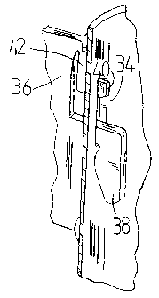
A new attachment plate is provided for securing components of
panel assemblies to a mounting post, the attachment plate
incorporating a securing hook together with a stop means. The
attachment plate includes a projecting hook which mates with a
slot in a mounting post structural member. The hook is of a
lesser length than the slot in the post, and a further
projection as a stop means is provided on the attachment plate
which also enters the slot and restrains reversed relative
movement between the plate hook and the post slot, so as to
limit or prevent undesired disassembly of a panel from the post.
The application of an upward impact to the plate causes a cam
surface on the stop means to contact the upper end of the
mounting post slot. This deflects the stop means out from the
slot, to enable removal of the hook from the slot, for panel
disassembly from the post. Also provided is a hooked supporting
plate incorporating pairs of flexible presser tabs, to
compensate for manufacturing tolerances. The laterally extending
tabs engage outer surfaces of the mounting post and provide
stabilization of a multi-panel assembly against sway.


Claims

Note: Claims are shown in the official language in which they were submitted.


THE EMBODIMENTS OF THE INVENTION IN WHICH AN EXCLUSIVE PROPERTY
OR PRIVILEGE IS CLAIMED ARE DEFINED AS FOLLOWS:
1. An attachment system having a slotted support post; at
least one slot of predetermined length and width
penetrating a wall portion of the post and extending
parallel with the main axis of the post; a support plate
for attachment of an upright panel to the post, said plate
having a hook portion for insertion within the post,
through the slot, to engage an interior surface of the post
adjacent the slot; and at least one flexible restraint
means secured to the support plate, to engage the post in
restraining relation thereagainst each said restraint means
including two contact pads extending laterally, on opposite
sides of said support plate, in resilient, attached
relation thereto, in use to form with said hook a
triangulated, lateral sway restraint relative to said post
and said panel, to reduce lateral swaying of said panel
relative to the post.
2. The attachment system as set forth in claim 1, said
restraint means including a stop means extending in the
plane of said plate for entry within said slot, to limit
movement of said hook in a withdrawal sense from said slot
said stop means having an inclined upper edge cam surface
portion, inwardly and downwardly inclined relative to said
slot for entry partially within the slot below and adjacent
the upper edge of the slot, to preclude normal withdrawal
of the hook portion upwardly along the slot; the stop means
being mounted on a resilient, cantilevered edge portion of
the plate whereby an upward application of a moderate
impact to said plate said cam edge is forced outwardly of
said slot, to clear said stop means from the slot and
permit withdrawal of the hook portion from the slot.
3. The attachment system as set forth in claim 1, said
restraint means including at least one resilient,
cantilevered edge portion of said plate having a said
contact pad mounted thereon, to enable deflection of said
contact pad towards said plate, substantially in the plane
of the plate.
4. The attachment system as set forth in claim 1, said support
plate having a thickness substantially less than the width
of said slot, to permit lateral canting of said support
plate within said slot.

5. The attachment system as set forth in claim 1, said support
plate being of engineering plastic of sufficient thickness
to facilitate safe lateral bending thereof in a load
supporting mode.
6. The attachment system as set forth in claim 1 in
combination with a plurality of panels and posts in secure
attached relation therewith by way of a plurality of said
support plates.
7. The attachment system as set forth in claim 1, said support
plate including one said restraint means located in spaced
relation from the top of said support plate, to enable
removal of a top portion of the plate while retaining said
one restraint means adjacent thereto.

Description

Note: Descriptions are shown in the official language in which they were submitted.


~~4f 9'~6
LOCKING MEANS AND PANEL ASSEMBLY INCORPORATING
SUCH LOCKING MEANS
TECHNICAL FIELD
This invention is directed to a panel attachment system, and
in particular to a locking attachment system, one embodiment
thereof incorporating a detachment capability.
BACKGROUND ART
In the assembly of displays and partitions much use is made of
hooking attachment brackets, secured to a display panel or a
partition panel, in combination with special hollow posts to
which the panels are secured.
Owing .to the need for rigid, reliable assembly, it has been
the practice to use hook members secured to the panel means,
and adapted for rapid and accurate attachment to division
poles, permitting the ready erection of both planar and
multi-dimensional displays, panels and partitions.
One such prior art system is shown in United States Patent No.
4,134,564, January 16, 1979.
In the prior arrangement shown in the above-identified patent,
the simple suspension hook members by which the panels are
suspended are each inserted into a slot in the wall of a
supporting post, the post generally being of circular
section.
A simple locking arrangement that has been employed, for
purposes of locking-up each hook-to-post assembly comprises a
keeper key, inserted into the opposite side of the post, the
keeper key having a nose portion extending diametrically
across the width of the post, to occupy the top portion of the
slot through which the suspension hook would require to be

20409'6
-z-
withdrawn, for disassembly of the structure.
The keeper key thus locks-up the assembly, and requires the
withdrawal of the keeper key, prior to disassembly of the
structure.
One drawback of this prior arrangement is the need to have
access to the remote side of the post, for inserting the
keeper key, This then precludes being able to fully lock-up
an aligned partition structure having pairs of panels in
aligned relation, as the lock-up operation requires the
provision of access to the remote side of the post, which is
not possible for all panels in such an arrangement of panels.
DISCLOSURE OF THE INVENTION
The present invention provides a new integral locking means
for securing two members in joined relation and an assembly
including new locking means.
Tn one embodiment there is provided a first member having a
wall portion; a slot of limited length extending therethrough;
a second member having a projecting hook portion for insertion
within the slot, the hook portion being shaped to permit
displacement of the hook along the slot into engaging with a
portion of the wall adjoining one end of the slot; stop means
extending from the second member in substantially aligned
relation with the hook portion, for entry of the stop means
into the slot, to engage the wall portion to preclude ready
withdrawal of the hook portion from the slot.
The provision of elastically resilient portions to at least
one of the system members facilitates assembly of the system
components, including the insertion of the stop means into the
slot.

20469'6
-3-
The invention further provides movable locking means, in
combination with supporting posts, and having partition means
suspended thereby, in total combination.
$RIEF DESCRIPTION OF DRAWINGS
Certain embodiments of the invention are described by way of
illustration, without limitation of the invention thereto,
reference being made to the accompanying drawings, wherein;
Figure 1 is a side elevation of PRIOR ART panel attachment
components incorporating a simple hook and separate keeper
key;
Figure 2 is a plan view of the PRIOR ART arrangement of Figure
1;
Figure, 3 is a perspective view of a free standing panel
assembly incorporating a two-piece attachment system in
accordance with the present invention;
Figure 4 is an enlarged portion 4 of Figure 3, showing
portions of the hook and post;
Figure 5 is a side view of a locking embodiment of hook
component of the present invention;
Figure 6 is a plan view of the Figure 5 component in assembled
relation with a slotted post; and,
Figure 7 is a side view of a locking embodiment of hook
component incorporating an unlocking provision.

~o4s~~s
_4_
BEST MODE pF CARRYING OUT THE INVENTION
Referring first to Figures 1 and.2 illustrating the prior art,
the post-and-hook arrangement 10 comprises a post 12 having a
peripherally spaced series of slots 14 thereabout into one of
which a hook 16 is inserted, by radial insertion and
subsequent downward displacement of hook portion 18, to extend
below the lower extremity of the respective slot 14.
A keeper key 20 is inserted through post 12 by way of slot 14
in diametrically opposed relation to the hook 16.
A nose portion 22 of keeper key 20 exits through the slot 14
occupied by hook 16, to preclude upward axial displacement of
the hook 16. Thus the hook portion 18 may not disengage the
inner wall surface of post 12, and the assembly is thus
locked.
The two side surfaces of hook 16 external to post 12 are
secured by glueing or other means to a display panel and the
like, for support purposes thereof, in the fashion shown in
Figure 3.
Referring to Figures 3 and 4, a partition or display panel 30
is supported between a pair of posts 12, having foot portions
32. Four support hooks 36 secure the corners of panel 30 to
the posts 12. The hook portion 30 of hook 36 (Figure 4)
engages the interior surface adjacent slot 34. A stop means
40 mounted upon arm 42 and forming a portion of hook 36 is
entered within and engages the top end of slot 34, to preclude
upward displacement of hook portion 38 from its engaged
position. The square shoulder portion 41 (see Figure 5) of
stop means 40 constitutes a permanent lock, unless withdrawn
externally. This may be accomplished by an externally applied
pry tool, inserted between post 12 and arm 42.

;~o4s~~s
-5-
Referring also to Figures 5 and 6, resilient side tabs 44
bear, in use, against the outer surface of post 12, serving to
provide resilient loading between the hook 36 and post 12.
Referring to Figure 7, the support hook 56 incorporates stop
means 60, mounted upon resilient arm 42. The stop means 60
incorporates a curved upper cam surface 62.
In use, upon insertion of stop means 60 into a slot 34, the
cam surface 62 abuts the top end of slot 34, to preclude
normal sliding displacement of hook 60 upwardly in a
withdrawal motion.
Upon the application of an upward impact force, the cam
surface 62 engages the top end of slot 34, thereby displacing
stop means 60 outwardly through the slot 34. This release of
stop means 60 then permits the upward and outward withdrawal
of the support hook 56, and the disassembly of the associated
panel ensemble.
The total resilience of the system is made up of the resilient
arm 42, complemented by the resilience of the side tabs 44.
INDUSTRTAL APPLICABILITx
This attachment system is of particular use in sight screen
assemblies for office partitioning, free standing visual
displays and the like.

Representative Drawing
A single figure which represents the drawing illustrating the invention.
Administrative Status

2024-08-01:As part of the Next Generation Patents (NGP) transition, the Canadian Patents Database (CPD) now contains a more detailed Event History, which replicates the Event Log of our new back-office solution.

Please note that "Inactive:" events refers to events no longer in use in our new back-office solution.

For a clearer understanding of the status of the application/patent presented on this page, the site Disclaimer , as well as the definitions for Patent , Event History , Maintenance Fee  and Payment History  should be consulted.

Event History

Description Date
Time Limit for Reversal Expired 2010-07-12
Inactive: Adhoc Request Documented 2010-04-16
Inactive: Office letter 2009-12-03
Letter Sent 2009-07-13
Letter Sent 2007-12-07
Inactive: Correspondence - Transfer 2007-10-15
Inactive: IPC from MCD 2006-03-11
Inactive: Office letter 2005-12-01
Inactive: Correspondence - Transfer 2005-09-02
Inactive: Office letter 2004-11-22
Inactive: Single transfer 2004-09-27
Letter Sent 2003-09-15
Grant by Issuance 2002-05-07
Inactive: Cover page published 2002-05-06
Inactive: Final fee received 2002-01-29
Pre-grant 2002-01-29
Letter Sent 2002-01-17
Notice of Allowance is Issued 2002-01-17
Inactive: Approved for allowance (AFA) 2002-01-09
Amendment Received - Voluntary Amendment 2001-07-26
Inactive: S.30(2) Rules - Examiner requisition 2001-04-09
Inactive: Entity size changed 2000-07-26
Inactive: Office letter 2000-07-11
Revocation of Agent Requirements Determined Compliant 2000-06-23
Inactive: Office letter 2000-06-23
Revocation of Agent Request 2000-05-30
Inactive: Status info is complete as of Log entry date 1998-07-29
Letter Sent 1998-07-29
Inactive: Application prosecuted on TS as of Log entry date 1998-07-29
All Requirements for Examination Determined Compliant 1998-07-13
Request for Examination Requirements Determined Compliant 1998-07-13
Application Published (Open to Public Inspection) 1993-01-13

Abandonment History

There is no abandonment history.

Maintenance Fee

The last payment was received on 2002-01-29

Note : If the full payment has not been received on or before the date indicated, a further fee may be required which may be one of the following

  • the reinstatement fee;
  • the late payment fee; or
  • additional fee to reverse deemed expiry.

Please refer to the CIPO Patent Fees web page to see all current fee amounts.

Fee History

Fee Type Anniversary Year Due Date Paid Date
MF (application, 6th anniv.) - standard 06 1997-07-14 1997-07-14
MF (application, 7th anniv.) - standard 07 1998-07-13 1998-07-03
Request for examination - standard 1998-07-13
MF (application, 8th anniv.) - standard 08 1999-07-12 1999-05-20
MF (application, 9th anniv.) - small 09 2000-07-12 2000-05-30
MF (application, 10th anniv.) - small 10 2001-07-12 2001-06-25
MF (application, 11th anniv.) - small 11 2002-07-12 2002-01-29
Final fee - small 2002-01-29
MF (patent, 12th anniv.) - small 2003-07-14 2003-06-13
MF (patent, 13th anniv.) - small 2004-07-12 2003-06-13
2004-06-28
Registration of a document 2004-09-27
MF (patent, 14th anniv.) - small 2005-07-12 2005-06-07
2005-06-07
2006-06-07
MF (patent, 15th anniv.) - small 2006-07-12 2006-06-07
MF (patent, 16th anniv.) - standard 2007-07-12 2007-06-07
MF (patent, 17th anniv.) - standard 2008-07-14 2008-06-10
Owners on Record

Note: Records showing the ownership history in alphabetical order.

Current Owners on Record
G.D. HANNA INCORPORATED
DISPLAY PRODUCTS INC.
Past Owners on Record
RONALD DAVID HANNA
Past Owners that do not appear in the "Owners on Record" listing will appear in other documentation within the application.
Documents

To view selected files, please enter reCAPTCHA code :


To view images, click a link in the Document Description column. To download the documents, select one or more checkboxes in the first column and then click the "Download Selected in PDF format (Zip Archive)" or the "Download Selected as Single PDF" button.

List of published and non-published patent-specific documents on the CPD .

If you have any difficulty accessing content, you can call the Client Service Centre at 1-866-997-1936 or send them an e-mail at CIPO Client Service Centre.


Document
Description 
Date
(yyyy-mm-dd) 
Number of pages   Size of Image (KB) 
Abstract 2001-07-26 1 29
Claims 2001-07-26 2 70
Abstract 1994-02-05 1 11
Cover Page 1994-02-05 1 11
Claims 1994-02-05 2 70
Drawings 1994-02-05 4 38
Description 1994-02-05 5 158
Representative drawing 1999-06-14 1 6
Representative drawing 2002-04-11 1 7
Cover Page 2002-04-11 1 42
Reminder - Request for Examination 1998-03-16 1 118
Acknowledgement of Request for Examination 1998-07-29 1 194
Commissioner's Notice - Application Found Allowable 2002-01-17 1 164
Courtesy - Certificate of registration (related document(s)) 2007-12-07 1 105
Maintenance Fee Notice 2009-08-24 1 170
Second Notice: Maintenance Fee Reminder 2010-01-13 1 127
Notice: Maintenance Fee Reminder 2010-04-15 1 124
Fees 2003-06-13 1 32
Correspondence 2003-09-15 1 10
Fees 2002-01-29 1 43
Fees 2003-06-13 2 122
Correspondence 2003-09-10 2 81
Correspondence 2002-01-29 1 43
Correspondence 2000-05-30 1 45
Correspondence 2000-06-23 1 7
Correspondence 2000-06-23 1 9
Correspondence 2000-07-11 1 12
Correspondence 2000-07-25 3 77
Fees 2001-06-25 1 29
Fees 1998-07-03 1 42
Fees 1997-07-14 1 37
Fees 2000-05-30 3 126
Fees 1999-05-20 1 30
Correspondence 2004-11-22 1 16
Correspondence 2005-12-01 1 18
Correspondence 2009-12-03 1 28
Fees 1995-06-16 1 38
Fees 1994-07-05 1 41
Fees 1996-07-09 1 38
Fees 1993-07-12 1 26