Language selection

Search

Patent 2047200 Summary

Third-party information liability

Some of the information on this Web page has been provided by external sources. The Government of Canada is not responsible for the accuracy, reliability or currency of the information supplied by external sources. Users wishing to rely upon this information should consult directly with the source of the information. Content provided by external sources is not subject to official languages, privacy and accessibility requirements.

Claims and Abstract availability

Any discrepancies in the text and image of the Claims and Abstract are due to differing posting times. Text of the Claims and Abstract are posted:

  • At the time the application is open to public inspection;
  • At the time of issue of the patent (grant).
(12) Patent: (11) CA 2047200
(54) English Title: CONNECTING MEANS FOR A TOY BUILDING SET
(54) French Title: CONNECTEUR POUR JEU DE CONSTRUCTION
Status: Term Expired - Post Grant Beyond Limit
Bibliographic Data
(51) International Patent Classification (IPC):
  • A63H 33/08 (2006.01)
  • A63H 33/04 (2006.01)
  • A63H 33/12 (2006.01)
(72) Inventors :
  • OLSEN, FLEMMING HõJBERG (Denmark)
(73) Owners :
  • LEGO A/S
(71) Applicants :
  • LEGO A/S (Denmark)
(74) Agent: SMART & BIGGAR LP
(74) Associate agent:
(45) Issued: 1998-05-19
(86) PCT Filing Date: 1990-02-23
(87) Open to Public Inspection: 1990-08-25
Examination requested: 1996-10-21
Availability of licence: N/A
Dedicated to the Public: N/A
(25) Language of filing: English

Patent Cooperation Treaty (PCT): Yes
(86) PCT Filing Number: PCT/DK1990/000054
(87) International Publication Number: WO 1990009825
(85) National Entry: 1991-08-23

(30) Application Priority Data:
Application No. Country/Territory Date
872/89 (Denmark) 1989-02-24

Abstracts

English Abstract


A connecting means for a toy building set comprises a first coupling
part (11) and a second coupling part (12, 13), which are provided on their
respective ones of a pair of building elements, adapted to be interconnected, and
are formed with respective complementary coupling means (11, 12, 13). The
coupling parts in the connecting means of the invention are adapted to
interconnect the elements by elastic movement of at least one coupling part. This
interconnection is flexible and may be fixed by means of a clamping device (16),which blocks the elastic movement.


French Abstract

Dispositif de connexion pour jeu de construction, comportant un premier élément de connexion (11) et un deuxième élément de connexion fournis respectivement sur deux éléments de construction adaptés pour être jumelés et comportant des dispositifs de connexion respectifs complémentaires (11, 12, 13). Les pièces de connexion du dispositif de connexion faisant l'objet de l'invention sont conçues pour interrelier les éléments par un mouvement élastique d'au moins une pièce de connexion. Le dispositif de connexion est flexible et peut être fixé au moyen d'une pince (16), qui bloque le mouvement élastique.

Claims

Note: Claims are shown in the official language in which they were submitted.


- 7 -
C l a i m s :
1. A connecting means for a toy building set, comprising
a first coupling part (11) and a second coupling part (12,
13) complementary to said first coupling part, said first
and second coupling parts being provided on respective
ones of a pair of building set elements which are to be
interconnected, c h a r a c t e r i z e d in that the
coupling parts are adapted to interconnect the elements by
elastic movement between a stressed condition of at least
one of said coupling parts (11, 12, 13) wherein said first
coupling part (11) may be inserted within portions (20) of
said second coupling part (12, 13) and a relaxed condition
of said one of said coupling parts wherein said second
coupling part (12, 13) will be retained by said portions
(20) of said first coupling part, and that said connecting
means further includes a clamping device (16) movable
between a release position (16a) in which elastic movement
of said one of said coupling parts between said stressed
and relaxed conditions is possible and a lock position
(16b) in which said clamping device prevents said elastic
movement of said one of said coupling parts.
2. A means according to claim 1, c h a r a c t e r i z e d
in that the first coupling part is claw-shaped
and is adapted to receive a portion associated with the
second coupling part upon mutual movement of the coupling
parts transversely to the longitudinal direction of the
bushing.
3. A means according to claim 1 or 2, c h a r a c t e r i z e d
in that the elastic movement is provided by a
collar on the first coupling part and a corresponding cut
on the second coupling part.

-8-
4. A means according to claim 1 or 2, c h a r a c t e r i z e d
in that the elastic movement is provided by a
collar on the second coupling part and a corresponding cut
on the first coupling part.
5. A means according to claims 1-4, c h a r a c t e r i z e d
in that the clamping device is firmly mounted.
6. A means according to claims 1-5, where only the second
coupling part is elastically movable, c h a r a c t e r i z e d
in that the clamping device is integral with the
bushing and serves, when activated, to limit the elastic
movement of the coupling part.
7. A means according to claims 1-6, c h a r a c t e r i z e d
in that the clamping device is formed with
threads having great pitch, and that it comprises a
disengagement device in unscrewed state.
8. A device according to claims 1-7, c h a r a c t e r i z e d
in that the clamping device comprises a screw
known per se with threads, and that a disengagement device
is provided, said disengagement device being operatively
connected with the threads by tightening of the screw and
disengaging an applied tightening torque when said torque
exceeds a predetermined size.
9. A means according to claim 8, c h a r a c t e r i z e d
in that the disengagement device is integrated in
the screw.
10. A means according to claims 1-9, c h a r a c t e r i z e d
in that the clamping device comprises a screw
known per se with threads, said screw being provided with
a snap lock so that in unscrewed state it is fixed in the
building element in an axial direction.

- 9 -
11. A means according to claims 1-10, c h a r a c t e r i z e d
in that the coupling parts have mutually cooperating
projections and depressions on respective ones of
the parts.
12. A means according to claim 11, c h a r a c t e r i z e d
in that the projections are formed as resilient
tongues.
13. A means according to claim 12, c h a r a c t e r i z e d
in that the resilient tongues are formed in a
separate part for mounting in one coupling part.
14. A means according to claim 13, c h a r a c t e r i z e d
in that the separate part also comprises threads
for the clamping device.

Description

Note: Descriptions are shown in the official language in which they were submitted.


2~4 ~
A connecting means for a toy building set
_________________________________________
The invention concerns a connecting means for a toy build-
ing set. More particularly, it concerns a connecting means
which can be used for interconnecting respective toy ele-
ments when erecting mechanical structures.
Various forms of construction toys are known, comprising a
plurality of construction and coupling means.
( For example the CA patent specification 878 619 discloses
a building system where elements with holes are inter-
connected by means of bolts and nuts. Building systems of
this type have the drawback that it is difficult for small
children to use them since the children cannot both hold
the parts in a specific mutual position and also have two
hands available for fixing bolts and nuts.
The GB patent specification 1 285 185 discloses a similar
building system where pegs are additionally provided on
the elements for cooperation with holes in other elements.
This enables temporary coupling of two elements, but gives
no possibility of erecting a complete, stable structure.
The German patent specification DE-A-3 324 484 concerns a
toy building set in which the building elements are pro-
vided with complementary coupling means. During intercon-
nection of two elements one coupling part must be moved
elastically in order to be inserted in a coupling part on
another element. The elastic force retains the coupling
parts by friction, and no clamping device is provided for
locking the interconnected building elements.
The object of the invention is to provide a toy building
set which is unique in including compact elements, which
UBSl-ITUTE SHE.Er

- la - 2 ~
comprise integrated means for temporary attachment and which
are adapted to fix and secure mutually coupled elements
effectively.
The invention provides a connecting means for a toy building
set, comprising a first coupling part and a second coupling
part complementary to said first coupling part, said first and
second coupling parts being provided on respective ones of a
pair of building set elements which are to be interconnected,
characterized in that the coupling parts are adapted to
interconnect the elements by elastic movement between a
stressed condition of at least one of said coupling parts
wherein said first coupling part may be inserted within
portions of said second coupling part and a relaxed condition
of said one of said coupling parts wherein said second
coupling part will be retained by said portions of said first
coupling part, and that said connecting means further includes
a clamping device movable between a release position in which
elastic movement of said one of said coupling parts between
said stressed and relaxed conditions is possible and a lock
position in which said clamping device prevents said elastic
movement of said one of said coupling parts.
Thus, a simple, compact and functional toy building set is
provided, permitting rapid erection of structures by means of
the snap lock principle and simple clamping through the aid of
means integrated in the elements.
n ~ 22903 --377
; ,r ~~

2~7~
- 2 -
An advantageous embodiment of the coupling parts provides
elastic movement when joining two complementary coupling
parts.
The clamping device may comprise a thread of great pitch
enabling rapid clamping. The coupling device is preferably
operative in conjunction with a device for disengaging an
applied tightening torque when this exceeds a certain limit.
The disengagement device operates in one direction of
rotation, which prevents the elements from being destroyed
when the clamping device is excessively tightened. The
clamping device is preferably provided with a snap lock,
preventing it from dropping out of the element when loosened.
Mutually cooperating depressions enable fixing of the parts in
various mutual positions. When, the projections are formed as
resilient tongues, a click function is obtained in certain
positions with movability between these. Parts, subjected to
wear in use, can advantageously be arranged to be separable
and may optionally be exchangeable; but to render exchange
superfluous, they are preferably made of a more wear-resistant
and therefore more expensive material than the rest of the
means, which does not need to have the same wear resistance
and can therefore be made of a less expensive material.
The invention will be explained more fully below with
reference to the drawing, in which
22903-377

~4720 ~ -
-- 3
Fig. 1 shows a preferred embodiment of a building element
provided with coupling parts according to the invention,
Fig. 2 is a top view of the building element from Fig. 1
(without clamping device),
Fig. 3 shows a horizontal section through the element from
Fig. 2,
Figs. 4 and 5 show examples of some possible connections
between two building elements,
Fig. 6 is an exploded projection of parts of complementary
coupling means in an alternative embodiment, and
Fig. 7 shows a horizontal, central longitudinal section
through an alternative coupling means in Fig. 6.
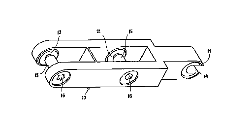
Fig. 1 shows a preferred embodiment of a building element 10,
intended to be connected with other elements by a connecting
means according to the invention. In this case, the building
element has connecting means comprising a first coupling part
11 and two other coupling parts 12 and 13. It is evident to a
skilled person that the number of coupling parts on a building
element is immaterial; however, each building element must at
least include a first coupling part and/or a second coupling
part. Thus, building elements are conceivable which comprise
only for example a first coupling
22903-377

_ 4 _ ~ ps~ ~K~0/000~
part, since this element may thus be coupled with building
elements comprising at least one second coupling part. The
first coupling part 11 comprises a claw-shaped jaw part
14, while the second coupling part 12 and 13 comprises a
bushing 15 and a clamping device 16.
Fig. 2 is a top view of the building element from Fig. 1.
The second coupling part is shown without bushings, and,
as will be seen, the second coupling part is formed with
two collars 20 which, in combination with an associated
cut 30 in the first coupling part (see Fig. 3), produces a
snap lock effect when two corresponding coupling means are
brought together. The snap lock effect may be generated in
that at least one of the corresponding coupling parts is
resilient, in this case the second coupling part, where
for example the beam areas 21 and 22 move apart when the
connecting means is engaged.
Fig. 3 shows a section through the building element from
Fig. 2. It appears that the first coupling part is pro-
vided with cuts 30 which are complementary to the collars
20 of the second coupling part. A clamping device may be
implemented by for example a screw whose head is concealed
in a recess 31 and whose outer threads fit with inner
threads 32 implemented in the building element. When the
screw, with abutment in the recess 31, is tightened in the
thread 32, the resilience in the second coupling part in
question is remove,d, which causes a first coupling engaged
with the second coupling part to be fixed. According to a
preferred embodiment the thread pitch is great, which
means that fixing can take place very rapidly without the
screw having to be rotated noticeably. The screw may also
be provided with a snap lock device on the shaft, which
fixes it in the building element when the second coupling
part has full resilience, i.e. that the screw cannot drop
out of the building element when loosened. In the loosened

~ ~0/09825 PCT/DK90/000~
- S %~ o ~
state, the outer threads of the screw may moreover be out
of engagement with the inner threads 32, so that in this
state disengagement is involved. It is evident to a
skilled person that the snap lock effect can also be pro-
vided in that the first coupling part is resilient insteadof the second coupling part.
Since, according to the invention, the connecting means
will typically be made of plastics, the clamping device -
with a view to avoiding overloading - may be operatively
connected with a disengagement device, so as to ensure
that the clamping device can l~i -1ly be tightened with a
predetermined torque. Such a disengagement device may
either be integrated in the clamping device or be inte-
grated in a clamping tool intended for the purpose. In thelatter case, the use of unauthorized clamping tools may be
prevented by forming the clamping device with a special
coupling means intended for coupling with a complementary
coupling means on the clamping tool.
Figs. 4 and 5 show some coupling possibilities between two
building elements of the type shown in Fig. l. A first
coupling part ll on a first building element 40 is caused
to engage a second coupling part 12 on a second building
element 41. In this state, the building elements will be
mutually rotatable around the clamping device 16. The ele-
ments may now be locked in a desired position by rotation
of the clamping de,vice 16. As appears, the clamping device
may be provided with a substantially pentagonal coupling
means, which provides a safeguard against the use of un-
authorized tools.
Fig. 6 shows an exploded projection of respective coupling
parts. A first coupling part 51 essentially corresponds to
the coupling part ll and has likewise a claw-shaped jaw
part 14. The first coupling part Sl is formed-with a de-

~ go~o9825 2~ 4 ~ ~ o ~ PCT/DK90/000~
pression or cut like the cut 30, but is here provided witha plurality of radially extending depressions 52. The se-
cond coupling part comprises several separate parts in
this embodiment. A separate part 54 is adapted to be
mounted in the building element 53 where it is retained.
The separate part 54 has a central hole 55 with threads to
receive a screw 16 which is likewise threaded. The part 54
has a plurality of resilient tongues 56 on its inwardly
directed end face, said tongues, in assembled state, co-
operating with the depressions 52 in the first couplingpart 51. The first and the second coupling part can hereby
rotate with respect to each other, the cooperating depres-
sions 52 and resilient tongues 56 providing a click func-
tion.
Fig. 7 shows a horizontal longitudinal section through a
building element in the alternative emb~i ent. It is
shown here how the two separate parts 54a and 54b are
firmly mounted in the building element. A screw 16a is
shown without threaded engagement with the treads in the
part 54a, and it is prevented from dropping out since a
jump in its outer diameter acts as a snap lock, as men-
tioned. A first coupling part can be coupled by the screw
16a with the shown coupling part since its jaws are here
free to perform the necessary elastic movement for the
coupling. A screw 16b is shown in engagement with the
corresponding threads in the separate part 54b, and the
outward elastic mo,vement is blocked in this state by the
parts of the building element adapted for this purpose, so
that coupling and particularly separation of assembled
building elements is prevented. When the screw 16 is
screwed into the threads in the separate part 54, clamping
between these parts is established, and this allows in
particular the unhindered mutual rotation of two assembled
building elements, while their separation is prevented, as
mentioned .

Representative Drawing
A single figure which represents the drawing illustrating the invention.
Administrative Status

2024-08-01:As part of the Next Generation Patents (NGP) transition, the Canadian Patents Database (CPD) now contains a more detailed Event History, which replicates the Event Log of our new back-office solution.

Please note that "Inactive:" events refers to events no longer in use in our new back-office solution.

For a clearer understanding of the status of the application/patent presented on this page, the site Disclaimer , as well as the definitions for Patent , Event History , Maintenance Fee  and Payment History  should be consulted.

Event History

Description Date
Inactive: Expired (new Act pat) 2010-02-23
Letter Sent 2008-03-04
Inactive: Multiple transfers 2007-12-13
Inactive: IPC from MCD 2006-03-11
Grant by Issuance 1998-05-19
Inactive: Application prosecuted on TS as of Log entry date 1998-03-17
Inactive: Status info is complete as of Log entry date 1998-03-17
Inactive: IPC removed 1998-02-27
Inactive: IPC assigned 1998-02-27
Inactive: First IPC assigned 1998-02-27
Inactive: Delete abandonment 1998-02-16
Deemed Abandoned - Conditions for Grant Determined Not Compliant 1997-10-15
Pre-grant 1997-10-02
Notice of Allowance is Issued 1997-04-15
Request for Examination Requirements Determined Compliant 1996-10-21
All Requirements for Examination Determined Compliant 1996-10-21
Application Published (Open to Public Inspection) 1990-08-25

Abandonment History

Abandonment Date Reason Reinstatement Date
1997-10-15

Maintenance Fee

The last payment was received on 1998-02-09

Note : If the full payment has not been received on or before the date indicated, a further fee may be required which may be one of the following

  • the reinstatement fee;
  • the late payment fee; or
  • additional fee to reverse deemed expiry.

Please refer to the CIPO Patent Fees web page to see all current fee amounts.

Fee History

Fee Type Anniversary Year Due Date Paid Date
Final fee - standard 1997-10-02
MF (application, 8th anniv.) - standard 08 1998-02-23 1998-02-09
MF (patent, 9th anniv.) - standard 1999-02-23 1999-02-04
MF (patent, 10th anniv.) - standard 2000-02-23 2000-01-19
MF (patent, 11th anniv.) - standard 2001-02-23 2001-01-18
MF (patent, 12th anniv.) - standard 2002-02-25 2002-01-17
MF (patent, 13th anniv.) - standard 2003-02-24 2003-01-17
MF (patent, 14th anniv.) - standard 2004-02-23 2003-12-22
MF (patent, 15th anniv.) - standard 2005-02-23 2005-01-06
MF (patent, 16th anniv.) - standard 2006-02-23 2006-01-05
MF (patent, 17th anniv.) - standard 2007-02-23 2007-01-08
Registration of a document 2007-12-13
MF (patent, 18th anniv.) - standard 2008-02-25 2008-01-07
MF (patent, 19th anniv.) - standard 2009-02-23 2009-01-13
Owners on Record

Note: Records showing the ownership history in alphabetical order.

Current Owners on Record
LEGO A/S
Past Owners on Record
FLEMMING HõJBERG OLSEN
Past Owners that do not appear in the "Owners on Record" listing will appear in other documentation within the application.
Documents

To view selected files, please enter reCAPTCHA code :


To view images, click a link in the Document Description column. To download the documents, select one or more checkboxes in the first column and then click the "Download Selected in PDF format (Zip Archive)" or the "Download Selected as Single PDF" button.

List of published and non-published patent-specific documents on the CPD .

If you have any difficulty accessing content, you can call the Client Service Centre at 1-866-997-1936 or send them an e-mail at CIPO Client Service Centre.


Document
Description 
Date
(yyyy-mm-dd) 
Number of pages   Size of Image (KB) 
Description 1994-02-26 7 286
Drawings 1994-02-26 4 87
Claims 1994-02-26 3 105
Abstract 1994-02-26 1 15
Cover Page 1994-02-26 1 15
Representative drawing 1998-05-05 1 6
Description 1997-04-15 7 290
Cover Page 1998-05-11 1 40
Abstract 1997-04-15 1 15
Courtesy - Certificate of registration (related document(s)) 2008-03-04 1 108
Fees 2016-03-16 1 30
Fees 1996-02-02 1 44
Fees 1995-02-01 1 63
Fees 1994-02-08 1 28
Fees 1993-02-04 1 32
Fees 1992-02-03 1 28
International preliminary examination report 1991-08-23 31 977
Prosecution correspondence 1997-08-15 1 19
PCT Correspondence 1991-10-18 1 35
Prosecution correspondence 1996-10-21 1 30
Prosecution correspondence 1997-10-02 1 39
Courtesy - Office Letter 1991-10-09 1 26
Prosecution correspondence 1996-12-04 1 26
Prosecution correspondence 1996-12-16 1 23
Examiner Requisition 1996-11-29 1 45
Courtesy - Office Letter 1996-11-07 2 56
Courtesy - Office Letter 1991-10-28 1 20