Note: Descriptions are shown in the official language in which they were submitted.
20~"~~~6
FOETAL PULSE OXZMETRY APPI~rR.A.TU:~ A3~iD METi30D OF USE
Background of the invention
This invention relates to an intrauterine pulse oximetry
apparatus and method fox measuring foetal oxygen saturation
during labour and delivery. The invention particularly relates
to placing the apparatus within a preferred region on the foetus .
A foetal pulse oximetry apparatus may include a sensor
attached to an electrical cable. The sensor, which contains a
light source and a light detector, is placed on the foetus. The
cable connects the sensor to a pulse oximeter. Light from the
light source is transmitted through the foetal tissue and
reflected back to the light detector. The amount of light
received by the light detector depends on characteristics of the
blood in the foetal tissue, among other things.
Foetal pulse oximetry sensors are not new. Some previous
apparatus were physically attached to the foetal skin by hooks,
spirals, suction, or glue. One example is the foetal pulse
CA 02047586 2000-12-28
oximetry sensor disclosed in PCT Publication No. WO
90/01293. These attachment means were invasive or potentially
harmful. Therefore the. apparatus were placed only in fetal
regions that the doctor or other user could reach with his or her
fingers, such as on the presenting part of the fetus or on the
fetus within the uterine region just beyond the cervix (the
"transcervical region").
The structure of previous apparatus did not permit safe and
accurate placement on the fetus in the region beyond the reach of
the user. In addition, nothing was known of fetal pulse
c:3racteristics in this region. Thus placement of the apparatus
beyond the presenting part or in the transcervical region was
considered undesirable.
Summarv of the Invention
Our tests have shown that fetal pulses are stronger in the
region on the fetus beyond the presenting part and beyond the
transcervical region. We call this fetal region the "preferred
region."' The present invention monitors pulses in the preferred
region.
In a vertex presentation (i.e. with the fetus descending
headfirst), cervical pressure on the presenting part creates
local edema (caput) which can suppress the fetal pulse and make
pulse oximetry readings unreliable. The amplitude of the pulse
in the presenting part also will change as the cervix dilates and
changes the local force on the vertex.
2
During the periodic contractions of the uterine wall,
additional local forces on the presenting part of the fetus are
exerted actively by the cervix and passively by the pelvic bones.
These transient local forces may further affect pulse amplitude.
Thus, obtaining strong and consistent pulses throughout labor and
delivery may be difficult.
The readings also may be affected by fetal hair. Depending
on its color and amount, hair attenuai~es the light to various
extents. Flair also may cause light to be shunted from the light
source to the light detector, which adversely affects 'the
measurement.
The present invention overcomes some of the shortcomings of
previous fetal pulse oximetry apparatus and their placement
methods, It provides an apparatus and a method of placing it in
the preferred region, ioe, on the fetus beyond the presenting
part and beyond the transcez-yical region. Pulse amplitudes in
the preferred region are riot affected by caput. They are less
affected by cervical and pelvic bone forces than in the
presenting part or the transcervical region. Since there is less
hair (or even no hair] in the preferred region, the light
transmission to and from the fetal tissue will be less attenuated
and less susceptible to shunting. The apparatus and method allow
the user to place the sensor without damaging the sensitive fetal
eyes and fontanelles.
The preferred embodiment of the apparatus provides an
3
~~~~~~6
electrical cable having a stiffer part adjacent to the sensor.
This stiff part of the cable can be used to guide the sensor into
position. The stiff part of the oable is rigid enough to be
guided through the vagina and cervix without an introducer. It
is flexible enough to yield when the sensor encounters an
obstruction such as the uterine wall. With the sensor in
position, the stiff part of the cable bends around the fetal head
and conforms to the mother°s pelvic curve. This conformance
allows prolonged application of the sensor without discomfort to
the mother.
The stiff part of the cable has calibrated visual markings
and one or more tactile markings (ridges). The visual markings
are particular distances from the leading edge of the sensor.
The ridge is located at a position approximating the distance
from the vertex of the fetal head to a site well within the
preferred region on a fetus at term. The ridge may coincide with
one of the visual markings.
Devices inserted into the mother°s uterus must be sterile to
avoid infection. As in prior art, the user must manipulate the
apparatus within the vagina to place the sensor. If a prior~art
device failed, the user would have to perform an additional
vaginal examination to remove it. It would have to be sterilized
before being reapplied. It also could be reapplied only with an
introducer. If sterilizing were impractical, a new device would
have to be used.
4
~0~~~~~
The current apparatus overcomes these limitations. If the
sensor does not perform properly in its initial placement, the
user can grasp the exposed stiff part of the cable and insert or
withdraw it a small amount, for example 1 cm., as indicated by
the visual markings. This action will reposition the sensor on a
new site within the preferred region of. the fetal head without
removing the sensor from the uterus.
The method of using the apparatus has many advantages over
prior art. It does not reintroduce anything into the vagina.
Pulse oximetry readings thus can be taken without re-sterilizing
the apparatus, outfitting it with an introduces, or using a new
apparatus. The method typically is painless for the mother: it
does not require uncomfortable manipulation of the apparatus
inside the vagina. The method can be repeated during labor as
necessary, for optimal sensor performance.
kith the stiff part of the cable the user also can monitor
the station of the fetal head (i.e, the position of the fetal
head within the mother's pelvisy. Fetal head station is
important to evaluate the progression of labor. It is determined
by internal examination, which assesses the position of the fetal
head relative to the pelvic spines. The apparatus and method of
the current invention permit the user t~ continuously assess this
position without frequent repeated internal examinations.
As. the fetal head descends during labor, the sensor descends
with it. If the user notes the station of the fetal head when
the sensor is initially placed, the station c;an be correlated
with the amount of the stiff part of the cable protruding from
the vagina. The visual markings indicate hour much of the stiff
part is exposed. The exposed stiff part of the cable will
represent the station of the fetal head.
one skilled in the art will recognize that the apparatus
could operate as a fetal station indicator without using the
oximetry sensor so long as some means of placing the inner end of
the tube against the fetus within a preselected region is
provided. .~ trailer extending from the inner end of the
indicator through the mother's vagina would have visual markings
correlating to the station of the petal head.
The objects of the invention are as followse
To obtain improved pulse oximetry readings by measuring
fetal oxygen saturation in a region with stronger pulses.
To obtain improved pulse oximetry readings by measuring
fetal oxygen saturation in a region less affected by caput,
cervical pressures, and hair.
To obtain the improved readings safely, that is without
injuring the fetus or the mother.
To obtain the readings comfortably for the mother.
To allow prolonged yet comfortable and accurate monitoring
of the fetus.
To orient the apparatus effectively without seeing or
ultimately feeling the sensor, since the sensor's target is
6
~~4"~~86
beyond the reach of the user.
To reposition the sensor in the preferrecl region without
withdrawing the apparatus from the uterus.
When repositioning, to avoid re-sterilizing the apparatus,
when repositioning, to avoid using an introducer.
When repositioning, to avoid using a new (sterile)
apparatus.
When repositioning, to avoid causing discomfort to the
mother.
To determine the station of the fetal head during labor
without repeated internal examinations.
Hrief Description of the Drawinas
In all drawings, like parts are designated by like reference
numbers.
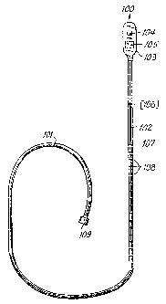
Fig. 1 is an overall view of the apparatus of the invention.
Fig. 2 is a view of the active side of the sensor, showing
the light source and light detector.
Fig. 3 is a view of the inactive side of the sensor.
Fig. 4 is a cross-section of the sensor.
Figs. 5 through ? show the method of the invention. Fig. 5
shows the user inserting the apparatus into the vagina. Fig. 6
shows the user°s hand guiding the sensor to the preferred region.
Fig. 7 shows the sensor in place in the preferred region after
the user removed his or her hand.
Detailed Description of the ~znbodiments
"1
~04~~~~
The preferred embodiment of the apparatus is shown in Fig.
1. Apparatus 100 includes a sensor 1C13 and an electrical cable
101 with a connector 109. The electrical cable has a stiffer
part 102 adjacent to the sensor. The stiffer part of the cable
is rigid enough to be guided unsupported through the vagina and
cervix and flexible enough to yield when the sensor encounters an
obstruction such as the uterine wall.
In the preferred embodiment, a part of the cable is
stiffened by enclosing it in a pl-astic tube. For example, the
cable can be surrounded by shrink-tubing of an inner diameter of
0.?5 cm and an outer diameter of 0.41 cm. To allow
repositioning, this tube must be long enough, preferably 30 cm,
to extend from the vagina when the sensor is in the preferred
region.
The sensor 103 has one or more emitters (the light
source(s)) 104 and detectors (the light detector(s)) 105. The
preferred embodiment has two emitters and a detector on one side,
the active side, as shown in Fig. ~. In the preferred
embodiment, the other or inactive side of the sensor has at least
one tactile marking such as a bump or an indentation 120, as
shown in Figs. 3 and 4. This marking helps the user properly
orient the apparatus while inserting it int~ the vagina and
through the cervix. The leading edge 110 of the sensor 103 is
bevelled, as shown in Fig. 4, to facilitate introduction later in
labor through a cervix that may be well-applied tc (snug against)
8
2(~~"~~~~
the fetal presenting part 204.
The preferred embodiment of the cable 100 has a series of
regularly spaced markings 108. These markings provide a visual
indication of the insertion depth of t:he sensor in the mc~her's
vagina. In addition, a ridge 107 is l:ormed on the cable at a
predetermined distance from the leading edge 110 of the sensor
103. The sensor is introduced until the ridge 107 is at the
sagittal suture of the fetal head. The sensor is then in the
preferred region 205.
The method of using the apparatus is as follows. The user
determines the location of the fetal back and the height and
orientation of the fetal head by abdominal examination. The user
then makes a vaginal assessment of cervical status using the
Bishop's score. This vaginal examination may also precisely
confirm the position of the fetal head.
With the examining fingers 201 already in the vagina 202 and
at the posterior cervix 203, the user grasps the apparatus 100 by
the stiff part of the cable 102 with the other hand 200. The
sensor 103 is then inserted into the vagina with the active side
up. Tt is then threaded up between the index and middle fingers
201 of the examining hand. The finger-tips of that hand feel far
the bump or indentation 120 on the inactive side of the sensor
103. See Figs. 5, 6, and 7.
The fingers 201 of the examining hand stretch the posterior
cervix 203 to make room for the sensor. The user further
9
2~4'~~~6
advances the sensor into the uterus past the presenting part and
past the transcervical region. The sensor is then in the
preferred region. For a fetus at term, the ridge l07 will be
flush with the presenting part 20~b when the sensor is in the
preferred region, as in Fig, 6. The user then removes his or her
fingers from the vagina, leaving the sensor 100 in place, as in
Fig. 7. If the readings from the initial placement are
unsatisfactory, the sensor can be repositioned by slightly
withdrawing or further inserting the stiff part of the cable 102.
The preferred method of constructing the cable°s features is
as follows. Plastic tubing, such as polyolefin made by Rayehem,
is heat-shrunk over the area of the cable to become the stiff
part. This first layer stiffens the cable. Regularly spaced
markings are then drawn on the plastic tubing. In the preferred
embodiment the markings are 1 cat apart, although any convenient
marking scale can be used. The markings can take various forms,
such as colors, characters, or numbers.
The ridge is formed by heat--shrinking a short segment of
plastic tubing around this sable assembly at an appropriate
location. Tn the preferred embodiment, the ridge is 15 cm from
the leading edge of the sensor. That is the approximate distance
from the vertex of a molded fetal head at term to the preferred
region for the sensor. The ridge may be used as a visual marking
as well by making it a different color from that of the cable.
After the ridge and the visual markings are applied to the
Z~~'~~~6
cable, a clear plastic sheath is heat-shrunk over the cable
assembly. The sheath smooths the edges o.f the ridge and protects
the visual markings. It also further stiffens the cable.
m