Language selection

Search

Patent 2047797 Summary

Third-party information liability

Some of the information on this Web page has been provided by external sources. The Government of Canada is not responsible for the accuracy, reliability or currency of the information supplied by external sources. Users wishing to rely upon this information should consult directly with the source of the information. Content provided by external sources is not subject to official languages, privacy and accessibility requirements.

Claims and Abstract availability

Any discrepancies in the text and image of the Claims and Abstract are due to differing posting times. Text of the Claims and Abstract are posted:

  • At the time the application is open to public inspection;
  • At the time of issue of the patent (grant).
(12) Patent Application: (11) CA 2047797
(54) English Title: CAULK AND GLAZING TOOL
(54) French Title: OUTIL A ETENDRE LE MASTIC ET AUTRES PRODUITS D'ETANCHEITE
Status: Deemed Abandoned and Beyond the Period of Reinstatement - Pending Response to Notice of Disregarded Communication
Bibliographic Data
(51) International Patent Classification (IPC):
  • E04F 21/165 (2006.01)
  • A47L 17/06 (2006.01)
  • E04F 21/16 (2006.01)
  • E04F 21/32 (2006.01)
(72) Inventors :
  • LEMASTER, GUY N. (United States of America)
(73) Owners :
  • GUY N. LEMASTER
(71) Applicants :
(74) Agent: MARKS & CLERK
(74) Associate agent:
(45) Issued:
(22) Filed Date: 1991-07-24
(41) Open to Public Inspection: 1992-01-27
Examination requested: 1996-10-17
Availability of licence: N/A
Dedicated to the Public: N/A
(25) Language of filing: English

Patent Cooperation Treaty (PCT): No

(30) Application Priority Data:
Application No. Country/Territory Date
07/558,310 (United States of America) 1990-07-26

Abstracts

English Abstract


ABSTRACT OF THE DISCLOSURE
A glazing tool which has a handle plate to be gripped
between the thumb and forefinger of an operator. Two spaced
trim blades have runner edges disposed at an angle to handle
plates to trim the bead of glazing material. These runner edges
angle toward the distal end of the back plate where a bead
contact blade is disposed transversely of the runner edges.
Perforate side wings proximal to the bead contact blade rise
upwardly and outwardly of the trim blades to guide trimmed glaze
material away from the tool.


Claims

Note: Claims are shown in the official language in which they were submitted.

THE EMBODIMENTS OF THE INVENTION IN WHICH AN EXCLUSIVE
PROPERTY OR PRIVILEGE IS CLAIMED ARE DEFINED AS FOLLOWS:
1.
A tool for smoothing and shaping glazing material in
a trowelling operation on windows which comprises:
(a) a flat handle plate for manual gripping lying in
a first plane and having a distal and a proximal end,
(b) spaced shoe plates depending from each side of
said handle plate having spaced, elongate bottom runner edges
extending rearwardly from the distal end of said handle plate
and disposed at a 30° to 45° angle to the plane of said handle
plate to trim glazing material at the runner edges,
(c) a smoothing blade transverse of said handle plate
at the distal end of said handle plate essentially at the apex
of the angle between the plane of the handle plate and the
runner edges of the shoe plates, and
(d) spaced side wings flaring upwardly and outwardly
from each side of said smoothing blade above the runner edges
of said shoe plates and extending rearwardly toward the proximal
end of the handle plate, said side wings having elongate
perforations above said runner edges within the confines of
said wings to feed excess trimmed glazing material away from
the smoothing blade.
2.
A tool as defined in claim 1 in which the runner edges
of said spaced shoe plates lie in spaced planes diverging from
the distal end of the handle plate toward the proximal end and
sid perforations extend above and in the same direction as said
runner edges.

Description

Note: Descriptions are shown in the official language in which they were submitted.


2~7~97
Title
CAULK A~D GL~ZI~G TOOL
Field of Invention
Tools for shaping and smoothing putty and caulk in
ninety-degree corners.
Background and Objects of the Invention
In the application of a putty or caulking bead at the
juncture of an angularly disposed pair of walls or against a
glass pane, considerable difficulty is encountered by the
craftsman as well as the unskilled in shaping, packing and
troweling the mastic caulking compounds to form a straight and
clearly defined bead. The problem largely arises due to the
fact the initial extrusion of caulk or putty as from acollapsible
tube or a caulking gun or as applied by hand is irregular in
shape and generally involves an excess of caulk. The removal
of the excess by wiping or scooping with a putty knife or similar
tool is often accompanied by disruption of the desired applied
bead in the juncture being caulked. Various kinds of corner-
finishing tools are known from U.S. Patent Nos. 2,193,390;
2,271,285; 3,087,654 and 3,846,060. These, however, have not
been found capable of troweling a bead in a right-angle corner
and displacing during the troweling any excess cauIk to locations
where it can be easily removed, it being the primary object of
this invention to do so.

2~7797
Another object of this invention has been theprovision
of a tool that may be accurately aligned betwe~n a pair of
right-angle surfaces andin movement longitudinal of the juncture
therebetween be smoothly guided and supported thereby.
Still another object is the provision in such a
troweling tool of resilient scraping and troweling means whereby
pressure is applied to the mastic caulk during troweling to
insure filling and to expel entrapped air or gas bubbles.
An objec~ of the present invention is to provide an
improved cornering tool which will smooth and trlm putty or
caulk in a 90 crevice while removing excess material leaving
the 45 strip intact and pressed firmly in place.
Caulk or putty usually has an oil binder which will
cling to wood and glass when pressed firmly into the 90~ corner
intended for it. The glazing tool of the present invention is
easily manually manipulated to be dxawn along the applied putty
to angle it properly and leav~ a smooth surface.
Objects and features of the invention will be apparent
in the following description and claims in which the invention
is set forth together with details to enable persons skilled
in the art to practice the invention all in connection with the
best mode presently contemplated for the invention.
--2--

2~7~
Brief Description of the Dra~ngs
DRAWI~GS accomp~ny the disclosure and the various
views thereof may be briefly described as:
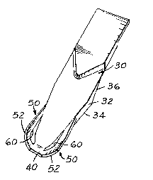
FIG~ 1, a perspective view of the smoothing tool
angled in a work position.
FIG. 2, a view of the smoothing tool as applied to a
glazing function.
FIG. 3, a sectional view on line 3-3 of FIG~ 2.
FIG~ 4, a plan view of the toolO
FIG. 5, a side elevation o the tool.
FIG. 6, a top view of the tool on arrow 6 o FIG. 5.
FIG. 7, a section on line 7--7 of FIG. 5.
Detailed Description of the Invention
and the Nanner and Pro~ess of Usinq It
With reference to the drawings, the glazing tool is
illustrated in FIG. 2 held between the thumb and forefinger and
being applied to a strip of putty 20 between a sash piece 22 and
a glass pane 24. A handle or back plate portion 30 has, on
each side, depending shoe plates 32. These shoe plates each have
a runner edge 34 disposed at an angle to the plane of the back
plate 30, the angle being 30 to 45. The trailing edges 36 of .
the runners rise to the back plate 30. These shoe plates 32
are cutter blades preferably in spaced planes which converge at
an apex of the shoe plates toward khe forward distal end o the
back plate to form a blade contact end. The blade end 40 of
the back plate will be in direct contact with the bead of putty
20 when being drawn along the bead.
--3--
`~ ` .` ." ' '' ' ~ . ' ,' ' ' '
., . ~ , . . . ~ . . .

2~77~7
On each side of the blade end of the back plate 30
and rising from the shoe plates 32 are angled wings 50 each
comprising a narrow lead piece 52 which rises from the plane of
the runner edges 34 and flares upwardly and outwardly as shown
best in FIGS. 4 and 5. Integral with these lead pieces 52 are
rearwardly extending connectors 54 which extend to the sides
of the back plate 30. Triangular apertures 60 thus are formed
by the wings 50 open to ~he outside of the shoe plates 32.
As illustrated in FIG. 2, the tool is grasped between
the thumb and forefinger and drawn rearwardly while being pressed
down over a bead of putty 20. The runners on the blades 34
will trim the sides of the bead and any excess trim will feed out
of the openings 60 away from the tool where it can be readily
recovered and restored to the basic supply of putty.

Representative Drawing
A single figure which represents the drawing illustrating the invention.
Administrative Status

2024-08-01:As part of the Next Generation Patents (NGP) transition, the Canadian Patents Database (CPD) now contains a more detailed Event History, which replicates the Event Log of our new back-office solution.

Please note that "Inactive:" events refers to events no longer in use in our new back-office solution.

For a clearer understanding of the status of the application/patent presented on this page, the site Disclaimer , as well as the definitions for Patent , Event History , Maintenance Fee  and Payment History  should be consulted.

Event History

Description Date
Inactive: IPC from MCD 2006-03-11
Application Not Reinstated by Deadline 1999-07-26
Time Limit for Reversal Expired 1999-07-26
Deemed Abandoned - Failure to Respond to Maintenance Fee Notice 1998-07-24
Letter Sent 1997-10-03
Reinstatement Requirements Deemed Compliant for All Abandonment Reasons 1997-09-08
Deemed Abandoned - Failure to Respond to Maintenance Fee Notice 1997-07-24
Request for Examination Requirements Determined Compliant 1996-10-17
All Requirements for Examination Determined Compliant 1996-10-17
Application Published (Open to Public Inspection) 1992-01-27

Abandonment History

Abandonment Date Reason Reinstatement Date
1998-07-24
1997-07-24

Maintenance Fee

The last payment was received on 1997-09-08

Note : If the full payment has not been received on or before the date indicated, a further fee may be required which may be one of the following

  • the reinstatement fee;
  • the late payment fee; or
  • additional fee to reverse deemed expiry.

Please refer to the CIPO Patent Fees web page to see all current fee amounts.

Fee History

Fee Type Anniversary Year Due Date Paid Date
Reinstatement 1997-09-08
MF (application, 6th anniv.) - small 06 1997-07-24 1997-09-08
Owners on Record

Note: Records showing the ownership history in alphabetical order.

Current Owners on Record
GUY N. LEMASTER
Past Owners on Record
None
Past Owners that do not appear in the "Owners on Record" listing will appear in other documentation within the application.
Documents

To view selected files, please enter reCAPTCHA code :


To view images, click a link in the Document Description column. To download the documents, select one or more checkboxes in the first column and then click the "Download Selected in PDF format (Zip Archive)" or the "Download Selected as Single PDF" button.

List of published and non-published patent-specific documents on the CPD .

If you have any difficulty accessing content, you can call the Client Service Centre at 1-866-997-1936 or send them an e-mail at CIPO Client Service Centre.


Document
Description 
Date
(yyyy-mm-dd) 
Number of pages   Size of Image (KB) 
Drawings 1992-01-27 1 36
Claims 1992-01-27 1 36
Abstract 1992-01-27 1 16
Cover Page 1992-01-27 1 17
Descriptions 1992-01-27 4 118
Representative drawing 1999-07-06 1 5
Courtesy - Abandonment Letter (Maintenance Fee) 1997-09-30 1 188
Notice of Reinstatement 1997-10-03 1 172
Courtesy - Abandonment Letter (Maintenance Fee) 1998-08-24 1 189
Fees 1996-06-18 1 53
Fees 1995-06-16 1 41
Fees 1994-06-16 1 75
Fees 1993-07-06 1 41