Language selection

Search

Patent 2047824 Summary

Third-party information liability

Some of the information on this Web page has been provided by external sources. The Government of Canada is not responsible for the accuracy, reliability or currency of the information supplied by external sources. Users wishing to rely upon this information should consult directly with the source of the information. Content provided by external sources is not subject to official languages, privacy and accessibility requirements.

Claims and Abstract availability

Any discrepancies in the text and image of the Claims and Abstract are due to differing posting times. Text of the Claims and Abstract are posted:

  • At the time the application is open to public inspection;
  • At the time of issue of the patent (grant).
(12) Patent Application: (11) CA 2047824
(54) English Title: CRANKCASE HEATER CONTROL FOR HERMETIC REFRIGERANT COMPRESSORS
(54) French Title: DISPOSITIF DE COMMANDE/REGULATION DE CHAUFFE-CARTER POUR COMPRESSEUR FRIGORIFIQUE HERMETIQUE
Status: Deemed Abandoned and Beyond the Period of Reinstatement - Pending Response to Notice of Disregarded Communication
Bibliographic Data
(51) International Patent Classification (IPC):
  • F16N 39/04 (2006.01)
  • F04B 39/00 (2006.01)
  • F25B 1/02 (2006.01)
  • F25B 31/00 (2006.01)
  • F25B 43/02 (2006.01)
(72) Inventors :
  • DUDLEY, KEVIN F. (United States of America)
(73) Owners :
  • CARRIER CORPORATION
(71) Applicants :
  • CARRIER CORPORATION (United States of America)
(74) Agent: GOWLING WLG (CANADA) LLP
(74) Associate agent:
(45) Issued:
(22) Filed Date: 1991-07-24
(41) Open to Public Inspection: 1992-03-22
Availability of licence: N/A
Dedicated to the Public: N/A
(25) Language of filing: English

Patent Cooperation Treaty (PCT): No

(30) Application Priority Data:
Application No. Country/Territory Date
586,122 (United States of America) 1990-09-21

Abstracts

English Abstract


CRANKCASE HEATER CONTROL FOR HERMETIC REFRIGERANT COMPRESSORS
Abstract Of The Disclosure
The temperature is sensed at the compressor, indoor coil and
outdoors. The sensed temperatures are compared and if the
compressor temperature is not a specified amount higher than
the lower of the other two sensed temperatures, then the
crankcase heater is energized. When the compressor
temperature rises to or is a specified amount above the lower
of the other two temperatures, the crankcase heater is
deenergized.


Claims

Note: Claims are shown in the official language in which they were submitted.

CLAIMS
What is claimed is:
1. In a refrigeration system (10)serially
including a hermetic compressor (12) having a crankcase
heater (20), an outdoor coil (14), an expansion device (16),
and an indoor coil (18), crankcase heater control means
characterized by first temperature sensing means for sensing
a temperature indicative of outdoor temperature, second
temperature sensing means (118) for sensing a temperature
indicative of indoor coil temperature, third temperature
sensing means (112) for sensing a temperature indicative of
compressor temperature, and controller means (100)
operatively connected to said first, second and third
temperature sensing means and said crankcase heater for
comparing said temperatures sensed by said first, second and
third temperature sensing means when said compressor is
deenergized and for energizing said crankcase heater when
said temperature sensed by said third temperature sensing
means is less than a predetermined amount above the lower of
said temperatures sensed by said first and second temperature
sensing means and for deenergizing said crankcase heater when
said temperature sensed by said third temperature sensing
means is more than a second predetermined amount above the
lower of said temperatures sensed by said first and second
temperature sensing means.
2. The crankcase heater control means of claim 1
wherein said predetermined amount is 5 to 10 F°.

Description

Note: Descriptions are shown in the official language in which they were submitted.


2 ~
CRANKCASE HEATER CONTROL FOR HERMETIC REFRIGERANT COMPRESSORS
There is an affinity between the refrigerants and lubricants
used in refrigeration systems. As a result, it is normal for
some refrigerant to be present in the oil and for some oil to
be present in the refrigerant. When the hermetic comprassor
is shut off, refrigerant in the system tends to migrate and
condense. Since the ~ompressor is often at a low point in
the system there is a tendency for the refrigerant to colleck
there diluting thP oil in the sump and posing the risk of a
flooded start due to the presence of liquid refrigerant.
Crankcase heaters are designed to keep refrig~rant ~rom
migrating into the crankcase or sump of a hermetic compressor
durin~ an off cycle. Tha crankcase heaters are normally
energized continuously even though they are only effective
paxt of the time.
The present invention provides a way of energizing the
crankcase heater only when needed thereby reducing the ener~y
consumed by the heater. This is achievsd by controlling the
crankcase heater relative to sensed temperatures so that
migration to and condensation in the sump is at least reduced
if not eliminated.
It is an object of this invention to prevent refrigerant
migration to the sump o~ a hermetic compressor.
It is another object of this invention to control crankcase
heat in a hermetic compressor.
It is a further ob;ect of this invention to reduce the amount
of enargy required by a crankcase heater. These objects, and
others as well become apparent hereinafter, are accomplished
by th~ present invention~

2 ~78~
~asically, temperature is sensed at the compressor, the
indoor coil and outdoorsO The sensed temperatures are
compared and if the compressor temperature i~ not a specified
a~ount higher than the lower of the other two sensed
temperatures, then the crankcase heater is enargized. When
the compressor temperature rises to or is a specified amount
ahove the lower of the other two temperatures then the
crankcase heater is deenergized.
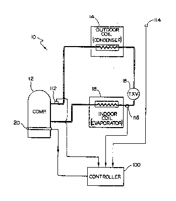
The Figure is a schematic representation of a closed
re~ri~eration system and its controls for regulating the
cr~llkcase heater.
In the Figure the numeral 12 generally designates a hermetic
compressor in a closed refrigeration system 10 configured as
a hea~ pump in the cooling mode. Starting with compressor
12, the system serially includes outdoor coil or condenser
14, thermal expansion device, TXV, 16 and indoor coil or
evaporator 18. The compressor 12 and indoor coil 18 are
located inside of the house or building being cooled and TXV
16 is either inside of the house or in close proximity
~hQreto~ In the operation of system 10, hot, high pressure
r~rigerant gas from compressor 12 is supplied to condenser
14 where the refrigerant gas condenses to a liquid which is
s~pplied to TXV 16. TX~ 16 causes a pressure drop and
partial flashing of the liquid refrigerant passing
thax~th~ough. The liquid refrigerant supplied to evaporator
lB ev~poratas to cool the house or building and the resultant
~eous re~rigerant is supplied to compressor 12 to complete
~ha cycle.
Tha system described above is conventional and to prevent the
~igration of refrigerant to compressor 12, a crankcase heater
would conventionally be provided. The crankcase heater would

2 ~ 2 ~
be run continuously or responsive to the oil temperature.
While such operation is effective, it can be waste*ul of
energy.
According to the teachings of the present invention, the
refrigerant temperature is sensed at the discharge of the
compressor 12 by sensor 112 and at the inlet side of the
evaporator 18 by sensor 118. Add.itionally, the outside or
ambient air temperature is sensed by sensor 114. Sensors
112, 114 and 118 are connected to controller 100 so as to
provida sensed temperature information thereto. Controller
100, typically, will be a part of a microprocessor
controlling system 10.
Compressor 12 is provided with a crankcase heater 20 which
may be of the band t~pe which is placed around the shell of
compressor 12 in the region of the oil ~ump, as illustrated,
or may be of the type which penetrates the shell of
compressor 12 and extends into the oil sump. Unlike
conventional crankcase heaters which are either on whenever
the compressor is not running, or are on responsive to oil
sump temperature, the present invention has crankcase heater
20 under the control of controller 100. Controller 100
activates crankcase heater 20 responsive to the temperatures
sensed b~ sensors 112, 114 and 118. Speci~ically, the
temperature sensed at the compressor discharge by sensor 112,
when compressor 12 is shut off, is maintained within a
predetermined temperature range above the lower of the
temperatures sensed by sensors 114 and 118 by energizing
crankcase heater 20. A preferred temperature range is 5 to
10 F above the lower of the temperatures sensed by sensors
114 and 118. When the temperature sensed at the compressor
discharge by sensor 112 exceeds the lower of the temperatures

2 ~
sensed by sensors 114 and 118 crankcase heater is deenergized
or remains unenergi~ed.
From the foregoing it should be clear that, in the present
invention, the crankcase heater 20 is only energized when
conditions favor refrigerant migration into the compressor 12
but that crankcase heater 20 is deenergized the rest of the
time which results in energy savings for the system.
Although a preferred embodiment of the present invention has
been described and illustrated, other changes will occur to
those skilled in the art. ~or example, both crankcase heater
20 and sensor 112 may be located in the sump of the
compressor 12 so as to be able to directly heat the oil and
directly sense the temperature of the oil.

Representative Drawing
A single figure which represents the drawing illustrating the invention.
Administrative Status

2024-08-01:As part of the Next Generation Patents (NGP) transition, the Canadian Patents Database (CPD) now contains a more detailed Event History, which replicates the Event Log of our new back-office solution.

Please note that "Inactive:" events refers to events no longer in use in our new back-office solution.

For a clearer understanding of the status of the application/patent presented on this page, the site Disclaimer , as well as the definitions for Patent , Event History , Maintenance Fee  and Payment History  should be consulted.

Event History

Description Date
Inactive: IPC from MCD 2006-03-11
Application Not Reinstated by Deadline 1996-01-24
Time Limit for Reversal Expired 1996-01-24
Inactive: Adhoc Request Documented 1995-07-24
Deemed Abandoned - Failure to Respond to Maintenance Fee Notice 1995-07-24
Application Published (Open to Public Inspection) 1992-03-22

Abandonment History

Abandonment Date Reason Reinstatement Date
1995-07-24
Owners on Record

Note: Records showing the ownership history in alphabetical order.

Current Owners on Record
CARRIER CORPORATION
Past Owners on Record
KEVIN F. DUDLEY
Past Owners that do not appear in the "Owners on Record" listing will appear in other documentation within the application.
Documents

To view selected files, please enter reCAPTCHA code :


To view images, click a link in the Document Description column. To download the documents, select one or more checkboxes in the first column and then click the "Download Selected in PDF format (Zip Archive)" or the "Download Selected as Single PDF" button.

List of published and non-published patent-specific documents on the CPD .

If you have any difficulty accessing content, you can call the Client Service Centre at 1-866-997-1936 or send them an e-mail at CIPO Client Service Centre.


Document
Description 
Date
(yyyy-mm-dd) 
Number of pages   Size of Image (KB) 
Abstract 1992-03-21 1 16
Claims 1992-03-21 1 37
Drawings 1992-03-21 1 24
Descriptions 1992-03-21 4 143
Representative drawing 1999-07-06 1 12
Fees 1994-06-19 1 98
Fees 1993-06-08 1 99