Language selection

Search

Patent 2048176 Summary

Third-party information liability

Some of the information on this Web page has been provided by external sources. The Government of Canada is not responsible for the accuracy, reliability or currency of the information supplied by external sources. Users wishing to rely upon this information should consult directly with the source of the information. Content provided by external sources is not subject to official languages, privacy and accessibility requirements.

Claims and Abstract availability

Any discrepancies in the text and image of the Claims and Abstract are due to differing posting times. Text of the Claims and Abstract are posted:

  • At the time the application is open to public inspection;
  • At the time of issue of the patent (grant).
(12) Patent Application: (11) CA 2048176
(54) English Title: PORTABLE EQUIPOTENTIAL PLANE FOR STRAY VOLTAGE REDUCTION
(54) French Title: NATTES PORTATIVES ATTENUANT LES TENSIONS ELECTRIQUES VAGABONDES
Status: Deemed Abandoned and Beyond the Period of Reinstatement - Pending Response to Notice of Disregarded Communication
Bibliographic Data
Abstracts

English Abstract


Abstract
There is disclosed a passive stray voltage reduction device
comprising a wire-mesh inserted in a rubber or plastic mat.The
wire-mesh is connected to a conducting object,the conducting
object being in contact with all metallic structure which an animal
might contact.
Those mats are fixed under the animals (for examples, cows,
pigs,...).
The device is used to reduce stray voltages in grounded farm
equipment to reduce harm to farm animals.


Claims

Note: Claims are shown in the official language in which they were submitted.

The embodiments of the invention in which an exclusive
property or privilege is claimed are defined as follows:
1. A portable equipotential plane inserted in a rubber or
plastic mat.
2. The device according to claim 1,wherein said equipoten-
tial plane is able to reduce or eliminate parasitic or stray
voltages.
3. The device according to claim 1, wherein said equipotential
plane is made of metal wires connected together and spaced
not more than 2 inches apart. (e.g.,wire-mesh).
4. The device according to claim 1, wherein said equipotential
plane can be made of a metal plate.
5. The device according to claim 1 must be covering the
major part of the mat.
6. The device according to claim 1, wherein the said mat is
made of rubber or plastic.
7. The device according to claim 1 must be connected to all
conductive objects which the animal might contact.
8. The device according to claim 1, wherein said equipotential
plane is electrically conductive.

Description

Note: Descriptions are shown in the official language in which they were submitted.


The present invention relates to an eguipotential plane for
parasitic or stray voltage reduction.
Stray or parasitic voltage is a small voltage that can be
mesured between two possible contact points, an electrically
grounded object and a ground reference.
When high voltage electrical equipment, such as distribution
transformers, are connected to the ground, the ground may offer
resistance causing the connection to the ground to have an
electrical potential above or below normal ground reference. The
same e~fect can be noticed even with medium voltage electrical
equipment such as electric motors used in farm machinery (e.g.
millcing machines). In this case, objects which are connected to
the same ground as the high or medium voltage electrical
equipment will have a ground reference which strays from normal
ground reference.
The stray or parasitic voltages are generally alternating and lie
roughly in the range of O to 15 volts. When conductive farm
equipment is connected to the same ground as the high voltage
electrical equipment, a farm animal coming into contact with the

X~7
farm equipment may be subjerted to parasitic voltages harmrul to
the health and productivity of the animals. A more in
description of the problem may be found in US pat~ ,355,595.
Many possible solutions for detecting and reducing such
voltages have been proposed as indicated, ~or example, by an 9 o l ,~ Z
article authored in 1978 by William Fairbank et al and entitled
"Milking Parlor Metal Stmcture-To-Earth Voltages",and by
another article authored in 1978 by R.D. Appleman and entitled
"Neutral-To-Ground Voltage Problems With Dairy Cows" and also
by an article authored in 1979 by L.H. Soderholm and entitled
"Stray-Voltage Problems In Dairy Milking Parlors".
One solution which has been widely attempted is to electrically
bond all electrical units (e.g., motors and controls) and all
conductive components (e.g., pipes, feeders and stalls) of the
system directly back to the earth ground at the electrical service
entrance. This makes all electrical units and conductive
components reside at virtually the same voltage as the neutral
conductor but does not eliminate different voltages from the
various units and components to different earth points. Thus, the

voltage to earth from the neutral conductor and a connected
component at one earth location can be diff~rent from the voltage
to earth from the neutral conductor and a connected component at
another earth location because of the resistance of the earth
between grounding points.
The object of the invention is therefore to provide an
inexpensive portable equipotential plane which will substantially
reduce or eliminate the latter voltage dif~erentials.
According to the invention, there is a passive stray voltage
reduction device comprising an equipotential plane inserted in a
rubber or plastic mat. The equipotential plane or mat is layed
down on the floor under the animal and connected to all
conductive equipment near the animal.
If the mat and all conductive structures which the cow, for
example, might contact with her hooves and with different parts of
her body are at the same potential, stray current wili not flow
through the animal.
The invention will be better understood after the following

description of the pre~erred embod;ment with reference to the
drawings in which:
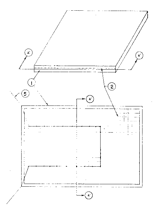
Fig. 1 shows a portable equipotential plane inserted in a rubber
or plastic ma~.
Fig.2 shows the animals on a portable equipotential plane.
As shown in Fig. 1, an equipotential plane 2 can be made with
metal wires connected together and spaced not more than 2 inches
apart (e.g.,wire-mesh). The equipotential plane can be made of a
metal plate also. The equipotential plane 2 is inserted in a rubber
or plastic mat 1.
One or many wires S, being in contact with the equipotential
plane 2, pertrude in order to be connected to any metallic structure
which the animal might contact.
As shown in Fig.2, the animals are standing on a portable
equipotential pLane 2 inserted into a mat 1. The equipotentic
plane 2 in the mat 1 is connected to the metallic stnlcture 3 which

the animals might contact. The metallic structure 3 is connected
to all metallic parts ~e.g., milk tube 7, rnetal water pipe 6, metal
stall pipes 8,...). An animal could, while standing on the floor 4
of
a farm building,in the absense of equipotential or mat 1, sense
stray voltages exceeding a given sensitivity threshold when it
comes into contact with the conductive object 3 carrying the stray
voltages. The mat 1 eliminates or reduces the stray voltage that
the animal does not perceive when in contact with object 3 and the
mat 1. The voltmeter 9 shows no voltage from pipe 6 to mat 1.
The invention operates in the immediate environment where
the suppression of stray voltage is required, such as in the stable
or in the piggery shown in Fig.2. The mats of the invention can
be installed in any farm building to prevent harm to the cmimals.
Installation of one or many equipotential mats according to the
diagrams can be affected without necessitating any changes to the
farm building in which those mats are installed.

Representative Drawing
A single figure which represents the drawing illustrating the invention.
Administrative Status

2024-08-01:As part of the Next Generation Patents (NGP) transition, the Canadian Patents Database (CPD) now contains a more detailed Event History, which replicates the Event Log of our new back-office solution.

Please note that "Inactive:" events refers to events no longer in use in our new back-office solution.

For a clearer understanding of the status of the application/patent presented on this page, the site Disclaimer , as well as the definitions for Patent , Event History , Maintenance Fee  and Payment History  should be consulted.

Event History

Description Date
Inactive: Inventor deleted 2002-05-06
Time Limit for Reversal Expired 1995-01-31
Application Not Reinstated by Deadline 1995-01-31
Deemed Abandoned - Failure to Respond to Maintenance Fee Notice 1994-08-01
Inactive: Adhoc Request Documented 1994-08-01
Application Published (Open to Public Inspection) 1993-01-31

Abandonment History

Abandonment Date Reason Reinstatement Date
1994-08-01
Owners on Record

Note: Records showing the ownership history in alphabetical order.

Current Owners on Record
CLAUDE MARCOUX
Past Owners on Record
None
Past Owners that do not appear in the "Owners on Record" listing will appear in other documentation within the application.
Documents

To view selected files, please enter reCAPTCHA code :


To view images, click a link in the Document Description column. To download the documents, select one or more checkboxes in the first column and then click the "Download Selected in PDF format (Zip Archive)" or the "Download Selected as Single PDF" button.

List of published and non-published patent-specific documents on the CPD .

If you have any difficulty accessing content, you can call the Client Service Centre at 1-866-997-1936 or send them an e-mail at CIPO Client Service Centre.


Document
Description 
Date
(yyyy-mm-dd) 
Number of pages   Size of Image (KB) 
Cover Page 1993-01-31 1 13
Abstract 1993-01-31 1 11
Claims 1993-01-31 1 21
Drawings 1993-01-31 2 43
Descriptions 1993-01-31 5 113
Representative drawing 1998-09-22 1 18
Fees 1992-07-14 1 33