Note: Descriptions are shown in the official language in which they were submitted.
203-28
~1159)
2~8~
1 APPARATUS AND METHOD FOR PRODUCING
BRAIDED SUTURE PRODUCTS
BACKGROUND OF_THE INVENTION
1. Field of_the_Invention
This invention relates to an improved apparatus
and method for braiding fine denier yarn~ into sutures for
surgical applications.
2. Description of the Prior Art
Braided products and apparatus for production o~
such products are well-known. However, for some time now,
braiding machines have been directed to production of
braided products of relatively bulky sizes for uses in
applications in packaging, window blind pulls, braided rope
or the lika. In essence, the applications for such braided
products are legion.
Typical of the braiding mechanisms used for such
product~ are disclosed in U.S. Patent Nos. 776,842 to
Horwood, 1,154,964 to Bentley, 1,285,451 to Stanton,
1,358,173 to Penso et al., 1,486,527 to Larkin, 1,785,683 to
Mallory, 2,079,836 to Brown et al., 2,200,323 to Barrans et
al., 2,452,136 to Marti, 4,158,984 to Griffiths, 4,304,169
to Cimprich et al., 4,333,380 to Kozlowski, 4,716,807 to
Fischer, 4,753,14g to Celani, 4,909,127 to Skelton ~t al.
and 4,922,798 to Ivsan. British Patent Publication No.
138,069 dated September 2, 1920 relates to improvements in
such braiding devices.
Sutures intended for the repair of body tissues
must meet certain requirements: they must be substantially
non-toxic, capable of being readily sterilized, they must
have good tensile strength and have acceptable knot tying
and knot-holding characteristics and if the sutures are of
'' . : ' ' : ' ' ~ ` ' ' '' ' .' ' :': .:. , . ' `
2 ~ 6 ~
1 the bio-abs~rbable variety, the bio absor]ption o~ the suture
must be closely controlled.
Sutures have been constructed from a wide variety
of materials including surgical gut, silk, cotton,
polyolefins such as polypropylene, polyamides, polyesters
such as polyethylene terephthalate, polygLycolic acid,
glyciolide-lactide copolymer, etc. Althou~j~h the optimum
structure of a suture is that of a mono~i]!ament, since
certain materials of construction would provide a stiff
monofilament suture lacking acceptable knot-tying and knot-
holding properties, sutures manufactured from such materials
have been provided as braided structures. Thus, ~or
example, sutures manufactured from silk, polyamide,
polyester and bio-absorbable glycolide-lacitide copolymer are
usually provided as multifilament braids.
Currently available braided sutllre products are
braidqd on conventional braider-carriers which travel around
the perimeter o~ the braider deck to result in a tubular
type braid with the yarns crossing over each other on the
surface o~ the braid. In the larger sizei~i;, e.g., 5/0 and
larger, the tubular braid, or sheath, is cionstructed a~out a
core structure which is fed through the center of the
braider. Known tubular braided sutures, including khose
possessing cores, are disclosed, e.q., in U.S. Patent Nos.
3,187,752; 3,565,077; 4,014,~73; 4,043,344; and, 4,047,533.
High speed production of braided sutures from fine
denier yarns presents difficulties not enc~ountered in
connection with production of heavy duty braided products
such as cord, rope or the like. In particular, it has been
~ound that typical braiding mechanisms abrade, damage or
break the fine denier filaments used to make braided suture
1 products, and reduce product yield. Moreover, many braided
suture products, particularly absorbable braided sutures,
are stif~ and wiry and exhibit i'memory'~ or "sets". Recent
attempts to improve the flexibility, hand and tissue drag
characteristics o~ braided sutures have resulted in new
braid structures possessing a significantly greater number
of sheath yarns for a given overall denier, the sheath yarns
being fabricated ~rom individual filaments of finer denier
than filaments which are typical of known types of braided
sutures. Braided sutures of this type are disclosed and
claimed in U.S. Patent No. 5,019,093. While it is possible
to produce such structures on conventional braiders,
applicants were able to do so at a maximum production rates
approaching only about 6 meters per hour.
The present invention relates to improvements in
such apparatus and methods for continuously braiding fine
denier yarns into fine braided products having predetermined
construction and appearance suitable for use in body tissue
repair. More specifically, the present invention makes it
now possible to produce the preferred braided sutures at
relatively high speeds on the order of about 13 to 15 meters
per hour.
SUMMARY OF THE INVENTION
The present invention relates to improvements in
apparatus for braiding elongate flexible members to form a
final braided suture product from fine denier yarns. The
braided product may be of the type formed only of a braided
sheath or it may be of the type wherein braided sheath is
formed about a center core. Such braided suture products
have been found to have improved handling characteristics
' . ' ~ ' . ''` , ,''" . ' ~ `' .,,' ' '; .' :i;
. .
2 ~ 6 ~
1 while exhibiting improved knot run-down and tissue drag
characteristics. For these reasons there has been a long If
felt need to produce such braidPd sutures. The present
invention is directed to such improvements in braiding
technology.
The present invention is directed generally to the
following aspects of braiding apparatus:
1) core tensioning - detection and control:
2) core guiding:
3) braider bobbins and yarn dispensing,
4) yarn carrier technnlogy:
5~ braider gearing technology; and
6) braided product guiding, wind up and control.
The improvements of the present invention make it
possible to produce a braided suture product from fine
denier sheath yarns, i.e. delicate yarns from 0.2 to 6.0
denier weight and, optirnally, a core preferably from about
50 to about 2500 denier. With such yarns it ha~ been found
necessary to structure the yarn dispensing and yarn take-up
20 systems in a manner which makes consistent, uniform braiding
of the yarns at high speed now possible. For example, a
typical prior art yarn bobbin empty of yarns weighed 50
grams or more and had 12 or more radial segments at the
lower end for controllinq yarn tension. The yarn bobbin of
25 the present invention weighs about 20-22 grams without yarns
and contains 9-11 segments to facilitate high speed
operation. Contrary to normal expectations, the diameter of f
bobbins in accordance with the invention is greater than the
diameter of prior braider bobbins in order to increase
30 control over the fine denier yarns. In addition, the bobbin
is of unitary injection molded plastic construction to
,
.. , .. , ,, , ., ,:: ~ ;, , , . ; ",
--5 -
2 0 A~
1 improve weiqht distribution and precision in unwinding of
yarn. Other improvements herein relate to tension control
and yarn and product take-up control for :reducing abrasion
to the filaments during braiding in order to produce a
5 product having predetermined characteristics and ~eatures
while each of the components forming the product is suitably
layed-in and appropriately pre-tensioned to provide a
product of the desired braid construction.
The present invention comprises a frame, means
10 associated with the frame for supporting ;~ plurality o~
bobbins containing fine denier yarns, means for directing
the plurality of bobbins through intersec1ing undulating
paths while dispensing yarn from each bobbin toward a common
braiding zone to form an elongated sheath of braid
15 construction, and means to control the tension on the
finished braided product within predeterm:ined limits to Z
permit braiding the yarns in a m~nner to have a
predetermined construction and appearance
In a preferred embodiment, the c~pparatus for
20 braiding fine denier yarns to form a braided suture product
comprises a frame, a main carrier support plate having a
pair of undulating guide channels intersecting each other
for guiding a plurality of yarn carriers, a plurality of
yarn carriers supported on the main carrier support plate,
2~ each supporting a bobbin for dispensing f:ine denier yarn,
means for directing the yarn carriers over intersecting
paths corresponding to the shape of the guide channels, a
first æet of the carriers being directed :in a first
direction and a second set of the carriers baing directed in
30 the opposite direction, means positioned above the yarn
carriers for reception of the yarns in a common braiding
~
~,
.
2 ~ 6 ~
1 zone while the yarn carriers are directed through the
intersecting paths to form a braided sheath from the yarns,
and means for controlling the tension of the final braided
product within predetermined ranges to permit formation of a
braided product of uniform predetermined construction and
appearance.
The apparatus includes a plurality of individual
carrier support plates supported on the main carrier support
plate. Each individual carrier support plate includes means
positionable within at least ons of the guide channels for
guiding the carrier support plate along at least a portion
of a path defined by the guide channel. The individual
carrier support plates are supported by a plurality of
carrier support and transfer plates positioned adjacent each
other and adapted for rotation. Further, each carrier
support and transfer plate is geared for rotation in a
direction opposite the direction o~ rotation of the next
adjacent carrier support and transfer plate. The carrier
support and transfer plates are disposed adjacent each other
along a circular path. The carrier support plates each
contain at least two downwardly extending guide members
dimensioned and configured to be positioned within one of
the guide channels in the main carrisr support plate for
guiding the individual carrier support plate and the carrier
along a path defined by the guide channel.
Each individual carrier support and transfer plate
is arranged to receive a member attached to the individual
carrier support plates to cause the carrier to travel with
the cut-out portion approximately 180 rotation of the
carrier support and transfer plate for transfer of the
carrier to a next adjacent individual carrier support plate
... . ,- :
~` .t
-7-
- 2 ~ 6 ~
1 rotating in a direction opposite the first carrier support
plate whereby the carrier traverses an undulating path as
defined by one of the guide channels in the main carrier
support plate as the carrier is transferred from each
carrier sup~ort and transfer plate to the next adjacent
carrier support and transfer plate~
Each yarn carrier includes an upstanding spindle
to support a yarn bobbin for rotation of the bobbin for
dispensing yarn as the bobbins traverse the undulating paths
with the carriers. The vertical spindle includes means at
the upper end portion for releasably retaining the bobbin on
the spindle while permitting the bobbin to rotate as yarn is
selectively dispensed therefrom. Preferably, the releasable
bobbin retention means is a clip positioned at the upper end
portion of the spindle and having a member extending
there~rom resiliently biased toward a position which
interferes with upward movement of the bobbin on t.e spindle
so as to retain the bobbin in position on the spindle. The
clip includes a resilient spring which biases the clip
a~ainst upward movement with respect to the spindle so as to
permit release of the clip from the posit:ion of interference
with the bobbin. Also, the clip is resil:iently movable from
a first position in interference with the upward bobbin
movement to a second position which permil:s removal of the
bobbin from the spindle. The bobbin is of lightweight
construction, on the order of about 20 grams in weight, and
preferably is made from injection molded ~Iylon. Further,
the bobbin is rotatable on the spindle for dispensing yarns
to the braiding zone, and each individual yarn carrier
includes means for selectively preventing rotation of the
bobbin and for selectively permitting rotation of the bobbin
.
.
`:: ` . ` : ., . ` : ` `
2 ~ 4
1 in dependence on the tension in the yarn. A pivotal arm
having yarn guide means for guiding yarn from the bobbin to
the braiding zone is provided. Also, a plurality of radial
segments are positioned at least about the lower surface of
S the bobbin and ~he pivotal arm is connected to an upst~nding
pawl arranged to enter into a space defined between the
radial ~egments on the bobbin in dependence upon the tension
in the yarn so as to prevent rotation of the bobbin in
dependence upon the tension in the yarn and to permit
withdrawal of the pawl from the space when the yarn tension
exceeds a predetermined value. The pivotal arm is
resiliently biased against pivotal movement which causes
withdrawal of the pawl from a space between the segmen~s on
the bobbin. The end of the pivotal arm engages a coil
spring when the yarn tension is within a range of about 5 to
7 grams. The coil spring preferably has a spring rate of
from about .6 to .7 pounds per inch to accommodate fine
denier yarns. Each yarn bobbin is permitted to rotate when
the yarn tension is above about 5 grams.
The yarn is arranged to be dispensed from the
bobbin and to extend to the yarn guide means on the carrier
in a manner to lift one end of the pivotal arm when the yarn
tension exceeds a predetermined value so as to cause
withdrawal of the pawl ~rom the space defined by the radial
segments on the bobbin, thereby permitting rotation of the
bobbin as the yarn is drawn therefrom by the tension
produced at the braiding zone. Each bobbin is structured to
have a diameter above a predetermined value to maintain the
moment for rotating the bobbin about the spindle above a
predetermined value. Each bobbin contains a minimum number
of pawl engaging segments on the lower surface thereof to
`, `
,, ~ . .
~` ' ` :
- 9 -
2 0 ~ G ~
1 maintain the spaces between the segments at a substantial
level sufficient to facilitate high speed rotation of the
bobbin about the spindle. Each bobbin preferably contains
between 9 and 11 pawl engaging segments on the lower
surface.
~ pair of take-up rollers is positioned downstream
of the braid1ng zone for directing inished braided product
toward a take-up spool for winding thereabout. Each of the
take-up rollers has a plurality of substantially parallel
grooves having a V-shaped cross-sectional configuration for
reception of bra;ded products of a plurality of siæes. ThP
take-up rollers are constructed of a lightweight plastic
~aterial, i.e. nylon. Further, the take-up rollers are of
machined construction having surfaces substantially devoid
of imperfections to avoid abrading or snagging of the suture
product.
A take-up clutch is provided to control tension on
the finished braided product. Also, a take-up spool is
arranged for rotation on a take-up spindle for reception of
finished braided product. The take-up clutch is connected
to the take-up spindle to selectively adjust the tension on
the finished braided product. The take-up spindle includes
means for quick lock/release of the take-up spool with
respect to the spindle.
Core yarn dispensing means are provided ~or
dispensing a fine denier core yarn at a location such that
the sheath yarns are braided thereabout. The pre~erred core
yarn is from about 50 to 2500 denier. The means for
dispensinq the core yarn is preferably in the form of a
spool of core yarn rotatably mounted below the main carrier
support plate for directing the core yarn upwardly through a
.
:. . - - , . ~ :
--10--
2a~8~6~
central opening in the main carrier plate whereby the sheath
yarns are braided in the form of a braidedi sheath about the
core yarnO The core yarn spool is mounted for rotation
about a spindle, the spindle being longitll~dinally posikioned
below the main carrier support plate. Tension controlling
means are provided to control ~hie tension on the core yarn.
Core yarn tension detecting means in engagement
with the core yarn is adapted to measure tension in the core
yarn between about 25 and 80 grams. Electrical power means
is provided to rotatably drive the yarn carrier support and
transfer plates and the braided yarn take-up means. Each
carrier support and transfer plate, or "h~rn gear", rotates
at a rate of about 50 to about 500 revolutions per minute,
and preferably about 350 revoluitions per minute. The core
lS yarn tension detector is adapted to discontinue electrical
power to th~ apparatus in the event of reduction of tension
in the core yarn due to breakage of the core yarn.
A core tube extends ~rom the maiLn carrier support
plate vertically upward to a location below tha braiding
zone for guiding the core yarn toward the braiding zone.
The core tu~e includes a ceramic yarn guicle member
positioned at each end for guiding the core yarn upwardly
from the core yarn spool to a location generally adjacent
the braiding zone.
A method is also disclosed for braiding fine
denier yarns comprising directing a plurality of fine denier
yarns through a plurality o~ intersecting paths and toward a
common braiding zon~ so as to form an elongated sheath of
braid construction, and applying controlle!d tension on the
30 finished braided product to permit braiding of the yarns in ;
`:
1:
`` ' : .~, , ! '
:; ,, ~ :
"
- : , , . ,. , ,~ : , ,~ .
2~4~
1 a manner to have a predetermined construction and
appearance.
According to the invention, the core yarn is
between about 50 and about 2500 denier, the sheath yarns are
between about 10 and about 100 denier, and the overall
deniar o~ the finished braided suture product is between
about 50 and about 4000 denier.
BRIEF DESCRIPTION OF THE DRAWINGS
Preferred embodiments of the invention will be
described hereinbelow with reference to the drawings
wherein:
Fig. 1 is a frontal perspective view of the
apparatus for braiding fine denier yarns constructed
according to the present invention;
Fig. 2 is a perspective view of the core
tensioning system which forms a part of the invention;
Fig. 3 is a cross-sectional view taken along lines
3-3 of Fig. 2 illustrating the core tensioning system;
Fig. 4 is a perspective view from below, with
parts broken away, of the core tension detection system and
the core tube which form part of the present invention;
Fig. 5 is a cross-sectional view taken along lines
5-5 of Fig. 4 illustrating the novel core tube construction;
Fig. 6 is an elevational ~iew of the core tension
control and ceramic eyelet system of the invention for
controlling the core input feed;
Fig. 7 is a cross-sectional view taken along lines
7-7 of Fig. 6;
- ,: :, - . ": ,; :., . :,::;,.. , .,:: . .. .
-12-
- ;~ 2~ S~
1 Fig. 8 is a perspective view with parts broken
away, of the horn gear system of the invention for promoting
noise reduction;
Fig. 9 is a plan view from above, with parts
broken away for convenience of illustration, of the horn
gear noise reduction system shown in Fig. 8;
Fig. 10 is a cross-sectional view taken along
lines 10-10 of Fig. 9, illustrating the horn gear and noise
reduction system shown in Figs. 8 and 9;
Fig. 11 is an elevational view partially in cross-
section, of the carrier yarn tension control system of the
invention;
Fig. 12 is a perspective view with parts separated
for convenience of illustration, showing the hold down
system for the braider bobbin:
Fig. 13 is a perspective view of the improved
braider bobbin constructed according to the invention:
Fig. 14 is a top view of the braider bobbin and
carrier system of the invention;
Fig. 15 is a cross-sectional view taken along
lines 15-15 of Fig. 14;
Fig. 16 is a partial schematic view illustrating
the path of the yarns and the formation of a braided suture
on the present apparatus;
Fig. 17 i8 a cross-sectional view taken along
lines 17-17 of Fig. 16 illustrating the take-up rollers and
take-up clutch which form part of the invention:
Fig. 18 is a cross-sectional view taken along ,.
lines 18-18 of Fig. 17 illustrating the novel take-up spool
constructed according to the invention;
13-
2~8~
1 Fig. 19 is a perspective view of the quick-release
system in the locked position for rPtaining the take-up
spool on the apparatus o~ the invention;
Fig. 20 is a perspective view of the quick release
system of Fig. 19 in the release position;
Fig. 21 is an elevational view of a take-up spool
constructed according to the prior art;
Fig. 22 is a greatly enlarged cross-sectional view
taken along lines 22-22, illustrating the surface of the
prior art take-up spo~l of Fig. 21;
Fig. 23 is a cross-sectional view of the taXe-up
clutch for controlling take-up tension on the finished
braided suture: and
Fig. 24 is a perspective view of an alternate
embodiment of the suture take-up rollers of the invention in
horizontal tandem positions.
DETAILED DESCRIPTION OF TRE PREFERRED EMBODIMENTS
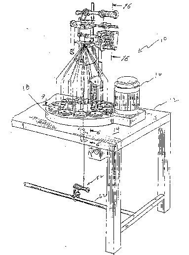
Referring initially to Fig. 1, t:here is
illustrated an apparatus 10 for braiding sutures constructed
according to the present invention. The apparatus 10 is
supported on frame 12 which includes horizontal support
plate 14 as shown. Electrically powered motor 16 is
arranged to drive the apparatus as will be described.
Referring now to Figs. 8 and 9 in conjunction with
Fig. 1, the apparatus includes main caxrier support plate 18
; which defines a pair of tortuous endless tntersecting guide
channels 20 and 22 which extend therearound as shown. Each
channel has a set of yarn carriers guided therein with those
of the yarn carriers in channel 20 designated carriers 24A,
24B, 24C, 24D, 2.~E and 24F, an(} those csrriers in ~hannol 2Z
~`
.
-14-
2~8~-~6f~
1 designated carriers 26A, 26B, 26C, 26D, 26E. Each series of
carriers is arranged to move in opposite direckions while
yarn is selectively dispensed from the selectively intermit-
tently rotating bobbins associated therewith to ~orm the
braided suture. The path of the carriers through guide
channel 20 is illustrated by the arrows A and the path of
the carriers through guide channel 22 is illustrated by
dotted arrows B.
The mechanism for effecting this movement of the
carriers is illustrated in Fig. 8. The carriers 28 each
include an individual carrier support plate 30 to which is
connected a pair of connector shoes 32, 34 which are
positionable within, and traverse the respective guide
channel 20, 22 in a manner to be described. A series of
carrier support and transfer plates 36 and an alternate
series of carrier support and transfer plates 38 ~see Fig.
9) are mounted on main support plate 18 through apertures 40
and are rotated via gear 42 meshing with internal meshing
gear teeth 44 of gear 46 which in turn is driven by a system
of qears associated with the adjacent carriers. Lastly, the
system of gears is driven by motor 16 (see Fig. 1). The
gear train is driven through known gear systems to produce
rotation of the carrier support and transfer plates as
shown, i.e. plates 36 rotating in the counterclockwise
direction and plates 38 rotating in the clockwise direction.
The carrier support and transfer plates 36, 38 rotate at
about 50 to about 500 rpm, preferably 350 rpm.
As the carrier support and transfer plates 36, 38
rotate, each carrier of set 24 is respectively transferred
from one support and transfer plate to an "empty" position
on the next adjacent support and transfer plate so that each
, . . , ~
: ' ' '~ ' '' : :
-15- 2 ~ 6 ~
1 yarn carrier follows a substantially sinusoidal path around
main support plate 18. One series of carriers 24 traverses
an undulating path from left to right and the other series
of carriers 26 traverses an undulating path from ri~ht to
left intersecting with the ~irst path and 180 out o phase
therewith as shown in Figs. 8 and 9.
Referring to Fig. 9, an exemplary portion of each
set of yarn carriers is shown schematical:Ly by circles 24,
26 representing the carrier support plates. The first
series of yarn carriers are designated ~rom left to right -
24A, 24B, 24C, 24D, 24E, and 24F. This series of carriers
traverses the undulating path 20 shown by the solid arrows
"A" as the carrier support plates 36, 38 rotate. The
exemplary carriers of the second series are designated from
right to left, 26A, 26B, 26C, 26D, 26E. These carriers
traverse an undulating path 22 from right to left as shown
by the dotted ~rows "B" as the carrier support plates 36,
38 rotate as shown. Thus as the carrier support and
transfer plates 36, 38 rotate in opposite directions the
"empty" position for each support plate alternates from the
6 o'clock position to the 12 o'clock posit:ion and vice
versa.
Each carrier is respectively transferred from one
carrier support and transfer plate 36, 38 to the next
adjacent carrier support and transfer plate while rotating
about its own center 90 for each quadrant of rotation.
Thus, for example, carrier 26E is positioned at the 12
o'clock position of carrier support plate 36 as shown in
Fig. 9. Carrier tie down bolt~ 25 lie within a line
perpendicular to the radius of the main carrier support
plate 18~ When individual carrier support plate 30 rotates
- -16-
2 ~ 4
1 counterclockwise 9o as shown by the dotted arrow, carrier
26E moves to the 9 o'clock position of carrier support and
transfer plate 3~ and the bolts 25 are directly now in line
with the radius of the main carrisr support plate 18.
Similarly, carrier 24~ will have moved to the 12 o'clock
position of carrier support plate 38 and the tie bolts 27
will have moved from the orientation shown in Fig. 9 (i.e.
in line with a radius of the main carrier support plate 18)
to a position perpendicular to the xadius. With such
movement each carri~r 26 moves one quarter circle to the
left and each carrier 24 moves one quarter circle to the
right. Each quarter circle of rotation is represented by a
90 movement on a sinusoidal path.
As noted, both undulating paths intersect each
1~ other and are identical to guide channels 20, 22. As these
movements progress, yarn is continuously fed off bobbins 48
which are rotatable on carrier shaft 50. As the undulating
movements of carrier support plates 36l 3~ progress, the
connector shoes 32, 34 of the carriers traverse the
respective intersecting guide channels 20, 22. This complex
movement results in the formation of an elongated braided
product as the rotation continuously takes place and the
braid is formed and drawn upward by the take-up roller
system to be described.
Referring now to Figs. 2 and 3, a unique feature
of the present invention is illustrated. The particular
type of braided suture contemplated in the present
application contains a core yarn surrounded by a system of
about 4 to 36 fine denier yarns systematically braided about
the core to ~orm a thin sheath. In the preferred suture
construction the core posses~es a veight which ic
-17-
2 ~ 6 4
1 significantly greater than that of a core o~ a known suture
of equivalent overall denier. Typically, the smallest size
braided suture which includes a core would be size 6/0.
Such a suture has an overall denier of from about 125 to
about 200, and preferably contains a core of about 20-80
denier. Relatively large sutures, i.e. size l and 2 sutures
hav.ing an o~erall denier of from about 2,000 to 4,000
preferably include a core having a denier in the range of
about 800 to 2400. In order to produce a braided yarn
suitable for suture applications, the core tension is
preferably controlled within a predetermined range to match
the tension o~ the braided outer sheath yarns. Fi~s. 2 and
3 illustrate the core tensioning system of the present
invention which maintains the tension within this
lS predetermined range. Tension ranges may vary in dependence
upon the size of the core yarn.
Referring now to Fig. 2, the core tensioning
system 52 is shown and includes supply bobbin 54 containing
core yarn 1. Core tensioning must be precisely controlled
within a predetermined range to match the tension on the
sheath yarns in order to produce a braided product o
desired construction, feel and hand.
Bobbin 54 is mounted for free rotation on shaft 56
and retained by cotter pin 58. A vertical support plate 60
is mounted to cross member 62 of the ~rame 12 by U-shaped
clamp 64 secured by nuts 66 to plate 61. The portion of the
plate 60 above cross member 62 fixedly supports bobhin shaft
56 as shown.
As can be seen more clearly in Fig. 3, pulley
wheel 68 is connected by pin 55 to bobbin 54 for rotation
therewith and defines a central groove 70 about which rope
,. ..
-18-
2 ~
1 72 is positioned. Rope 72 is connected at one end ~y "J"
shaped hook 74 to fixed pin 76. At the other end of rope 72
is weight carrier 78 positioned for supporting weights 73 of
predetermined value. As can be seen, the weight carrier 78
is configured as a central sha~t 80 having a weight carrier
78 at the lower end for supporting annular shaped wPights 73
shaped as shown similar to a split washer. Thus, as the
spool 54 rotates about shaft 56 to feed c3re yarn to the
braiding system the friction drag on the ~pulley wheel 68
restrains the free rotation of the spool !54 in the downward
direction, which is opposite the upward force of the
braiding system and ~raid take-up system. ~hus, by adding
weights to carri~r 78 tension on core yarn 1 may be
increased and by removing weights, tension may be decreased.
Appropriate core yarn tensions for the preferred braided
suture constructions are set out below:
Suture 5izeCore ~enier Tension On Core ~qrams)
2 800-2400 80-90
1 800-2400 70-80
0 400-1200 50-55
2~0 250-700 25-30
3/0 150-300 25-30
4/0 80-150 20-25
5/0 30-100 20-25
Referring now to Figs. 4-7, there is illustrated
another aspect of the system for controlling core yarn which
forms a part of the present invention. In Fig~ 4, there is
shown a tension control system 86 which incorporates a core
tension detector 88 of sufficient sensitivity to detect
tension changes in the core yarn 1 and to discontinue the
braiding operation in the event the core yarn ~ails. In
~'. ' . :
' '' '. . ; ., ' ' ',, ,./
: ~: " . ' "' ' ' . ', ' , .;... . '
,' ' ''' '~,',, ' '
, ' ,' ' ' "~
--19--
2 ~ 4
1 particular, prior art braiding apparatus utilized tension
detectors of substantially less sensitivity for braiding
relatively bulky braids. However, the process of braiding
the preferred sutures rPquires utilization of core yarns
having a denier as low as about 20. Therefore, the tension
~ailure value is correspondingly lower than for prior art
br;ids. Accordingly, the present invention incorporates
tension detector 88 of sufficient sensitivity to detect core
tensions i.e. between about 25 and ~0 grams, without placing
undue stress on the delicate core yarn which would abrade or
break the core yarn. When the core tension exceeds a preset
value (i.e., 80 grams), the core yarn will normally fail
under tension and cause switch 90 to deactivate electrical
power to the apparatus. This permits the operator to
investigate the source of the excessive tension and take the
requisite steps to correct the problem.
Referring once again to Figs. 4-6, after he core
yarn 1 leaves the tension detector it enters core tuba 92
which extends from top plate 16 to approximately 2/3 the
vertical di~tance to the braiding zone. The core tube
contains a unique system of ceramic eyelets 94, 98 which are
resistant to wear caused by any interaction with the core
yarn passing through the tube. Further, the ceramic eyelets
94, 98 present a smooth ceramic surface for the core yarn in
instances when the core yarn engages either end of the tube.
Thus, the integrity of the fine denier core yarn is
maintained in the rare instances where the core yarn shifts
i laterally and engages one or both ends o~ the core tube 92.
This feature is peculiarly significant to applications o~
braiding technology to suture production, whereas prior art
braiding operations which utilized bulkier components such
:
- . i : : : :,, .: . :: ,.: : : .: .: .. :.. , . :, . :
--20--
2 Q ~
1 as cord, ropes, etc., did not require such abrasion proof
features. A third ceramic eyelet 95 is provided on bracket
97 which supports the core tension detection system 86.
Referring now to Figs. 10-15, the yarn carrier
system and yarn tensioning system is illustrated. Referring
initially to Fig. 10, there is shown a cross-sectional view
taken along lines 10-10 of Fig. 9 illustrating the base of a
carrier 28 at the point of transfer between adjacent support
plates 36, 38. Carrier 28 contains carrier support plate 29
which includes downwardly extending connector shoes 32, 34,
which extend into guide channels 20, 22 as described
previously. The feet 30, 32 traverse the respective guide
channel as the yarn carrier is transferred between the
respective carrier support plates 36, 38. In order to
increase the speed of operation of the braiding apparatus
and reduce wear and tear on the apparatus, plastic inserts
100 are provided. Plastic inserts 100 may be made of nylon
or other suitable plastic material, and reduce the friction
between the carrier and carrier support and transfer plate
as the carrier is transferred from each carrier support and
transfer plate to the next. Plastic inserts 100 facilitate
repeated rapid transfer of shafts 102, 103 of the carriers
from one carrier support plate to the next without metal on
metal abrasion. The plastic inserts increase operating
speed and reliability of the apparatus and decrease wear and
tear, thereby lengthening the useful life of the apparatus.
As an added benefit, plastic inserts 100 reduce the noise
level generated by operation Gf the instrument.
Referring now to Figs. 11-12 a typical carrier is
illustrated in further detail. Sheath yarns 3 preferably of
between 0.2 and 6.0 denier are dispensed from bobbin 48
:' ',' ' ~ ' ', ' ~ ,' : ' ' ' . ,' ,:
-21-
20~18~6~
1 where they are directed to ceramic eyelet 103 and then to
compensator eyelet 104 connected via rod 105 to compensator
arm 106 which automatically compensates to adjust the yarn
tension in accordance with braiding needs. The carrier 26
includes compensator arm 106 which pivots about pivot pin
108 as shown. End portion 110 is connected to ceramic
eyelet yarn guide 104 while the opposite end portion 112 of
pivot arm 106 engages pin 114 which is biased upwardly by
light coil spring 116. Pin 114 is connected to pawl 118
arranged to float into and out of engagement with radial
slots 120 on the lower surface of yarn bobbin 48 shown in
Fig. 12. This structure results in the pivotal bias of
compensator arm 106 about pin 108~ Pin 122 moves upwardly
and downwardly in vertical slot 124 in carrier housing 126
while tra~ersing the moving arcuate slot 126 in compensator
arm 106.
In operation, yarn is drawn upwardly by the
braiding system, and when the tension of the yarn exceeds a
predetermined value the end portion 112 of pivot arm 106
depresses pin 114 against spring 116 causing pawl 118 to
withdraw from a slot 120 in the bobbin 122. This permits
outfeed of sheath yarn 3 until the tension in the yarn is
reduced to a second predetermined value whereby the end
portion 112 of pivot arm ~06 pivots upwardly under bias o~
spring 116, permitting pawl 118 to re-enter a radial slot
120 in bobbin 122 thus preventing further outfeed of the
sheath yarn 3 until the tension of the braiding take-up
increases sufficiently to recycle the compensator arm 106.
Thus, the tension of the sheath yarns is controlled within a
precise range, particularly by selecting a spriny 116 which
is within a predetermined range o~ spring rates. Prior art
. ~ 1 ,, ..'.', . . .
, ' . ' ~ .: ' . . ' ' " ' ' ' ~.; '.' .' '. ' ' ".
-22- 2 ~ 6 ~
1 braider utilized a spring 116 of significantly greater
spring rate than is contemplated herein due to the fact that
braiding was accomplished with heavier braiding materials.
In addition, in prior art braiders pin 122 was also arranged
to be biased downwardly by a spring positioned centrally of
shaft 50. In the present apparatus the cantral spring has
been eliminated and spring 116 has been selected to have a
reduced spring rate in the range of from about 0.6 to 0.7
pounds per inch, the standard spring on such braiders having
a much higher spring rate on the order of about 0.9 to about
1.0 pounds per inch. Reducing the spring rate reduces the
tension force on the yarn necessary to cause pivot arm 106
to rotate and withdraw pawl 118 from slot 120, thereby
permitting the bobbin to rotate and pay out additional yarn.
The reduced spring rate accommodates the relatively lower
tensile strength associated with sheath yarns of
aforementioned preferred denier range suitable for producing
braided sutures. The production of such sutures is thus
carefully and precisely controlled to accommodate the fine
character, not only of the finished braided suture, but
particularly of the yarn components thereof.
~ eferring now to Figs. 13-15, the unique yarn
dispensing system according to the present invention is
disclosed. Bobbin 48 is integrally constructed of a
lightweight material such as molded nylon or other plastic
material. The bobbin is constructed to have an overall
weiqht of about 20 grams and a minimum diameter dimensionad
so as to reduce inertial forces on the delicate sheath
yarns. In order to reduce tension on the yarns further, the
number of radial segments 124 which control the release
; 35
, . . ,,:,:
- . . . .. .... . ... ... .
,'. ".' '.',, ,. ',; . ~. ,. . ~
:: , . '' ; : ; . . .:- , '
-23--
2 ~ 4l 6 ~
1 point of the bobbin have been reduced to nine segments as
shown r
This compares to prior art bobbin and carrier
assemblies wherein a metal bobbin is mounted over a shaft.
The bobbin engages and is ~ixed by screw mounting so as not
to rotate relative to the top surface of a metal plate on
the carrier. The bottom surface o~ the metal plate has 12
or more segments to engage the carrier pawl. The prior art
bobbins ara also of smaller diameter than the bobbins of the
present invention, and yet weighed about 50 grams. The
combined bobbin and adaptor of prior art braiders have a
total weight of about 85 grams. The increased diameter and
light weight of the present bobbin, together with the
integral pawl engaging segments and reduced number thereof,
further reduce the force which must be exerted on the yarn
in order to unwind the yarn from the bobbin.
In particular, the unique braider bobbin of the
present invention is specifically constructed to adapt the
apparatus for braiding fine denier yarns applicable to ~ine
sutures and is preferably constructed having the following
characteristics:
a) rPduced mass integrally molded nylon
construction of approximately 20 grams, as
compared to prior art bobbins of
approximately 50 grams, and prior art bobbin
and adaptor assembly weighing about 85 grams;
b) reduced number of pawl engaging segments 124
which are integrally molded with the bobbin,
preferably 9 segments, not more than 11,
versus prior separate adaptor structures
having 12 or more pawl engaging segments and
. .
24--
- 2~ 8~
1 higher mass. This structure produces greater
circumferential spacing between segments,
permitting improved engagement by pawl 118 at
high rotational speeds;
c) bobbin diameter approximately 20mm as
compared to lesser diameter prior art
bobbins. This feature reduces the tension
force on the yarn required to turn th~ bobbin
and stabilizes the bobbin and yarn movements;
and
d) unitary construction bobbin, injection molded
nylon (or other moldable plastic) permitting
relatively large diameter bobbin at reduccd
weight with close tolerances (i.e. + .~5 mm)
for precision in winding from flange to
flange.
Referring now to Figs. 14 and 15, the unique quick
connect~quick release bobbin holder is illustrated. As
noted previously, bobbin 48 is constructed of a lightweight
moldable material such as nylon and definles a central
opening extending the length of the bobbin. The bobbin is
positioned about upstanding carrier shaft 50 and secured by
top holder 128 as shown. Top holder 128 is comprised of a
folded wire clip slidably positioned within collar 132 which
is fixedly attached to the top o~ shaft 50 by known means
such as inter~erence fit, threads, adhesives etc. The
folded wire clip is biased downwardly by coil spring 13~
which is arranged to be compressed by engagement with disc
136 attached to the lower end of clip 128 when the clip is
raised upwardly. Clip 128 is looped at the top at 138 to
~oxm an arm 140 which is dimensioned to engage the uppQr end
i'
;~
.;i~
--2!~--
2~ ~3~
I surface o~ the bobbin ~8 to maintain the position of the
bobbin on the shaft 50 without interference with the
rotation of thP bobbin. The clip is preferably constructed
of a resilient spring wire which resiliently retains the
bent shape imparted to it. Further, it can be seen that arm
142 is pre~erably dimensioned to extend downwardly
su~ficient to retain the bobbin in position while being
dimensioned to provide a slight space 144 b~tween the lowar
~nd portion of arm 142 and the top surface of the bobbin.
Quick positioning and removal of the bobbin is
accomplished as follows. ~lip 128 is pulled upwardly
manually against the bias of spring 134 until the lower end
portion of arm 142 folds inwardly under the spring ~ias of
loop 138 and rests atop collar 132. This position permits
insertion and/or removal of bobbin 48 onto or from shaft 50.
After removing the old bobbin or adding a new bobbin with
new yarn supply, clip 128 is manually twisted to cause
lateral movement of arm 142 so as to be repositioned atop
the bobbin 48 thereby retaining the bobbin in position for
operation. Thus, a bobbin may be replaced readily by manual
manipulation of the clip 128 as described. In this regard,
prior art braiders utilized relatively complex devices to
secure bobbins to feed braid components for rope or other
braids.
Referring now to Figs~ 16-19, the take-up system
for the braided suture product is illustrated. Fig~ 16
illustrates the final formation of the braided suture and
the take-up roller system leading to final winding of the
finished product on take-up spool 146. In particular, core
yarn 1 and sheath yarns 3 are formed into a final braided
suture 5 which is first directed to take-up "tensioning"
. . ,, :
-26-
2 ~
1 rollers 142, 144 and thereafter to final take-up spool 146
where the product is systematically wound in uniform layers
about the spool. The braided product 5 is wound
continuously about rollers 142, 144 to stabilize the product
prior to winding about take-up spool 146. Ceramic eyelets
179, 190 and 188 guide the suture from the. braiding zone to
the take-up rollers and then to the take-up spool without
abrasion or other damage.
Take-up clutch 148 is shown in Fig~ 17 to
precisely control the tension on the finished product via
final spool 146. Clutch 148 is mounted on spool shaft 150
and includes internal clutch shaft 152 having first clutch
plate 154 at one end sacured to shaft 150 by set screw 156
for rotation with the shaft. Molded nylon pulley wheel 158
is slidably positioned over clutch shaft 152 for slidable
rotation relative to clutch plate 154. Second clutch plate l;
160 is connected by screw 162 for rotation with clutch shaft
152. Screw 162 .is fitted loosely in a slot (not shown) for
movement in the longitudinal direction of shaft 152 to
permit clutch plate 160 to move toward and. away from pulley
wheel 158 by pressure of coil spring 166 when spring 166 is
compressed by turning knurled wheel 168 which is fitted by .l
threads 170 about the end of shaft 152 as shown. Thus, by
threadedly rotating wheel 168 clockwise to advance the wheel
toward the spring 166 the force transmitted by the spring on
tha clutch plate 160 is increased, thereby increasing the
friction forces between pulley wheel 158 and clutch plates
160 and 154. By turning wheel 168 counterclockwise, the
wheel moves outwardly of shaft 152 and the. spring force is
reduced thereby reducing the ~ric~tion forces and permitting
free rotation of pulley wheel 158.
.-., i : , . ~ .,:,
, , ., ~ : : .
-~7-
2 ~
1 Referring further to Fig. 17, pulley wheel 172 is
connected to shaft 174 which is driven by chain 176 shown
schematically in the Fig. Chain 176 is powered by power
driven sprocket 178 and thereby produces rotation of shaft
174 via large sprocket 180 at a reduced rate of rotation in
accordance with the selected ratio o~ the size of sprocket
178 to the size of sprocket 180. Pulley wheel 172 is in
turn connected to endless drive belt 182 which is fabricated
of a suitable, flexible elastomer material and has a
lQ circular cross-section and elongated construction.
Referring once again to Fig. 17, shaft 174
contains diamond shaped guide grooves 184 for reception o~
similarly shaped members ~ormed integrally with product
guide member 185 such that continuous rotation of shaft 184
will produce alternating repeating movement of the guide
member 185 arranged to move in the direction o~ arrows "C"
and "D" as the shaft 184 rotates. Plate 186 attached to
guide member 185 contains ceramic suture guide 1a8 which
guides the finished braided suture received from take-up
rollers 142, 144 through ceramic guide 190 affixed to
support arm 192 to take-up spool 146.
In operation, as shaft 174 rotates, guide member
185 traverses the right hand portion o~ the shaft. The
guide member 185 alternates from the direction of arrow C to
the direction of arrow D in a repeating manner to guide
finished braided suture product onto spool 146 in successive
uniform and even layers. The tension on the braided suture
may be selectively increased or decreased as desired, by
turning clutch adjustment knob 168 as described previou~ly. ;
The capability to adjust the tension on the finished product
as lt is being wound onto spool 146 is significant. As the
;,
, '" , ' .
', : , ~ .:., ,' . . . :, !
-2B-
2~8 r~
1 diameter of the final package increases, the ratio of the
linear speeds between the take up spool 146 and the grooved
rollers 142, 144 increases thereby increasing the tension on
the finished product. Adjustment of the tension on the
finished product is then possible by adjusting clutch 148 to
maintain appropriate tension on the suture with a high
degree of accuracy and control~
Re~erring once again to Fig. 17 in conjunction
with Fig. 18., the braid ~ake-up roller system is
illustrated. As can be seen in Fig. 18, the take-up rollers
l42, 144 are configured to include relatively sharp "V-
shaped~ grooves for braided suture take-up to facilitatP
appropriate contact with braided suture products of a wide
range of sizes, including extremely small suture diameters.
Further, since the braid is continuously wrapped around the
rollers 142, l44, it has been found that it is possible to
increase the number of gr~oves, i.eO wraps, for a given
length of rollers, thereby increasing the friction conta~t
between braided suture product and the rollers. This
facilitates increased control over the ~inished braided
suture product and minimizes slippage between the suture and
the rollers. Preferably, the suture is wound around taXe-up
rollers 142, 144 in a figure 8 configuration, as shown in
phantom in Fig. ~6~
As can be seen in comparing the rollers shown in
Figs~ l8 and l9 with the prior art rollers (see Figs. 21 and
22), it will be readily appreciated that the contact between
the product and the rollers is increased with the rollers
constructed according to the present invention as shown in
Figs. 18 and l9. In addition, it is noted that the take-up
rollers constructed according to the inven1:ion are o~
~5
; .. . .
` ' ~, ' : . ` .. :,. ..
' , ' ,
-29-
2~8~6~
1 machined plastic material, such as nylon, as opposed to the
molded prior art rollers shown in Figs. 21 and 22. The
prior art rollers were of molded construction and included
mold part lines 194, an imperfection which does not
adversely a~fect braided products of heavy duty
construction, i.e. rope construction: howe~er, the braiding
of fine denier sutures as contemplated herein requires take-
up rollers of improved construction having smooth surfaces
which not only avoid adverse affects on th~e sutura product,
but which also produce sufficiently controlled friction to
permit take-up of the product without damage. The smooth
surfaces of the machined plastic rollers 142, 144 as shown
in Figs. 17 and 18 achieve these objectives.
Referrinq to Fig. 18, the take-up rollers of the
present invention are machined to include grooves having
inclined side walls terminating in a ~lat bottom surface.
The overall depth "d" of the groov should be dimensioned to
accommodate a range of suture sizes. A depth range of about
0.1 to 0.2 inches may be appropriate, and a depth of about
0.16 inches is preferred. The width of the flat bottom of
the groove, shown as dimension "w" in Fig. 18, is preferably
about .002 inch. The inclined surfaces define an angle 0
with the outer surface of the take-up roller. It has been
found that appropriate angles are within the range 55 to
65, and preferably 60 to 61.
Figs. 19 and 20 illustrate the quick connect/quick
xelease feature utilized to retain the take-up spool 146 on
shaft 150 shown in Fig. 17. Shaft 150 is dimensioned to
receive pin 196 and includes a groove 198" A generally
endless looped locX member having a CUt~OIlt portion 202
shaped to receive pin 196 is positioned within the slot and
,. ~... .
., j . :
~30- 2~8~4
1 is rotatable from a position transverse o~ the shaft 150 as
shown in Fig. 19, to a position in alignment with shaft 150
as shown in Fig. 20. The position of lock member 200 shown
in Fig. 19 retains the spool 146 on shaft 150 and is secured
in position by appropriately dimensioning space 198 relative
to pin 196. The position of lock member 200 ~hown in Fig.
20 permits ready removal of the take up spool 146 ~or
replacement ~ith an empty spool. Thus, the quick release
feature of lock member 200 facilitates ready replacement o~
a full spool 146. As shown in Fiy. 17, member 146c is fixed
to shaft 150 by pin 146d. Pin in ~lot engagement of pin
146a in slot 146b restrains spool ~46 mounted on shaft 150
against rotation relative to shaft 150.
Ref~rring to Fig. 23, an alternate construction of
a tensioning take-up clutch is illustrated a~ 204. rlutch
204 is operative similar to the clutch 148 described
previously, but includes split pulley 206 h~ing outer
annular portion 208 and inner portion 210 separated by ball
bearings 212. Thus, the construction shown permits precise
control over the tension exerted on split member 210 by
frictional engagement with memhers 154, 160 independently of
friction between split member 210 and clutch shaft 152. The
foregoing alternative structure facilitates improved
a~curacy in the control of the tension exerted on the final
braided suture. Fig. 24 illustrates an alternate
arrangement for tensioning and take-up rollers 142, 144. In
the arrangement shown, rollers 214, 216 are positioned
longitudinally and driven by common belt drive 218.
Finished braided suture product 5 is shown.
It will be readily appreciated that the features
of the present invention as described hereinabove make it
:;,,
--31--
2 ~
1 possible to produce a fine denier braid capable o~
application as a suture.for surgery. More particularly, the
braiding apparatus is well suited ~or high speed production
of consistently high quality final braided suture products
having an overall suture denier ranging from as low as about
50 denier to as large as about 4,000 denier. Core yarns
will have a preferred denier of from as low as about 20
denier to as high as about 2,400 denier, and sheath yarns
will have a denier of from as low as about 0.2 denier to as
high as about 6.0 denier.
~5
~-
.. . .
. . .: ~ .: ~ , . . ~ :
- . . .
.