Note: Descriptions are shown in the official language in which they were submitted.
2 ~
ADAPTABLE HUNTING STAND FOR LADDER-LIKE USE OR A-FRAME USE
This invention relates to a sectional hunting stand,
adapted for ladder-like use or for A-frame use when mounted on an
all terrain vehicle.
Elevated observation stands, providing a hurlter secure
seating and a wide visual range, are desirable when hunting deer
and other game in forested areas, fields, and reforesting areas.
The relatively easy access to these areas now provided by all ter-
rain vehicles (ATV=) has encouraged the development of such stands
to be used while mounted on ATVs.
Such de-mountable stands known to the inventor are of
two major types. One such type, described in U.S. Patent No.
4,800,986 to Hayes, and U.S. Patent No. 4,787,477 to Dolan, re-
quires front and rear leg members which create a modified "A"
frame to support a seating platform between the leg members. ~ ;
A second type, disclosed in U.S. Patent No. 4,614,252 to
Tarner, and U.S. Patent No. 4,625,831 to Rodgers shows, mounted on
an ATV, a single ladder element whose attached seat platform abuts
a tree for fixed support.
The seating platforms of such stands have heretofore ;
been fixed and unadjustable as to their angularity. The patent to -
; Hayes appears capable of limited adjustment at what appears to be
some sacriflce of stability. ;~
The purposes of the present invention are to provide a -~
hunting stand which: allows the angle of its seat platform to be
adjusted to level the seat relative to the slope of the terrain; ~ t
provides, by differing simple assembly of its elements, a high or
low "A"-frame type stand, and a variable height single ladder
stand which may be either ATV mounted or ground-standing and
leaned against a tree; and which mounts and dismounts easily from
rods affixed fore and aft on an ATV. Such purposes are achieved
by use of the interactive parts (seat platform, ladder elements,
and base connectors) of the present invention, each hereinafter
described.
The seat platform of the present invention is comprised
of elongated parallel members, spaced apart and running from front
to back. The length of the parallel members at the seat platform
back is symmetrically graduated from longer outer members to
shorter inner members, forming an inwardly curved seat back
adapted to fit against a tree.
Two pairs of downwardly projecting pivotable sockets, ~ ;
one pair provided at the seat front and one pair at the seat back,
may be adjusted and fixed at a chosen angle relative to the seat
platform. The seat sockets are so sized as to fit over the upper
side rails of the ladder elements of the present invention.
Each ladder element of the present invention has three
rungs attached to ladder sidepieces which extend higher than the
highest rung and lower than the lowest rung. The ladder elements
are so constructed that they are fittable onto each other, so that
in combination they may form A-frame and single-ladder stands of
varying heights.
Chosen ladder elements are equipped at their bases with
; novel grasping connectors, by which the ladder element may easily
be manually mounted and demounted from bars affixed to an ATV.
. j , ,
The connectors attach so as to allow the ladder element to pivot
on these bars to accommodate varlous angles of the ladder sections
resulting from insertion into the fixed-angle seat sockets.
FIG. 1 is an isometric view of the underside of a level-
ing seat platform constructed from elongated paralleI members
whose sockets at the seat front are interconnected so as to be
angularly adjustable by turnbuckle means, and whose sockets at the
seat back are shown folded between the elongated parallel members.
FIG. 2 is a fragmentary view of a seat platform somewhat
modified from FIG. 1, showing sector plates fitted with pins to
æo~so~
adjust the angles of the sockets relative to the seat platform.
FIG. 3 is a view of a typical ladder element with its
- lower sidepiece ends inserted in simple sleeves, the left sleeve
being shown partially broken away.
FIG. 4 is a partially broken-away side view of a base
connector sleeve whose downwardly-e~tending uncompressed bent
,.. ...
spring extends outward from, but is retained within the sleeve by
a re~tention bolt, and whose grasping ends are positioned outward ~ i~
of a graspable rod on an ATV, shown in phantom lines.
FIG. 5 is a broken front view of the base connector
~`~ sleeve of FIG. 4, whose sleeve is being driven downward so that --
the diagonal edge~of its camming blade contacts the outer side of
the bend of the bent sprlng, driving the blade outward.
` ~ FIG. 6 is a broken front view, similar to FIG. 5, show- ;-
ing the bent spring of the connector sleeve in its final grasping
position with the sleeve driven fully downward about it so that -~;~
the inner side of the bend of the bent spring is engaged by the ~ ~ ~
top edge of the blade. ;~ `i
FIG. 7 is a side view of the base connector sleeve in
~20 position corresponding to FIG. 6. `
~` ~ ; FIG. 8 is a side view of such a leveLing seat platform
` ~ mounted for low A-frame use atop opposite ladder elements attached -~ ;-
by base connector sleeves onto an ATV, the angle of the seat plat-
form hav1ng been adjusted to~compensate for downward slanting ter-
raln, and a ladder element used as a stabilizer.
~ FIG. 9 iS a view, principally from the front, of a
-~ ground support fitted wlthin~the sleeves of a ladder element.
The present invention provides component parts which may
~; be used to assemble an ATV-mounted A-frame hunting stand of dif- -~
ferent chosen heights whose seat~platform may~be leveled to com-
pensate for hilly terrain on which the ATV may be parked; these
component parts may also be used to assemble a single-ladder hunt-
. ~
- 3 - ~ ~ ~
1 ~
/ ~
3~.
ing stand of different chosen heights which may be either ATV-
mounted or ground-standing. The component parts of the present
invention are: a leveling seat platform, ladder elements, and eas-
ily mountable grasping base connector assemblies.
The seat platform 16 of the present invention, whose un~
derside is shown in the isometric view of FIG. 1, is constructed
of two outer elongated members 20, 20', two intermediate elongated
members 22, 22' of length identical to the outer members 20, 20',
and two shorter inner members 24, 24', all made from square metal
tubing, and running spacedly parallel to each other from a seat
platform front, generally designated 26, where their ends are -
evenly aligned, to a seat platform back, generally designated 28,
where the two shorter inner members 24, 24' terminate inwardly of
the intermediate ~embers 22, 22' and outer members 20, 20', creat-
ing an inset adapted to fit against a tree trunk.
The inner elongated members 24, 24' and the intermediate
elongated members 22, 22' are held uniformly apart by spacers 38
at both the seat front 26 and at the seat back 28; the intermedi-
ate elongated members 22, 22' and the outer elongated members 20,
20' are held similarly apart both at the seat front 26 and seat
: back 28 by hollow pivotable sockets 40, 40'. The elongated mem-
bers 20, 20', 22, 22', 24, 24' are cross-drilled and connected,
`' spacedly inward of the seat front 26, by a front cross-rod 34,
and, spacedly inward of the seat back 28, by a back cross-rod 36,
each rod 34, 36 extending through the separating spacers 38, 38'
and sockets 40, 40' and secured by a nut 37, 37' at the outermost
walls of the outer elongated members 20, 20'.
The pivotable hollow sockets 40, 40' at the seat front :
26 are connected, as shown in FIG. 1, by a bar 44 extending be-
tween and welded to the front outer faces 42, 42' of the sockets
40, 40'. A screw adjustment turnbuckle 50 is connected to the bar
44 by an eye 49 and extends under the seat platform 16 to a
'' 20!~ 3'~ ,
bracket 52 mounted between the inner elongated members 24, 24',
and located between the seat front 26 and back 28. Adjustment of ~ .
the turnbuckle 50 fixes the angle of the sockets 40, 40' relative
to the seat platform 16 thereby allowing it to be leveled relative
to the terrain. Optionally, a second turnbuckle may extend from a
similar bracket to a similar connecting bar welded to the outer . ~;
faces 42, 42' of the pair of sockets 40, 40' at the seat platform
back 28.
An alternate construction for leveling the seat platform
~ ~ .
16 is~shown in fragmentary view in FIG. 2. Between outer elon~
gated members 20, 20', and the intermediate elongated members 22,
~ 22'~on either side of each of the hollow sockets 40, 40', are
.. ~ mounted a pair of 90 sector plates 53, 53', the distance between
s~.
the members 20, 20', 22, 22', so being increased as to accommodate
the width of the plates. At their 90 intersections, the plates
53, 53' are mounted on the front cross-rod 34, and the curved --.
outer edge of each of the plates 53, 53' is mounted on cross-bolts ~:
; ~ 56, S6' extending between the outer elongated members~20, 20' and ... '.
the lnner elongated members 22,:22' immediately inward of the seat
:20~ platform~front 26. Inwardly of the curved edge of each plate 53,
53'~ i9 a plura~lity of cross bores 58,~58' in identical arcuate ;
~: patterns through which detent pins 59, 59', may be inserted on at -:~
;:~ least the outer sides of~each socket 40 to limit its rotational
movement~and thereby~fix the~angle~of~the sockets 40, 40:' relative
to the seat~platform 16~
; All sockets 40, 40' are hollow and have identlcal inte-
; rior:width and depth and are so sized that they may:receiye the :~
upper ends of the sldepieces 66, 66'~of the ladder element 60
hereinafter described. :~
Each ladder element 60, as illustrated in FIG. 3, is :~
constructed of square:metal tublng:;and has at least three rungs, ;~
: an uppermost rung 68, an intermediate rung 70, and a lowermost
~ 5 ~ j . ; :
'~ ,' ' ;'
rung 72 extending between parallel sidepieces 62, 62' of constant
cross-section. The sidepieces 62, 62' extend higher than the up-
permost rung 68 and lower than the lowermost rung 72. Upper
sidepiece ends 66, 66' of a ladder element 60 may be fitted into
the pair of sockets 40, 40' at the front 26 or back 28 of the seat
platform 16. At the lower end of each sidepiece 64, 64' a hollow
sleeve 80 of constant cross-section having interior width and
depth identical to the width and depth of the seat platform sock-
ets 40, 40' enabling a slidable fit between the sleeve 80 and an
upper sidepiece end 66 is fitted on, and alternately may be welded
onto each ladder lower sidepiece end 64, 64' to extend as shown in
the broken cross-section of FIG. 3, from the lowermost ladder rung
~` 72 to substantially beyond the lower sidepiece ends 64, 64'.
! Upper sidepiece ends 66, 66' of a ladder element 60 may
be fitted into the downward-extending sleeves 80, 80' of an iden-
tical ladder element 60'; two or more of such ladder elements 60,
60' may thereby combine to form ladder sections 76 as hereinafter
described and illustrated in FIG. 9.
The present invention contemplates the use of a plural-
ity of ladder elements 60, all but two being fitted with the hol-
low sleeves 80, just described, these two being fitted with grasp-
ing base connector assemblies 100, hereinafter described.
For ATV-mounted use, the novel grasping base connector
assemblies 100 of the present invention secure a hunting stand
hereinafter described and illustrated in FIG. 8 as 160, assembled
from a seat platform 16 and ladder elements 60, 60', to trans-
verse, graspable front rods 152 and rear rods 154 mounted on an
ATV 150. As illustrated in FIG. 4, each connector assembly 100
includes a hollow, rectangular sleeve-like member 102 fitted with
a bent spring 120, a retention bolt 118 and latching means 129.
The sleeve-like member 102 is of constant cross-section,
and its interior width and interior depth are identical to those ;
- 6 -
`. ','','' ,'~'' '
$ ~ ~ ~
of a connecting sleeve 80 and a seat platform socket 40. Outer -~
walls of the sleeve-like member contain bolt-accommodating holes -~
115, 115', spacedly above the sleeve open lower end, and one outer
wall contains spacedly above a bolt-accommodating hole 115 a ver-
tical slot 116, hereinafter referred to.
The bent spring 120 is formed from metal narrower than
the interior width of the sleeve-like member 102. It has a cen-
tral bend 122 permanently set at an angle of less than 90. From
its bend 122 two opposing arms 124, 124' extend, each arm termi-
nating in an opposing curved grasping portion 126, 126'. At the
juncture between one arm 124' and its grasping portion 126' a stop ;~
128 extends perpendicularly inward toward the opposing arm 124.
The spring is mounted by inserting its central bend 122, `` ~ `
as shown in FIG. 4, into the open lower end of the sleeve-like
member 102 beyond the bolt holes 115, 115'; it is there retained
by insertion of the bolt 118 through the bolt holes 115, 115'. As
long as the spring 120 is uncompressed, its grasping portions 126,
126' are spread more widely than the diameter of the rod hereinaf-
ter described.
In order to secure the bent spring 120 ln a retracted
compressed~position within it, the sleeve-like member 102 is fit-
ted with releasable latching means 129. A preferred latch, illus~
trated in FIG. 5, includes the vertical slot 116 through the
sleeve-like member outer wall 106, a flat spring 130, and a
camming blade 136 which may enter the sleeve-like member 102
through the slot 116 so that its top edge w111 extend horizontally ;~
into the sleeve-like member interior width. The lower end of the
flat spring 130 is secured to the sleeve-like member outer wall
106 by the retention bolt 118.
Th~ ca~ming blade 136, shown cammed outward in FIG. 5,
has a diagonal cam edge 138 whose lead angle may be approximately ;~
;~ 30 from the flat spring 130, and a perpendicular top edge 144.
- 7 - i ,
2~8~
The blade 136 may be formed integrally with the flat spring 130 by
bending it perpendicular to one edge of the flat spring 130; a
projecting release tab 140 may be bent perpendicularly outward
from its other edge. The camming blade 136 may enter the sleeve-
like member 102 through the slot 116 in the sleeve-like member
outer wall, so that its top edge 144 extends horizontally into the
sleeve-like member interior width.
Such grasping connector sleeve assemblies 100 are
slidably fitted on, or welded onto, the lower sidepiece ends 64,
6~' of those ladder elements 60 which are to be mounted on an ATV
equipped with fore-and-aft mounted transverse rods 152, 154 re-
spectively.
Referring to FIGS. 4 through 7, the curved grasping por-
tions 126 of the uncompressed bent spring 120 of a connector 100
are positioned about an ATV-mounted rod 156. As shown in FIG. 5,
downward movement of the sleeve-like member 102 toward the rod 152
compresses the bent spring 120, as the spring central bend 122
travels relatively upward into the sleeve-like member 102 to con-
tact the diagonal edge 138 of the camming blade 136, forcing the
blade 136 outward through the slot 116, to allow the spring cen-
tral bend 122 to pass above the blade top edge 144. As the cen-
tral bend 122 so passes, the flat spring 130 returns the camming
blade 136 to within the sleeve-like member 102, the blade top edge
144 now being beneath the spring central bend 122, as shown in
phantom in FIG. 6, thus to retain the bent spring 120 in com-
pressed position so that its curved grasping portions are secured
about the rod 152, as shown in side view in FIG. 7.
Demounting of the ladder element 60 is accomplished by
manually pulling the release tab 140 outward, thereby moving the
camming blade 136 ou~ward through the slot 116 and releasing the ~ ~-
bent spring 120. The sleeve-like member 102 may then be raised to
permit the bent spring 120 to spread and release the bar 156. ;;~
- 8 -
, . ,., ,`.: ' '~:~'.
~, :
`:
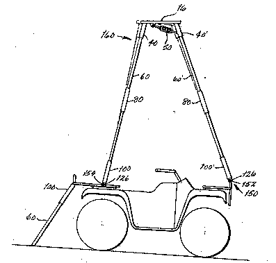
The low A-frame hunting stand 160 illustrated in FIG. 8
shows the leveling seat platform 16 mounted atop oppo~ing ladder
elements 60, 60', the seat platform sockets 40, 40' at the seat
front 26 fitted over the upper sidepiece ends 66, 66' of a ladder -
element 60, and the sockets 40, 40' at the seat back 28 fitted ~-
over the upper sidepiece ends 66, 66' of the opposing ladder ele- ~ ~-
ment 60'. The grasping base connector assemblies 100, 100' af~
fixed to the lower sidepiece ends 64, 64' of the opposing ladder
elements 60, 60' rotatably secure the stand 160 to transverse rods
:-: :, . -
156, 156' installed on the ATV 150. -
The seat platform 16 may be leveled relative to sloping
terrain on which the ATV 150 may be parked; this is done by ad-
justment of the turnbuckle 50 to fix the angle of the seat plat-
form sockets 40, 40' relative to the seat platform 16. FIG. 8 il- ;
lustrates in phantom lines the angularity of the seat platform 16
and ladder elements 60 prior to such adjustment, and in solid
lines, their angularity after adjusting. The curved grasping por- ~ `
tions 126, 126' of the connector assembly may pivot on the rods ; ~ ~`
152, 154 to accommodate the chosen angle of the sockets 40, 41 and
ladder elements 60, 60' inserted therein.
The embodiment illustrated in FIG. 8 shows two ladder
elements 60, 60', on each side of the seat 16. The height of the ~-
., j ,
stand may, as should be obvious, be increased by interpositioning
a third ladder element 60, 60' on each side.
A single ladder hunting stand, not shown, may be assem-
bled by mounting a single ladder element 60 or a ladder section 76
- of two or more ladder elements 60, 60' onto the forward rods 152
of the ATV 150. The seat platform 16 may then be mounted atop
the ladder upper sidepiece ends 66, 66' by the sockets 40, 40', on
the seat front 26 and the inset seat back 28 leaned against a tree
trunk.
To brace the ATV 150 against deflection when such a
:::
`- 2~5~
stand is climbed on, a ladder element 60 fitted with grasping base
connector assemblies 100, 100' may be attached, as shown in FIG.
8, to the rod of an ATV rack assembly which extends beyond the ATV
fender, and so rotated as to contact the ground.
For use independent of an ATV, a ladder element or ele-
ments 60 may be erected on the ground support 140, made of square
metal tubing and illustrated in FIG. 9. It includes two side
rails 141, 141', each having a vertically extending portion 142 of
the same exterior width and ~epth as the interior width and depth
of a connecting sleeve 80, and an outward and downward extending
leg 144. The side rails 141, 141' are connected between their
vertically extending portions 142, 142' by an upper rung or rungs
;~ 148 and between their outward extending legs 144, 144' by a longer
lower rung 150.
To assemble a single ladder ground stand, not shown, a
ladder element 60 or a ladder section 72, having lower sidepiece
ends 64, 64' fitted with connecting sleeves 80, may be mounted
atop the ground support vertically extending members 142, 142', as
shown in broken view in FIG. 9. The seat platform 16 may then be
mounted and leaned against a tree as for the ATV-mounted single
; ladder stand previously described.
.
As various modifications may be made in the construc-
tions herein described and illustrated without departing from the
scope of the invention, it is intended that all matter contained
in the foregoing descriptlon or shown in the accompanying drawings -
shall be taken as illustrative rather than limiting.
~''"',"'-''""' ,-'
~- :
~ ..... , ., -
. ,:, '.,, . ,: :'
', '. ,.'' '~ `. ~.
- 10 - ' ';'`'"'''''~'"'
., " ~,...