Language selection

Search

Patent 2048847 Summary

Third-party information liability

Some of the information on this Web page has been provided by external sources. The Government of Canada is not responsible for the accuracy, reliability or currency of the information supplied by external sources. Users wishing to rely upon this information should consult directly with the source of the information. Content provided by external sources is not subject to official languages, privacy and accessibility requirements.

Claims and Abstract availability

Any discrepancies in the text and image of the Claims and Abstract are due to differing posting times. Text of the Claims and Abstract are posted:

  • At the time the application is open to public inspection;
  • At the time of issue of the patent (grant).
(12) Patent: (11) CA 2048847
(54) English Title: BLOW TUBE REMOVAL
(54) French Title: BLOC-NOTES FORMAT PORTEFEUILLE
Status: Expired and beyond the Period of Reversal
Bibliographic Data
(51) International Patent Classification (IPC):
  • B01D 46/42 (2006.01)
  • B01D 46/04 (2006.01)
  • B01D 46/24 (2006.01)
(72) Inventors :
  • BRAME, WARREN L. (Australia)
(73) Owners :
  • HOSOKAWA MICRON AUSTRALIA PTY. LTD.
(71) Applicants :
  • HOSOKAWA MICRON AUSTRALIA PTY. LTD. (Australia)
(74) Agent: GOWLING WLG (CANADA) LLP
(74) Associate agent:
(45) Issued: 1998-10-06
(22) Filed Date: 1991-08-09
(41) Open to Public Inspection: 1992-02-15
Examination requested: 1993-07-14
Availability of licence: N/A
Dedicated to the Public: N/A
(25) Language of filing: English

Patent Cooperation Treaty (PCT): No

(30) Application Priority Data:
Application No. Country/Territory Date
PK1708 (Australia) 1990-08-14

Abstracts

English Abstract


A dust collector blow tube having a blow tube (22) being open at a first end (32)
and closed at a second end (36), the first end being reasonably and sealingly received over
a supply pipe (12); the second end (36) being acted up by pressure means to place
pressure on the second end (36) to force the first end (32) over the supply pipe (12); the
pressure means is a cylinder (42) mounted about a vertical shaft (44) parallel to but spaced
from the longitudinal axis of the cylinder (42) so as to provide a cam effect, rotation of the
cylinder (42) about the vertical shaft (44) providing the necessary pressure.


French Abstract

La présente invention a pour objet un tuyau d'évacuation forcée (22) pour collecteur de poussière dont une première extrémité est fermée (32) et une deuxième extrémité (36) est ouverte, la première extrémité étant raccordée à un tuyau d'alimentation (12) par l'intermédiaire d'un joint étanche; la deuxième extrémité (36) est soumise à une pression exercée pour enfiler la première extrémité (32) sur le tuyau d'alimentation (12); la pression exercée sur la deuxième extrémité (36) est exercée par un cylindre (42) monté à proximité d'un arbre vertical (44) disposé parallèlement et à faible distance de l'axe longitudinal du cylindre (42), de façon à entraîner, par effet de came, la rotation du cylindre (42) autour de l'arbre vertical (44) et de produire la pression nécessaire.

Claims

Note: Claims are shown in the official language in which they were submitted.

We claim:
1. The dust collector blow tube comprising a blow tube being open at a first
end and closed at a second end, said first end being adapted to be releasably and
sealingly received over a supply pipe; said second end being adapted to be acted
upon by pressure means so as to place pressure on said second end of said blow
tube to force said first end over said supply pipe; characterised in that said
pressure means comprises a cylinder mounted about a substantially vertical shaft
substantially parallel to but spaced from the longitudinal axis of said cylinder so
as to provide a cam effect, rotation of said cylinder about said vertical shaft
providing said pressure.
2. A dust collector as claimed in claim 1, characterised in that there is
provided a sleeve extending radially outwardly and axially inwardly from said
supply pipe so as to cover a gasket; said first end acting upon said gasket so as to
provide said seal.
3. A dust collector as claimed in claim 2, characterised in that said first end
is of larger diameter than the remainder of said blow tube so as to allow said first
end to pass over said supply pipe.
4. A dust collector as claimed in claim 1, characterised in that said second end
is closed by being flattened, said flattened second end passing through an opening
in an end plate substantially parallel to and spaced from said vertical shaft.
5. A dust collector as claimed in claim 1, characterised in that there is
provided a handle secured to or integral with said vertical shaft.

Description

Note: Descriptions are shown in the official language in which they were submitted.


CA 02048847 1998-02-10
This invention relates to dust coll~ctors and refers particularly, though not
exclusively, to means for hol~ing dust collec~Qr blow tubes in po~ o~-
For in~luctri~l plocesses quite often dust collectors are used for the removal ofdust or the like from air used in the process. Dust collect~rs use blow tubes, each tube
5 having a plurality of no77lps for directing the air into a m~trhing number of dust collecting
bags. To remove the bags l~.~iles removal of the relevant blow tube. To remove the blow
tube requires the use of a fitter, as the air connectisns must be ~licco~ ected. Not only is
this time concllmin~, but as a fitter must be used, it is also expensive.
It is ther~f~e the prin- ip~l object of the present invention to provide dust
10 collector blow tubes that are relatively easily inserted and removed.
A further object of the ~.es~nt invention is to provide dust collect~r blow tubes
that may be inserted and removed by relatively 1mP~ labour.
With the above and other objects in mind, the present il~v~lion provides a
dust cQllector blow tube com~> .s,ng a blow tube being open at a first end and closed at a
15 second end, said first end being adapted to be rele~c~hly and se~ y l~ceived over a
supply pipe; said second end being adapted to be acted upon by press~e means so as to
place pressure on said second end of said blow tube to force said first end over said supply
pipe; rh~r~ct~rise~l in that said pr~ss~e means com~Lises a cylinder mounted about a
s11bstanti~lly vertical shaft spaced from and subst~nt;Ally parallel to its Ior ~tl1~1in~l axis so
20 as to provide a cam effect, rolaLoll of said cylinder about said vertical axis providing said
press~e.
In order that the invention may be readily understood, there shall now be
d~ihe.l by way of example only a ~f~.ed construction of a dust collector incorporating
the ~I;n.~ ealules of the present invention, the des~Lvl~ being with reference to the
25 acco...pa~ g illustrative drawings.
In the drawings:

, CA 02048847 1998-02-10
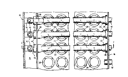
Figure 1 is a h--- ;7.o~ 1 ~oss-section~l view of a dust collectQr; and
Figure 2 is a vertical cross-sectional view along the lines of an din the direction
of arrows 2-2 of Figure 1.
To refer to the drawings, there is shown a dust collect~-r having an outer wall
10. Through the wall 10 pass a numher of air supply pipes 12. A main plate 16 is provided
which is securely a*arhe~l at its perimeter to the outer wall 10. The main plate 16 has a
plurality of openings 18 theLell~Lollgh into each of which is rele~bly located a dust bag 20.
To supply the air to the dust bags 20 there is provided a plurality of blow tubes
22, each of which has a mlmher of do-wnw~dly di~ecled openings 24 - there being one
opening 24 for each bag 20.
To provide a relatively air and dust tight means for the air-to pass from each
supply pipe 12 to its relative blow tube 22 the wall 10 has a seal ~nerally r~ te~l as 26.
The seal 26 has a sleeve 28 which e~t~n~c radially oul~ ily from the tube 22 and a~dally
inwardly from the wall 10. It is concentric with the supply pipe 12. The sleeve 2B f~ms
a cup-like shape with the tube 22. On the inner surface of the sleeve 2B is provided a gasket
30 to seal around the supply pipe 12 and onto which can be forced a first or open end 32
of the blow tube 22. Eref~iably, the open end 32 of the blow tube 22 is of enlarged rliameter
so that it fits over the inner end 34 of the supply pipe 12.
The second end 36 of the blow tube 22 is closed by being flattened, the closing
acting to force all of the air out through the openings 24. An end plate 38 is provided and
which is secured to the main plate 16 and ~n~r~lly parallel to the wall 10. For each blow
tube 22 the end plate 38 has a slot 40 through each of which can pass the ends 36 of the
blow tubes 22.
Again for each of the blow tubes 22 there is provided a means to force the end
32 of the blow tube 22 against the gasket 30. This means co" p. ;.~ ~ a cylinder 42 mounted
on a subsl~ lly vertical shaft 44 p~rallel to but spaced apart from the lon~ n~l axis of

CA 02048847 1998-02-10
the cylinder 42. The shaft 44 is rotdlal)ly mounted in a bracket 14 attached to the main plate
16. The cylinder 42 is secured on the shaft 44 or is i~ th~e~illL. This allows the
cylinder 42 to form a cam effect such that rotation of the cylinder 42 (and the shaft 44)
causes the cylinder wall 46 against end 36 of the blow tube 22 to force end 32 against the
gasket 30. Preferably, a handle 48 is secured to or integral with the shaft 44 to assist the
ro~lion of the shaft 44 and cylinder 42.
Therefore, to remove the dust bags 20, the handle 48 is rotated to cause the
shaft 44 and cylinder 42 to rotate so that the cylinder wall 46 no longer contacts the end 36
blow tube 22. The blow tube 22 can then be moved a~dally to the left to allow end 32 to
dear the wall 28. The blow tube 22 can then be easily removed. This allows removal of the
dust bags 20.
To replace the dust bags 20 and the blow tubes 22 is simply the reverse of the
above ~.oce.lu~e.
Whilst there has been described in the fo~egohlg des~;~lion a p,ef~ed
construction of a dust collector incorporating the principal feal~es of the present invention,
it will be und~slood by those sWlled in the art that many v~n~hons or nto~ ;onc in
details of design or construction may be made without departing from the ambit of the
following claims.

Representative Drawing
A single figure which represents the drawing illustrating the invention.
Administrative Status

2024-08-01:As part of the Next Generation Patents (NGP) transition, the Canadian Patents Database (CPD) now contains a more detailed Event History, which replicates the Event Log of our new back-office solution.

Please note that "Inactive:" events refers to events no longer in use in our new back-office solution.

For a clearer understanding of the status of the application/patent presented on this page, the site Disclaimer , as well as the definitions for Patent , Event History , Maintenance Fee  and Payment History  should be consulted.

Event History

Description Date
Inactive: IPC from MCD 2006-03-11
Time Limit for Reversal Expired 2000-08-09
Letter Sent 1999-08-09
Grant by Issuance 1998-10-06
Pre-grant 1998-03-13
Inactive: Final fee received 1998-03-13
Inactive: Received pages at allowance 1998-02-10
Notice of Allowance is Issued 1997-11-21
Letter Sent 1997-11-21
Notice of Allowance is Issued 1997-11-21
Inactive: Status info is complete as of Log entry date 1997-11-18
Inactive: Application prosecuted on TS as of Log entry date 1997-11-18
Inactive: IPC assigned 1997-11-17
Inactive: IPC removed 1997-11-17
Inactive: First IPC assigned 1997-11-17
Inactive: IPC assigned 1997-11-17
Inactive: Approved for allowance (AFA) 1997-11-06
All Requirements for Examination Determined Compliant 1993-07-14
Request for Examination Requirements Determined Compliant 1993-07-14
Application Published (Open to Public Inspection) 1992-02-15

Abandonment History

There is no abandonment history.

Maintenance Fee

The last payment was received on 1998-07-31

Note : If the full payment has not been received on or before the date indicated, a further fee may be required which may be one of the following

  • the reinstatement fee;
  • the late payment fee; or
  • additional fee to reverse deemed expiry.

Patent fees are adjusted on the 1st of January every year. The amounts above are the current amounts if received by December 31 of the current year.
Please refer to the CIPO Patent Fees web page to see all current fee amounts.

Fee History

Fee Type Anniversary Year Due Date Paid Date
MF (application, 6th anniv.) - standard 06 1997-08-11 1997-07-09
Final fee - standard 1998-03-13
MF (application, 7th anniv.) - standard 07 1998-08-10 1998-07-31
Owners on Record

Note: Records showing the ownership history in alphabetical order.

Current Owners on Record
HOSOKAWA MICRON AUSTRALIA PTY. LTD.
Past Owners on Record
WARREN L. BRAME
Past Owners that do not appear in the "Owners on Record" listing will appear in other documentation within the application.
Documents

To view selected files, please enter reCAPTCHA code :


To view images, click a link in the Document Description column. To download the documents, select one or more checkboxes in the first column and then click the "Download Selected in PDF format (Zip Archive)" or the "Download Selected as Single PDF" button.

List of published and non-published patent-specific documents on the CPD .

If you have any difficulty accessing content, you can call the Client Service Centre at 1-866-997-1936 or send them an e-mail at CIPO Client Service Centre.


Document
Description 
Date
(yyyy-mm-dd) 
Number of pages   Size of Image (KB) 
Abstract 1994-01-20 1 13
Claims 1994-01-20 1 29
Drawings 1994-01-20 2 62
Description 1994-01-20 3 98
Claims 1997-10-14 1 35
Abstract 1998-02-09 1 16
Description 1998-02-09 3 127
Representative drawing 1998-10-04 1 22
Commissioner's Notice - Application Found Allowable 1997-11-20 1 165
Maintenance Fee Notice 1999-09-06 1 179
Correspondence 1997-11-20 1 99
Correspondence 1998-02-09 5 168
Correspondence 1998-03-12 1 38
Fees 1996-07-24 3 99
Fees 1995-06-18 1 65
Fees 1995-08-02 1 57
Fees 1994-07-03 1 43
Fees 1993-06-22 1 34
Prosecution correspondence 1993-10-14 1 46
Examiner Requisition 1995-12-04 2 58
Prosecution correspondence 1996-04-15 1 38
Courtesy - Office Letter 1993-08-19 1 39
Prosecution correspondence 1993-07-13 1 33
Courtesy - Office Letter 1992-02-27 1 46