Note: Descriptions are shown in the official language in which they were submitted.
2048926
gACKGROUND OF TE~E INVENTION
FIELD OF TEIE INVENTION
This invention relat~s to a video signal
recording/reproducing apparatus for recording television
5 signals in a recording media by compressing multiple
fields of the television signal as a unit which is
hereinafter referred to as multiple field unit~ and
reproducing the recorded television signals in norma
play mode, high-speed search mode or slow play mode.
0 DESCRIPTION OF TEE PRIOR ART
To form video recording/reproducing appa-
ratuses (e.g. VTRs, video disc players) for recording
and reproducing the video sig~al, the bit rate reduction
technology (or high efficiency coding technology) has
5 been used to reduce the data quantity of the origina
video signal for a long time video recording. An
example of the bit rate reduction technology is intra-
frame processing. In the intra-frame processing, a two
field unit of the video signal is compres3ed, that is,
20 every frame of video signal. The video signal in a
television signal form is an interlaced signal~ two
fields of which constitutes one frame. By the intra-
frame processing, the video signal is compressed to a
non-interplaced ~orm. The non-interplaced signal has
25 the line to-li_ dista~ce (between scan lines) reduced
2048~26
1 to one-half of that ~or the interlaced signal. ~here-
fore, when a still picture is displayed, the correlation
between line6 is high and the compression is done
ef f iciently . Even when the displayed image is a n~oving
5 picture, compression can be done with high efficiency by
performing motion compensation between two f ields . The
high efficiency in the compression mentioned above is
not unique to the intra-frame processing, but in
general, the compression efficiency will be higher when
10 the processing unit of video signals to be processed
become larger so long as there is no scene change in the
video signal.
Eowever, in conventional video signal
recording/reproducing apparatuses, if compression in
15 multiple field units is applied, expansion in multiple
field units is necessary in reproduction. Therefore,
there is a problem, as described below, in trick plays,
such as slow play and high-speed search.
With reference to processing in a two field
20 units (hereinafter referred to as intra-frame proces-
sing), this problem will be described. Let us first
consider a field array which is reproduced and outputted
for slow play. When the video signal recording/
reproducing apparatus is performing compression and
25 expansion in two field units, the video signal can be
reproduced only in two field units at all times.
Consequently, in slow play, the same frame is output
repeatedly for a specified number of times corresponding
-- 2 --
~ 20~8926
1 to the reproducing gpeed at that time. With regard to
the order of arrangement of fields for a period in which
the same frame is output repeatedly, if the field that
occurs ahead in time of the two fields constituting one
5 frame is named as the former field and the field that
occurs behind in time as the latter field, the former
and latter f ields are displayed alternately on the
screen in such a way as a former fi~ld - a latter field
- a former field - a latter field, and so on. For an
lO array of a former field - a latter field, two fields
having between them a forward time difference w~.ich
corresponds to one field and which is the same as when
visual images were record~d, are displayed with a time
difference placed in forward direction. For an array of
15 a latter field - a former field, two fields having
between them a reverse time difference corresponding to
one field are displayed with a time difference placed in
forward direction. In a picture reproduced in the
forward direction, a time difference in the reverse
20 direction causes a flicker and severely deteriorates the
picture quality of the moving picture.
A case of high-speed search will next be
described. As for the field array of output video
signal, because the operation i9 a high-speed search,
25 intermittent frames are arranged with a certain number
of frames of video signal thinned out according to the
reproducing speed. In a high-speed search in the
forward direction, the order of arrangement of the
-- 3 --
2~48926
1 fields is not reversed as in a slow play in the forward
direction mentioned above. E~owever, though the time
difference between two fields constituting one frame as
one processing unit corresponds to a period of one field
5 when these f ields are recorded the succeeding f ields
which are reproduced just after on the screen are those
which constitute a processing unit af ter passage of a
specified number of frames decided according to the
reproducing speed. Therefore, in a high-speed search,
10 there are mixed field arrays having only a time
difference corresponding to one field and field arrays
having a greater time difference due to the thinning out
of frames for high speed searcn. As has been described,
the presenc~ of t~.e arrays having irregular time
15 differences in reproduc~d pictures is doubtless a big
cause to deteriorate the picture quality in a moving
picture .
From the foregoing description, it will be
understood that in conventional video signal recording/
20 reproducing apparatuses, in trick plays, if the time
difference between fields within one processing unit
differs from the time difference between processing
units, and particularly in a slow play at normal speed
or less, there are intermingled dissimilar time
25 differences in the forward and reverse directions,
substantially deteriorating the smoothness of the motion
of the displayed pictures.
-- 4 --
2048926
1 SUMMA~Y 0~ TE~E INVENTION
The object of this invention is to provide a
video signal recording/reproducing apparatus free from
the impairment of the smoothness of the motion in trick
5 plays, which is caused by compression and expansion of
video signal in multiple f ield units in conventional
video signal recording/reproducing apparatuses.
In order to achieve t~e above object, a video
signal recording/reproducing apparatus comprises
10 compression means for compressing the video signal in
multiple f ield units, recording/reproducing means for
recording the compressed video signal in a recording
medium and reproducing the recorded signal, expansion
means for expanding the reproduced signal in multiple
15 ield units mentioned above, reproducing mode setting
means for setting a desired reproducing speed, recording
medium transportation control means for controlling the
transportation speed of the recording medium to suit
said desired reproducing speed, synchronization detect-
20 ing means for obtaining a field signal by detecting asynchronization pattern from said reproduced signal,
field detecting means for obtaining a reciprocal of a
reproducing speed multiplication factor with respect to
normal 6peed f rom said reproducing speed and making a
25 field period expressed by said reciprocal a continuous
field reproduction period according to said reciprocal
and said f ield signal f rom said synchronization
detecting means, and change-over means for repeatedly
~ 2048926
1 outputting on the 3creen each field of the video signal
in multiple f ield units given by said expansion means
for said continuous f ield period .
Another video signal recording/reproducing
ap~aratus according to this invention comprises
compression means for compre3sing the video signal in
multiple field units, recording/reproducing means for
recording the compressed video signal in a recording
medium and reproducing the recorded 3ignal, expansion
means for expanding the reproduced signal in multiple
f ield units mentioned above, reproducing mode setting
means for setting a desired reproducing speed, recording
medium transportation control ir~eans for controlling the
transportation speed of the recording means to suit said
reproducing speed, synchronization detecting means for
obtaining a field signal by detecting a synchronization
pattern from said reproduced signal, and change-over
means capable of seS[uentially outputting the video
signal in said multiple field units according to a field
signal f rom said synchronization detecting means in
normal reproduction, and also continuously and repeated-
ly outputting one field of signal out of one unit of the
multiple f ield units until signal of the next unit of
the multiple field units can be obtained.
According to the abuve - tioned arrangements
of this invention, even if the video signal is
compressed and expanded in multiple f ield units, the
video signal having a fixed time difference with regard
-- 6
2~48926
1 to the motion of the images in a trick play can be
displayed on the screen, so that a good picture quality
can be obtained with no inadequacy of the motion of the
r eproduced pictur es .
5 BRIEF DESCRIPTION OF TErE DRAWINGS
Fig. 1 is a block diagram of a video signal
recording/reproducing apparatus according to a first
embodiment of this invention and shows the apparatus
processing the video signal in two field units;
Figs. 2, 3 are timing charts showing field
arrays of signal in the constituent elements for
explaining the video signal recording/reproducing
apparatus according to the first embodiment;
Fig. 4 is a block diagram of a video signal
15 recording/reproducing apparatus according to a second
embodiment of this invention and shows the apparatus
performing intra-frame processing;
Figs. 5, 6, 7, 8 are timing charts showing
field arrays of signal in the constituent elements for
20 explaining the video signal recording/reproducing
apparatus according to the second embodiment; and
Fig. 9 is a block diagram showing the internal
construction of a field detecting circuit 8, which is a
component of the video signal recording/reproducing
25 apparatus according to the f irst embodiment .
7 --
2~4892~
DESCRIPTION OF T~E PREFERRED EMBODIMENTS
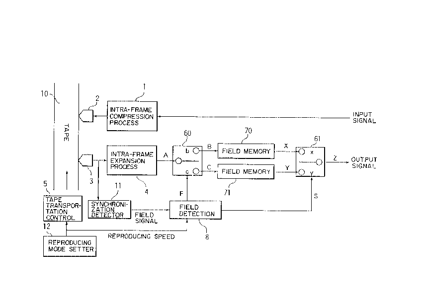
Fig. l is a block diagram of the video signal
recording/reproducing apparatus according to the f irst
embodiment of this invention and the apparatus is a
5 digital video tape recorder (VTR) which uses a magnetic
tape as a recording medium, records and reproduces the
video signal through the compression and expansion
processes in which two f ields, namely, one f ramé of
video signal is handled as a processing unit. Elere, a
10 process treating one frame as a processing unit is
referred to as intra-frame processing.
In Fig. 1, reference numeral 1 indicates an
intra-frame compression process circuit for an Jntra-
frame compression of the input video signal, and 2
15 indicates a recording head which lays down output signal
of the intra-f rame compression circuit on a mag}letic
tape 10 in a magnetization pattern. A video signal re-
cording section is formed by the intra-frame compression
process circuit l and the recording head 2. Reference
20 numeral 3 indicates a preproducing head for reproducing
the signal from the magnetic tape 10, 4 indicates an
intra-f rame expansion process circuit for an intra-f rame
expansion process of the output signal f rom the repro-
ducing head 3, and by these two components, a video
25 signal reproducing section is formed which reconstitutes
the original video signal f rom the signal recorded in
the magnetic tape by the video signal recording section.
Needless to say, the recording head 2 and the reproduc-
204892S
1 ing head 3 are rotating heads mounted on a rotatingcylinder (not shown) on which t~e magnetic head is
wrapped with a specified angle. The aame head may be
used as the recording head 2 and the reproducing head 3.
5 A tape transportation control circui~ 5 has a tape
transfer function (not shown) including a capstan motor,
a capstan, etc. and controls a tape transportation speed
according to a desired reproducing speed in reproduc-
tion. Said desired reproducing speed can be set arbit-
10 rarily by the user of this video signal recording/reproducing apparatus by the use of a reproducing speed
setter 12.
A synchronization detector 11 detects a
synchronization pattern on the magnetic tape 10 from the
15 signal obtained by the reprodlcing head 3, controls a
rotating speed of the rotating cylinder (not shown) so
that the reproducing head 3 optimally traces tracks or
sinks where the magnetization pattern i5 recorded ( this
operation is called tracking), and also detects and out-
20 puts a start timing of frames, each being a processingunit in the intra-frame expansion process circuit 4 and
a start timing of f ields to display the output of the
intra-frame expansion process circuit 4 in field units
on the screen. Reerence numeral 60 indicates a f irst
25 change-over circuit for dividing output signal of the
intra-f rame expansion process circuit to send individual
f ields alternately to two separate systems according to
field signals detected by the synchronization detector
_ g _
` ~ 20~892~
circuit 11. Reference numeral 70 indicate3 a first
field memory for storing output signal from one side of
the change-over circuit 60, and 71 indicates a second
field memory for storing output signal from the other
5 slde of the change-over circuit 60, and 61 indicates a
second change-over circuit for outputting output signals
of the field memories 70, 71 by selectively changing
over their passages. In order to cause a reciprocal of
a reproducing speed multiplication factor set by the
10 reproducing mode setter 12 to be selected as a number of
continuous reproduction of one field, the field select-
ing circuit 8 outputs a field signal F for controlling
the first change-over circuit 60 and a control si~nal S
for controlling the second chan~e-over circuit 61.
Fig. 9 is a block diagram of an example of the
internal construction of the field detecting circuit 8.
A reciprocal setter 80 outputs a forward/reverse signal
for specifying the forward or reverse direction accord-
ing to codes representing a reciprocal of an absolute
20 value of a reproducing speed and the reproducing speed
supplied by the reproducing mode setter 12. ~rhis
reciprocal setter can be realized by use of a Read-Only-
Memory (ROM). By setting one of output signals of the
reciprocal setter 80 as a preset value, a counter 81
25 performs a countdown by using a field signal from the
synchronization detector 11 as a counter clock signal,
sends an underflow pulse as an output signal, and
receives the underflow pulse as a load signal to the
-- 10 --
2048926
1 counter itself. (The preset value is used as an initial
value of the countdown. ) A first flip-flop 82 receives
an underflow pulse provided by the counter 81 as an
input clock signal and gets the inverted output as input
5 data for the first flip-flop itself. A second flip-flop
83 receives the inverted output of the first flip-flop
82 as a clock signal and gets the inverted output of the
second flip-flop as input data for the second flip-flop
itself. A switch 84 operates according to a
lO forward/reverse signal from the reciprocal setter 80.
When a forward/reverse signal denotes the forward
direction, in compliance with the inverted output of the
first flip-flop, the switch 84 sets a control signal S
which is provided by the field detecting circuit 8, and
15 wllen a forward/reverse signal denotes the reverse
direction, in compliance with the inverted output from
the second flip-flop, the switch 84 sets a control
signal S which is provided by the field detecting
circuit 8. A field signal setter 85 operates according
20 to a forward/reverse signal from the reciprocal setter
80. When a ~orward/reverse signal denotes the forward
direction, the field signal setter 85 keeps a field
signal from the synchronlzation detecting circuit 11 its
current state and outputs a field signal F. When a
25 forward/reverse 3ignal denotes the reverse direction,
the field signal setter 85 operates according to two
kinds of state of output signals of the flip-flop 83.
When the output signal is in one of the two states, the
-- 11 --
2048926
1 field signal setter 85 keep3 the current state of field
3ignal f rom the synchronization detector 11, and outputs
a field signal F, and when the output signal is in the
other of the two states, the field signal setter 85
5 inverts a f ield signal f rom the synchronization detector
11 and outputs an inverted field signal F. This field
signal setter can be realized easily by a ROM, but can
be realized very easily by using a logic circuit or a
swi tch .
The operation of the above-mentioned arrange-
ment of the present embodiment will be described with
reference to a timing chart showing field arrays of
signal at various component of the present embodiment in
Fig. 2. Fig. 2 presents an example showing an operRtion
15 at 1/3 normal speed among trick play functions of VTR.
In Fig. ~, signal A denotes output of the intra-frame
expansion process circuit 1 in Fig. 1, which proceeds
from left to right on time base. The numbers in the
signal A show f ield numbers of video signals recorded in
20 the magnetic tape, and one box corresponds to a period
of one field. In this embodiment in which intra-frame
processing is performed, in the signal A, signals for
one f rame are always included in one f rame period .
Since the operation is performed at 1/3 normal speed,
25 data for one frame is output repeatedly and continuously
for a period of three frames.
Conventionally, this signal P~ is outputted on
the screen, so hat a s~quentlal field array is reversed
20~8926
1 at 30me points in every three-frame period. For
example, in Fig. 2, this occurs where signals of a field
1 are followed by signals of a f ield 0 .
In this embodiment, by field signals of F from
5 the field detecting circuit 8, the first change-over
circuit 60 divides the output signals of A of t~.e intra-
frame expansion process circuit 1 into even fields and
odd fields, which are signals B and C. In Fig. 2, the
field signals of F are denoted by b where the fields are
10 even fields, and by c where the fields are odd ~ields.
In other words, the first change-over circuit 60 outputs
an even field signal B when the field signal F is b and
an odd field siynal C when the field signal F i8 C.
Description will now be made cf the first change-over
15 circuit 60, and the field memories 70, 71. The field
memories 70, 71 have the same addresses for writing and
reading data, and the write/read addresses for one field
have only to be repeated. As for write and read timing,
in one address period data provided by the f irst change-
20 over circuit 60 is written and read, that is to say, theso-called read-after-write operation is performed. The
first change-over circuit 60 operates as if it gives
write enable/write inhibit control signals to the field
memories 70, 71. More specifically, when a field signal
25 F is b, the field memory 70 is write enabled, while the
field memory 71 is write inhibited. Conversely, when a
field signal F is c, the field memory 70 is write
inhibited, while the field memory 71 is write enabled.
-- 13 --
2048926
1 Therefore, the field memory 70 receives signal B which
is judged to be even f ields by the f irst change-over
circuit 60. During an even field period, a signal B is
written in the memory and at the same time, the signal B
5 is output. On the contrary, during an odd field period,
the field memory 70 is write inhibited, so that the
signal B stored in the field memory 70 is outputted
again. This signal outputted ~rom the field memory 70
is referred to as a signal X. Signals X are always even
10 f ield signals as shown in Fig . 2 .
On the other hand, the f ield memory 71
receives signal C judged to be odd fields by the first
change-over circuit 60, and during an odd field period,
writes a signal C in the memory and outputs the signal C
15 at the same time, but during an even field period, ~he
field memory 71 is write inhibited, and therefore, again
outputs the signal C which has been stored therein.
Accordingly, if output of the field memory 71 is denoted
as signal Y, f ield signals of signal Y are always odd
20 field 8ignalS.
The second change-over circuit 61 selects
either one of a signal X and a signal Y and outputs a
3ignal Z to be displayed on the screen, and for this
selection, uses a control signal S provided by the field
25 detecting circuit 8. Fig. 2 shows that a control signal
S is x for selection of a signal X and y ~or selection
of a signal Y. Control signal S is provided by the
field detecting circuit 8. The field detecting circuit
-- 14 --
,~oc~
1 8 causes a reciprocal of a mul~clp~ication index of
reproducing speed to be selected as a number of
continuous reproduction of the same ield by the second
change-over circuit. Since the reproducing speed is l/3
5 of normal speed, a reciprocal 3 is found, and signals of
each field are reproduced at intervals of three fields.
Fig. 2 shows the signals of signal Z consist-
ing of field arrays of signal to be reproduced on the
screen. Unlike the signal A, in the signal F, there are
10 no field arrays, which are outplltted in a backward
sequence in time with respect to the input signals in
recording, so that a remarkable advantase of this
technique is that the displayed pictures are free of
flicker in slow play mode.
The reproducing operation at -1/3 of normal
reproducing speed in this embodiment will be described
with reference to a timing chart showing the field
arrays of signal at various . _--A ts. The signals of
the output signal A of the intra-f rame expansion process
20 circuit 4 when the reproducing speed is -1/3 of normal
speed are the same as in the abo~ tioned reproduc-
tion at l/3 of normal speed in respects of the way in
which fields are arrayed in a frame as one processing
unit and the continuous reproduction of one processing
25 unit at an interval of three frames. The difference is
that since this operation is reproduction in the reverse
direction, the order in which the frames are taken by
the tape-head system is a descending order of field
-- 15 --
2048926
1 numbers as shown in the signal A. In the prior art,
even though this operation is reproduction in reverse
direction, there are field arrays in one of which there
is a time difference of three fields, including one
5 field in forward direction and one field in reverse
direction. (e.g. from field 5 to field 4, from field 5
to f ield 2 )
In this embodiment, in a reverse reproduction,
the operation of the signals F and S provided by the
10 field detecting circuit 8 differs from that in Fig. 2.
First with regard to the signal F, as has been described
of the internal construction o~f the field detecting
circuit 8, the sequence of b a~d c is reversed when
necessary according to the reproducing speed instead of
15 alternately selecting b and c in ,~ nce with the
occurrence of even fields and odd fields. In the
reproduction at -1/3 of normal speed, the sequence of b
and c, which represent even and odd fields, is reversed
at every three frames. This number three is a
20 reciprocal of 1/3 of normal speed ( the signal F in
Fig .3). With regard to the signal S, as with the
signal F, the selection of output o the field memory 70
and the field memory 71 (signal X and signal Y) is
reversed every three frames. A field signal selected by
25 the 6econd change-over circuit 61 according to a signal
S is a signal Z corresponding to an odd f ield in two
fields of one processing unit. Since this operation is
reproduction in reverse direction, if signal3 are
-- 16 --
2~4892~
proce8sed in multiple f ield units, the number of f ields
of which is greater than in intra-frame processing, it
is nothing other than outputting f ield signals starting
with a field signal of the largest field number (i.e.
5 the last field signal of all field signals recorded in
video recording).
According to the signals F and S provided by
the field detecting circuit 8 described above, the field
arrays in the signals B, C, X, and Y are as shown in
10 Fig. 3, so that the field arrays of signal Z, which are
outputted on the screen, have a constant inter-f ield
time difference of one field (except for field arrays
without time difference) even in slow play in reverse
direction, with the result that a fine picture quality
15 i8 obtained in slow play.
Fig. 4 is a block diagram o~ the video signal
recording/reproducing apparatus according to a second
embodiment of this invention, and this apparatus is a
digital VTR which uses a magnetic tape as a recording
20 medium a8 in the fir8t embodiment degcribed above and
performs video recording and reproduction by compression
and expansion processes in intra-frame processing. In
Fig. 4, a intra-frame compression process circuit 1, a
recording head 2, a reproducing head 3, a intra-frame
25 expansion process circuit 4, and a tape transportation
control circuit 5 have the same functions and operates
in the same way as in the first embodiment, only
difference lying in a change-over circuit 62 and a field
-- 17 --
204892~
1 memory 72. The 3econd embodiment of this invention will
be described in the following.
Fig . 5 is a timing chart showing the f ield
arrays of signal at various components of a reproducing
5 system operated at 1/3 of normal speed as in the f irst
embodiment when the video signal recording/reproducing
apparatus according to the second embodiment is used.
Signal A shows output signals of the intra-f rame
expansion process circuit 4, which signals are composed
Of reeetitions of three consecutive f rames of the same
kind, each frame being one processing unit. The change-
over circuit 62 is controlled bi~ a field signal F, and
transfers signals of signal A mentioned above as signal
D to the field memory 72 at the subsequent stag~ only
when a f ield signal F is an even f ield. Signals D
output by the change-over circuit 62 are shown in Fig.
5. Only when a field signal F is an even field, the
change-over circuit 62 outputs a signal D, so that even
f ield signals of signal F are shown in Fig . 5 .
The field memory 72 performs a read-after-
write function as in the field memories 70, 71 in the
first embodiment described above, and has the change-
over circuit 62 operate to issue write enable/write
inhibit control signals to the field memory 72. In a
period when the field memory F is d and the change-over
circuit 62 outputs a signal D, the field memory 72 is
write enabled. In a period when a signal D is not
output, the field memory is write inhibited. Therefore,
-- 18 --
2048926
1 when a 5ignal D is applied to the ~ield memory 72, the
field memory 72 has the signal D written therein and
outputs the signal D at the same time . When a f ield
signal F is an odd signal and a signal D is not output,
5 the field memory 72 again outputs a signal D which has
been stored. Output of the field memory 72 are shown as
signal D in Fig. 4. In contrast to the first embodi-
ment, the signal ~ i3 composed of signals representing
even fields, so that there are no fields which are
10 outputted in a backward sequence in time as in the prior
art .
Description will then be made of a slow play
in reverse direction. Fig. 6 is a timing chart showing
field arrays of signal at various components for
15 explaining the operation in reproduction at -1/3 of
normal speed. In third embodiment only even fields are
outputted on the screen as described, there are no
forward ~ield arrays in reverse reproduction between any
two fields constituting a frame as one processing unit,
20 50 that there is no possibility of reverse field arrays
being disturbed in the signal Z in Fig. 6.
The operation of reproduction at speed twice
faster than normal speed in this second ~ ~ir-nt will
be described with reference to a timing chart of Fig. 7
25 showing field arrays o~ signal in the various com-
ponents. For the output signal A of the intra-~rame
expansion process circuit 4 in reproduction at twice
faster speed, unlike in reproduction at 1/3 of normal
-- 19 --
20 48926
1 speed, data of all frames (data of all fields) cannot be
obtained f rom the tape-head system but only data of
every other frame can be obtained. Therefore, the
numbers of signal A are arrayed as shown in Fig. 7.
In a system in which intra-frame processing is
performed as in this embodiment, even in high-speed
search faster than normal speed, an expansion process is
carried out in frame units, so that the fields are
arrayed in frame units for the signal A. Accordingly,
if signal A is reproduced on the scree~ as it is like in
the prior art, there are bound to be field arrays which
have dissimilar time differences between fields.
Referring to Fig. 7, signals are reproduced in frame
units starting with the leftmost frame, and a time
difference corresponding to one field i8 placed bet een
field 0 and field 1 in reproduction. E~owever, betw2en
field 1 and field ~, there is a time difference corre-
sponding to three fields. To put differently, in the
reproduced pictures on the 3creen, a time difference of
one field and a time difference of three fields occur
alternately. This rhPn~ ~nnn does not become a problem
when only video signals of still pictures are recorded.
In video recording/reproducing apparatuses for recording
video signals of moving pictures, 3uch as a VTR, the
irregularity of time difference between fields will
result in producing pictures giving the viewer an
uncomfortable 3ensation.
-- 20 --
2Q48926
In this second embodiment, by the use of the
change-over circuit 62 operated by a signal F to receive
the signal A mentioned above, the signal D gathered by
taking even fields only and the signal Z outputted from
5 the field memory 72 are arrayed as shown in Fig. 7. By
looking at the signal Z of Fig. 7, it is understood that
there are two kinds of time difference, that is, there
are some field~ which have no time difference and other
fields which have a time difference corresponding to
10 four fields. ~rhe field arrays with no time difference
are of complete still pictures, and therefore, those
field arrays are equivalent to the field arrays with
only a time difference of four fields, and they do not
produce reproduced pictures which give the view~r an
lS uncomfortable feeling.
Fig . 8 is a timing chart showing the f ield
arrays of signal in the various n~nts in reproduc-
tion at speed -2 times a3 fast as normal speed, which
indicates the operation of this embodiment in high-speed
20 search in reverse direction. In this case, too, since
only even fields are reproduced in this embodiment,
there is no possibility that the reverse field arrays
are disturbed in the signal Z, so that this embodiment
will contributes to improving the picture quality in
25 high-speed search.
As described above, by the arrangement of this
embodiment, only time difference between processing
units is shown in reproduced pictures even in high-speed
-- 21 --
2048926
1 8earch. The video 8ignal is fQrmed with a fixed time
difference for moving pictures, 80 that the video signal
can be reproduced to form moving pictures with fine
picture quality.
If a reciprocal of a reproducing speed
multiplication factor is not an integral number, the
reciprocal setter 80 in the internal composition of the
field detecting circuit 8 of Fig. 9 may be arra~ged to
output an integral number most close to a reciprocal
which is not an integral number. T~en, a number of
continuous reproduction of a f ield signal can be made an
integral number easily. In a hlgh-speed search at
higher speed th~n normal speed, a reciprocal of a
multiplication index of reproducing speed is less than
l. In this case, as described with reference to the
second embodiment, all f ield data recorded in t~.e tape
cannot be retrieved. Thereore, by arranging the
reciprocal setter 80 to always output l as a reciprocal
of any output signal when the reproducing speed is
higher than normal speed, a number of times of reproduc-
tion of each field is made one, resulting in the same
conventional reproduction operation in frame units. So,
it is only necessary to use a method of the second
embodiment which outputs only one field from each
processing unit in high-speed search. In a case where
one processing unit is a plurality of frames, the first
embodiment can be applied to reproduce one of the fields
of each frame within one processing unit.
-- 22 --
2~48926 =
In the arrangements of the f irst and second
embodiment (Figs. 1, 4), the field memories (70, 71, 72)
are provided separately from the intra-frame expansion
proces3 circuit 4. ~owever, the intra-frame expansion
5 process circuit 4 processes two fields at the same time,
and when the process result is outputted on the screen,
signals are outputted in frame units. Therefore, at
least one or more field memori~s are provided. Even if
input signals into the field memories 70, 71, 72 are not
10 divided into fields, it is only necessary for data
stored in each f ield memory to be separated into f ields .
The field memories 70, 71, 72 are compatible with the
field memory in the intra-frame expansion process
circuit 4. The operation of the intra-frame expa~sion
15 process circuit 4 described with reference to the
embodiments of this invention is performed in frame
units . E~owever, two f ields constituting one f rame of
the output signal A have been separated before they are
output. The separated state of fields i8 achieved by
20 geparating data extending over two fields into ordinary
f ield arrays through write and read operations of the
f ield memory with a memory capacity of one or more
fields in the intra-frame expansion process circuit 4.
Therefore, by matching the operation of the field
25 memories 70, 71, 72 and the change-over circuits 60, 62
according to this invention with the write and read
operations in the intra-frame expansion process circuit
4, data to be stored in the field memories 70, 71, 72
-- 23 --
2~48926
1 can be eaBily 8eparated into fields. In the field
memories according to this invention, input signals need
not necessarily be separated into fields, but it is only
necessary to have the signals separated into f ields when
5 they are outputted and eventually displayed on the
screen in such a way that a number of fields continue
which corresponds to a reciprocal of the multiplication
index of the reproducing speed and a number of f ields as
one processing unit. ~he second embodiment is much
10 easier. Whatever is the number of fields as one
processing unit, in trick plays by continuously out-
putting only one field out of one processing unit on the
screen, the fields can be arrayed in a predetermined
form for reproduction both in forward and reverse
15 directions.
-- 24 --