Note: Descriptions are shown in the official language in which they were submitted.
~(~496S9
Title: Ultrasonic Cuttina SYstem for Stock Material
Field of the Invention
The present invention relates to an ultrasonic cutting
~ystem for stock material, and in particular to an ultrasonic
cutting system employing a blade adapted to ultrasonically cut tire
stock material at a low angle.
Backaround
A tire typically includes plies of variou~ types, including,
for example, an inner ply. These plies may be formed from a long
sheet of rubber stock material by cutting the stock material to
appropriate lengths and folding the end portions together to form
a generally annular shape adapted to become part of a tire carcass.
The two end portions of the ~tock material are typically overlapped
a small amount and may be bonded together, for example, by
adhesively bonding, or "stitching" the end portions together under
pressure. The overlap of the ply ends results in a limited
circumferential portion of these plies having a slight radial build-
up, which cannot be avoided with known cutting techniaues.
Currently, when a sufficient length of stock material has
been prepared for cutting, the stock material is supported on a
processing table and the blade is forced into the material. The
blade is moved across the width of the stock material to cut off the
desired length of material. The stock material is typically formed
from rubber based products which are flexible and ~sticky~ to the
touch. When the stock material is being cut with a conventional
blade, the material tends to move or vibrate as the blade traverses
the material, the~eby increasing the cutting time and decreasing the
auality of the cut. Moreover, the blade must cut the stock material
at an angle substantially perpendicular to the processing table, or
the stock material will tend to bunch up in front of the blade. The
perpendicular angle of cut results in a cut edge having a reduced
surface area, thereby making it difficult to splice the cut surfaces
to one another in the tire building process. Conseauently, it is
necessary to overlap the ply end portions a ~mall amount and
adhesively bond or "stitch" them together under pressure.
`20496~
Other cutting techniques are generally known but have not
been successfully applied to stock material cutting. For example,
ultrasonic cutting has been used for cutting textile material as
shown in U.S. Patent No. 4,711,693 issued to Holze, Jr. The Holze
patent shows an anvil comprising an elongated, substantially
rectangular housing in which a piston is disposed for motion
relative to the housing. The anvil includes a slitting implement
advanced by the piston. The textile material is fed through the nip
between the slitting implement and ultrasonic horn. The ultrasonic
horn is undergoing vibratory motion to cut the textile material held
thereagainst.
Additionally, it is known that attempts have been made to
cut tire sidewall material with a conventional blade at angles as
small as 23 with respect to the horizontal, and then splice the cut
ends together with a bevel lap splice. However, it has been found
that a bevel lap splice of 23 or more in a sidewall does not adhere
well without additional glues or adhesives and can become separated
under normal tire operating conditions.
Summary of the Invention
The present invention relates to an ultrasonic cutting
system having a blade adapted to ultrasonically cut stock material
at a low angle. An ultrasonic cutting cystem according to the
present invention comprises a processing table, a carriage assembly
adapted to move transversely across the width of the processing
table, and an ultrasonic cutting tool mounted on the carriage
assembly.
The processing table has an anvil incorporated therein.
According to one aspect of the invention, the anvil comprises two
parallel strips of plastic or Lexan material mounted on a beam or
base. The parallel strips extend across the width of the anvil and
define a guide channel therebetween for slidably receiving and
guiding part of the carriage assembly.
The carriage assembly of the ultrasonic cutting system is
adapted to move transversely across the anvil on two stationery
parallel rods positioned above the anvil. The rods respectively are
--3--
~0~96~9
received in and pass through bearing blocks, which are part of the
main carriage body of the carriage as~embly.
The carriage assembly also includes a set of rollers which
are mounted on the distal ends of arms extending downwardly from the
carriage body. The set of rollers includes a first and second roll-
er, wherein the second roller is located between the blade and the
first roller. The rollers are adapted to travel ahead of the blade
as the carriage traverses the stock material, with the first roller
leading the second roller. The two rollers apply a predetermined
amount of downwardly directed pressure on the stock material to
removably bond or "stitch" the stock material to the anvil
positioned therebelow.
The carriage assembly includes an ultrasonic cutting
apparatus having a transducer and a cutting blade. The transducer
and blade are mounted toward the side of the carriage body and
extend at an angle downwardly therefrom. The cutting apparatus is
part of, and moves concurrently with, the carriage assembly as it
traverses the stock material. The transducer produces ultrasonic
energy which is applied to the blade to create compression waves
axially therealong.
The ultrasonic cutting apparatus is mounted on the carriage
such that the blade extends at a low angle, preferably at an angle
of about 50 to lOo with respect to the horizontal. The blade is
also offset forwardly from the carriage assembly at an angle of
approximately 150 relative to a normal or transverse plane across
the carriage assembly. The low angle of the blade creates a beveled
cut having a width of between about 1.00 cm and 2.88 cm. When the
blade is brought into contact with the ~tock material, the
oscillating blade cuts cleanly through the material.
The carriage assembly may further include a substantially L-
shaped shoe extending downwardly therefrom. The shoe travel~ behind
the blade when the carriage is moving across the anvil, and is
adapted to lift and remove the cut portion of the stock material
from the anvil. The bottom portion of the shoe includes a
downwardly extending guide projection slidingly received in the
2~6~`~
anvil guide channel to maintain the alignment of the
carriage assembly with the anvil and processing table.
By providing an ultrasonic cutting system that uses
ultrasonic energy to cut stock material, a low angle cut of
the stock material can be achieved. The low angle cut
results in a cut edge having an increased and "tacky"
surface area, which facilitates splicing the cut surface of
the stock material together with a bevel lap splice without
using additional glues or adhesives. The bevel lap splice
provides for a substantially seamless bond of the stock
material and eliminates radial build-up along the seam.
Moreover, the bevel lap splice improves the balance of the
tire and reduces both the radial forces on the splice and
the tire cure time. Additionally, the material savings in
eliminating the end ply overlap reduces the overall cost of
the tire.
Generally speaking, and in summary of the foregoing,
the present invention may be considered as a method for
ultrasonically cutting stock material, comprising the steps
of: mechanically coupling a blade to an ultrasonic
transducer to form an ultrasonic cutting tool; mounting the
ultrasonic cutting tool on a carriage assembly; securing
the stock material to an anvil; resonating the blade with
ultrasonic energy travelling longitudinally therethrough;
moving the carriage assembly transversely across the width
of the stock material; and cutting the stock material with
the blade as the carriage assembly traverses the stock
material.
The above method may be carried out by way of an
ultrasonic cutting apparatus for rubber stock material,
comprising: means for temporarily securing the stock
material to an anvil; a carriage assembly movable across
the width of the anvil; and an ultrasonic cutting tool
mounted on the carriage; the cutting tool having a blade
mechanically coupled thereto, the blade having means for
resonating in response to ultrasonic energy travelling
VLS:in -5-
C
Z ~ 4 ~ , 9
longitudinally therethrough; wherein when the carriage
assembly moves transversely across the anvil, the blade
cuts through and across the stock material, the carriage
assembly further including a shoe slidably engaging the
stock material at a location behind the blade to separate
the stock material from the anvil after the blade has cut
the stock material, the shoe having a projection slidably
moving within a guide channel formed in the anvil.
Further objects and advantages of the present
invention will become apparent from the following detailed
description and accompanying drawings.
Brief Description of the Drawing~
In the drawings:
Fig. 1 is a diagonal upstream perspective of the
ultrasonic cutting system constructed according to the
present invention, with the stock material and rod support
structure being omitted for clarity of illustration;
Fig. lA is a cross-sectional side view of the overlap
splice of a prior art tire;
Fig. lB is a cross-sectional side view of the
crush-cut splice of a prior art tire;
Fig. lC is a cross-sectional side perspective view of
the low angle bevel lap splice provided by the present
nvention;
Fig. 2 is a side, upstream perspective view of the
ultrasonic cutting system;
Fig. 3 is a plan view of the carriage assembly shoe
taken along the plane 3-3 of Fig. 2;
VLS:in -5a-
` 20~6~3
Fig. 4 is a side view of the shoe taken along the plane 4-
4 of Fig. 3;
Fig. 5 is a diagonal downstream perspective of the
ultrasonic cutting system;
Fig. 6 i8 a diagonal downstream perspective of the
ultrasonic cutting system, similar to but enlarged from Fig. 5,
showing the blade ultrasonically cutting the stock material;
Fig. 7 is a diagonal downstream perspective of the
ultrasonic cutting system taken from a different angle, showing the
blade ultrasonically cutting the stock material;
Fig. 8A is an elevation of the cutting apparatus of the
ultrasonic cutting system with the transducer and suspension
assembly being shown in hidden lines;
Fig. 8B is a detailed side view partially in section of the
cutting apparatus, similar to but enlarged from Fig. 8A, having the
housing removed for clarity;
Fig. 8C is an end elevation of the cutting apparatus taken
along the plane 8C-8C of Fig. 8B;
Fig. 9 is a perspective view of an alternative anvil
embodiment;
Fig. 10 is an end elevation of the anvil of Fig. 9 showing
the details of the stock material stripper bar;
Fig. 11 is a side upstream perspective view of an additional
embodiment of the ultrasonic cutting system;
Fig. 12 is a diagonal downstream perspective of the
ultrasonic cutting system of Fig. 11;
Fig. 13 is a diagonal downstream perspective of the
ultrasonic cutting system of Fig. 12, with portions removed for
clarity and with a blade stabilizing assembly added; and
Fig. 14 is schematic elevation of the disconnect member of
the quick connection system for the cutting tool.
20496~9
DETAILED DESCRIPTION OF THE PRErr;nR~ EM80DIMENT
As described above, the present invention relates to an
ultrasonic cutting system, indicated generally at 1, having an
ultrasonically energized blade adapted to cut stock material at a
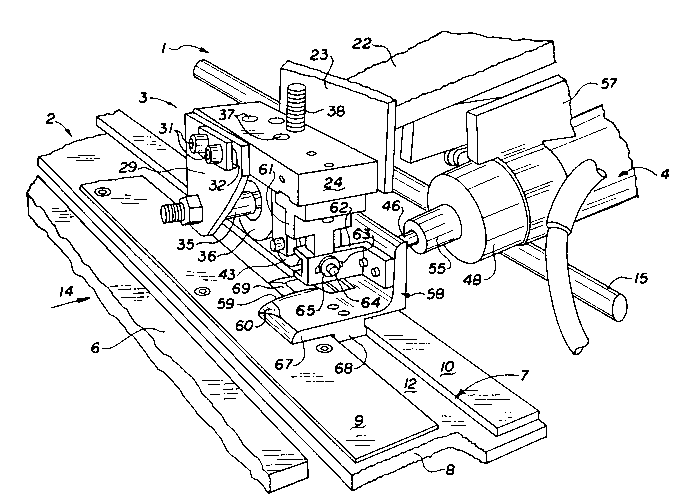
low angle. As shown in Figs. 1, 2 and 5, an ultrasonic cutting
system 1 according to the prevent invention comprises a processing
table, indicated generally at 2, a carriage assembly adapted to move
transver6ely across the width of the processing table, indicated
generally at 3, and an ultrasonic cutting tool mounted on the
carriage assembly, indicated generally at 4.
The processing table 2 of the cutting system i6 normally
located in a stock material processing line. The proce~sing table
2 supports the stock material as it is fed from the stock material
supply through the cutting station. At the cutting station, the
stock material is cut into lengths, which are then formed into a
tire ply for incorporation into a green tire as it is being built.
As shown in F~g. 1, the processing table 2 includes a feed
table 6 and an anvil, indicating generally at 7, mounted in end to
end relationship to one another. In one embodiment, the anvil 7
includes a base 8, a front strip 9 and a back strip 10 of pla~tic
or Lexan material. These parallel strips 9, 10 extend across the
width of the base 8 and are secured to the top of the base 8 by
screws or other conventional means. The parallel strips extend
across the anvil 7 in close proximity to one another to form a guide
channel therebetween, as shown at 12. The top surfaces of strips 9
and 10 preferably lie in a common plane with the top surface of feed
table 6.
The feed table 6 may include a cor,veyor for automatically
advancing stock material 13 to the anvil at the cutting station.
The stock material 13 is advanced in the longitudinal direction of
arrow 14, with the term "upstreamn -aning to the left of the
cutting station, and the term "downstream" meaning to the right of
the cutting station, as viewed in Fig. 1. The stock material 13
downstream of the cutting station may be supported by a rotatable
` ~)4~59
shaft 15 as shown in Fig. 7, or by a downstream, run-out table (not
shown). The shaft 15 or run-out table form part of the overall
processing table.
As shown best in Fig. 5, the carriage assembly 3 of the
ultrasonic cutting system is adapted to move transversely across the
anvil 7 on two parallel and transversely exten~ing rods 17 and 18
positioned above the table. The rods respectively pass through
bearing blocks 19 and 20 on the carriage assembly. The bearing
blocks contain bearings therein to permit the carriage assembly 3
to selectively move along the rods 17, 18 transversely across the
width of the stock material 13. The lateral -Vl -nt of the
carriage assembly along the rods is controlled by a conventional
motor, such as a servo motor (not shown), which can be either
mounted on or near the table or on the carriage assembly.
The carriage assembly 3 further includes a carriage body 22,
as best shown in Fig. 5. The carriage body 22 extends transversely
between and is fixedly secured to the bottom of bearing blocks 19
and 20.
A vertically extending hanger 23 is connected to and extends
downwardly from the upstream end of the carriage body 22. A support
plate 24 is secured to and extends horizontally outwardly from the
bottom of hanger 23. The support plate 24 can be selectively
transversely adjusted relative to hanger 23. For this purpose, and
as best shown in Fig. 5, the hanger has elongated slots 26 therein
respectively receiving bolts 27 on the support plate to allow
selective transverse adjustment of the support plate 24 relative to
the hanger 23. Nuts 25 on bolts 27 may be selectively drawn down
against vertically extending hanger 23 to secure the support plate
24 in the selected transverse position relative to the vertically
extending hanger 23.
As shown in Fig. 2, the support plate 24 has a roller
support flange 29 secured to the upstream end thereof. The
vertically extending flange 29 may be transversely adjusted relative
to the support plate 24. For this purpose, spaced bolts 31 on the
`. 20~9653
upstream end of the support plate 24 are received in a horizontal,
elongated slot 32 in the upper end of flange 29. Nuts 30 on bolts
31 may be selectively drawn down against backup member 33 to secure
the roller support flange 29 in the selected transverse position
relative to ~upport plate 24.
The support flange 29 has a first roller shaft 35 mounted
thereon adjacent the bottom thereof. Roller shaft 35 extends
through a mounting hole in support flange 29 and is secured thereto
to mount roller shaft 35 above and in a parallel relationship to
strip 10 of anvil 7. A first, relatively wide roller 36 is
rotatably mounted on shaft 35. The roller 36 preferably has a
number of outwardly extending ribs extending circumferentially
therearound. The first roller 36 applies pressure to the stock
material 13 positioned between the first roller 36 and the anvil 7,
as will be described in more detail hereinafter.
As shown in Fig. 1, the support plate 24 has a plurality of
tapped holes 37 extending therethrough to selectively receive a
threaded shaft 38 in the selected po~ition relative to the anvil.
The height of the shaft may be adjusted upwardly or downwardly
relative to support plate 24 by turning the shaft in one direction
or the other. As shown in Fig. 2, the bottom of shaft 38 has a
yoke 39 mounted thereon which extends downwardly therefrom. The
yoke 39 includes two parallel and downwardly extending arms 40, 41.
A second roller shaft 42 extends between and is mounted to
downwardly extending arms 40, 41. The roller shaft 42 iB above and
in parallel relationship to the strip 10 of anvil 7. A second,
relatively narrow roller 43 is rotatably mounted on second roller
shaft 42. The ~econd roller 43 applies concentrated, downwardly
directed pressure to the stock material 13 positioned between the
second roller 43 and the anvil strip 10, as will be described in
more detail hereinafter.
The rollers 36, 43 may additionally include a spring bias to
increase the downward pressure on the stock material. For example,
if the yoke is slidably mounted on shaft 38, a spring 44 can be
~0~9~59
inserted between the yoke 39 and support plate 24 to bias roller 43
downwardly toward the anvil. The spring 44 is adapted to maintain
a predetermined downward pressure on the anvil 7, yet be flexible
enough to allow the yoke to be raised to insert the stock material
between the second roller 43 and the anvil.
As shown in Fig. l, the rollers 36 and 43 are spaced a
predetermined distance apart from each other, with each roller
having an edge aligned with the inside edge of the back strip 10 of
anvil 7, on the side closest to the carriage guide channel 12. As
the carriage assembly 3 moves transversely across the anvil 7, each
roller 36, 43 is adapted to roll across strip lO with the inside
edges of the rollers being in alignment with the inside edge of the
strip lO. The rollers are located at a position on the carriage
assembly such that the first roller 36 is adapted to provide the
initial, general stitching of the stock material 13, while the
second roller 43 is adapted to provide a localized stitch of the
stock material 13, just slightly ahead of a blade 46 on the
ultrasonic cutting tool 4.
The first and second rollers provide sufficient downward
pressure on the stock material 13 to temporarily bond or "stitch"
the material to the anvil 7. The stock material 13 is typically
formed from petroleum-based products which are "sticky~ or "tacky"
to the touch, and hence can be temporarily adhesively bonded to a
surface. Adhesively bonding the stock material just ahead of the
blade permits the blade 46 to traverse the stock material at a low
angle without the material moving or vibrating. Moreover, after the
blade 46 has traversed the stock material 13, the material may be
easily removed from the processing table by merely "peeling" it
away.
As shown in Fig. 8A, the blade 46 has sharpened edges and is
mechanically coupled to a transducer, indicated generally at 47,
within a housing 48. The transducer 47, blade 46 and housing 48
together cooperatively form an ultrasonic cutting tool 4 which is
mounted toward the side of the carriage assembly 3. The cutting
--10--
` 2(3 ~96~9
tool moves concurrently with the carriage assembly 3 as it traverses
the stock material.
The transducer 47 consists of a crystal stack, indicated
generally at 50, and a horn 51 which are coupled together by a stud
bolt (not shown). The stack 50 and horn 51 are mounted within the
transducer housing 48 by a suspension assembly, indicated generally
at 53, which insulates the housing from the ultrasonic energy. As
shown in detail in Fig. 8B, the ~uspension assembly 53, for example,
includes an outer ring 54, an inner ring 52 and two 0-rings 45,
disposed between the inner ring and opposite sides of flange 51a on
the horn. The outer ring has four tapped bores 65A (Fig. 8C~
therein spaced 90 apart from one another. The four tapped bores
65A are respectively in radial alignment with four circumferentially
spaced bores 65B in inner ring 52 and four circumferentially spaced
bores 65C in the horn 51.
As shown in Fig. 8C, four pins, indicated generally at 66,
disposed 90 apart from each other, extend radially inward in
aligned bores 65A-C from the outer ring 54 into the horn 51. The
pins 66 have threaded heads 66A at their radially outer ends to
allow the pins to be held in position by the threaded connection
between the heads 66A and the tapped bores 65A. This threaded
connection on the pins secures the suspension assembly 53 to the
horn 51 and prevents the horn 51 from rotating within the suspension
assembly 53.
The outer ends of the heads 66A of pins 66 are received
within the confines of bores 65A to help p.even~ ultrasonic energy
loss through the pins to the suspension asse~mbly 53. Further, the
suspension assembly 53 is located at a position along the transducer
47 that corresponds to an ultrasonic energy nodal point, such that
a i n i ~um amount of energy is lost by transmission through the
suspension assembly 53.
The horn 51 of the transducer 47 extends forwardly from its
coupling with the stack and narrows down to a forward necked end,
shown generally at 55 in Fig. 8A, a portion of which protrudes from
204965~
the transducer housing. A holder 55a is mechanically coupled to the
necked end 55 by a stud bolt (not shown). The holder 55a has a
blind end bore (not shown) in the forward end which is adapted to
receive the rear end of blade 46. The blade 46 is mechanically
soldered within the blind end bore by conventional processes.
The crystal stack 50 is ultrasonically driven by a set of
piezo-electric crystals, shown generally at 56, which are located
at the end of the crystal stack 50 and which are mechanically
coupled thereto by compression bolt 56a. The crystals 56 are
typically formed from PZT8 material. The crystal stack 50 is of the
type commercially available, such as that available from Branson
Ultrasonics.
In the preferred form of the invention, the crystals 56 are
driven with square waves and are adapted to produce oscillations in
the 40 Khz range in the crystal stack. The oscillations produce
ultrasonic compressive energy waves axially down the crystal stack
50, horn 51 and holder 55a, and subsequently down the blade 46. The
horn 51 can be tuned so that the ultrasonic energy produces standing
waves along the blade 46 having a maximum near the point that the
blade is adapted to enter the stock material 13. Accordingly, when
the blade 46 contacts the stock material, the oscillating blade
cleanly cuts through the material.
As shown in Fig. 6, the ultrasonic cutting tool 4 is fixedly
mounted to the carriage assembly 3 by bracket 57. Bracket 57 has
a collar, which extends circumferentially around and supports the
housing of the transducer. The ultrasonic tool 4 is mounted to the
carriage assembly 3 such that the blade 46 extends outwardly from
the horn 51 (Fig. 8) at a low angle, preferably at angle of about
5 to 10 with respect to the horizontal, as represented by angle
A in Fig. 6. It has been found that, for stock material having
thicknesses of up to 0.28 cm, mounting the cutting tool 4 on the
carriage assembly 3 at an angle A of about 5 to 8 results in a
preferred cut of the stock material 13. For stock material of
thicknesses up to 0.49 cm, an angle A of about 8 to 10 is
~0'~ 9~ 3
preferable. For stock material thicker than 0.49 cm, the angle A
should be set 80 that the width of the cut surface of the stock
material i9 between about 1.00 cm and 2.88 cm. Additionally, as
best shown in Fig. 3, the blade 46 extends at an angle offset from
an axi~ normal to the anvil by about 0 to 15, and preferably at
an angle of about 15, to achieve an enhanced cutting system for
most stock materials. This angle is illustrated at B in Fig. 3.
The low angle of the blade 46 relative to the horizontal
creates a beveled cut having a width of between about 1.00 cm and
2.88 cm. The wide cut is extremely tacky which allows the freshly
cut end portion to be applied to another cut end portion to create
a high strength bevel lap splice without end ply overlap.
Conventional splicing techniques result in a tire having an inner
ply wherein the two end portions have an overlapped portion, as
shown indicated generally at "C" in Fig. lA, or a crush-cut portion,
as indicated generally at "D" in Fig. lB. However, the bevelled cut
provided by the present invention provides for a tire having an
inner ply wherein the two portions of the material substantially
seamlessly bonded together to provide a circumferentially continuous
ply of stock material, as indicated generally at "E" in Fig. lC.
As shown in Fig. 1, the carriage assembly 3 further includes
an L-shaped shoe, indicated generally at 58, extending downwardly
therefrom. The shoe 58 is mounted transversely behind blade 46 and
thus travels immediately behind the blade 46 when the carriage
assembly 3 is moving across the anvil 7. The shoe 58 has a
substantially wedge-shaped upper surface 59 with rearwardly tapered
and flared edges 60. Shoe surface 59 is adapted to slide between
the stock material 13 and the anvil 7, thereby lifting and
separating the material from the table as will be described in more
detail below.
The shoe 58 is mounted from a suspension arm 61 extending
downwardly from support plate 24. A generally L-shape bracket 62
can be selectively longitudinally adjusted relative to the arm 61.
For this purpose, the bracket 62 has a slot 63 in one leg thereof
29~9653
to receive bolt 64 on arm 61. Nut 65 on bolt 64 may be selectively
drawn down against the bracket to secure the bracket in the selected
longitudinal position relative to the arm 61 and carriage body 22.
The shoe 58 i6 bolted to the other leg of bracket 62.
The bottom portion 67 of the shoe 58 forms a flat surface
that i9 adapted to 61ide along the top surfaces of strips 9 and 10
on anvil 7. AB shown in Figs. 3 and 4, the bottom portion 67 of the
shoe 58 includes a generally centrally positioned guide projection
68 fixedly attached to and extending downwardly therefrom. The
projection 68 is slidingly received in the guide channel 12 defined
in the anvil 7. The guide projection 68 sliding in guide channel 12
maintains the alignment of the shoe and carriage assembly 3 with
respect to the anvil 7 and stock material 13.
The forward end of the guide projection 68 has a blade rest
69 mounted thereon and extending upwardly therefrom. The blade rest
is preferably formed from a Teflon material and has a pocket formed
therein. As best 6hown in Fig. 3, the free end of the blade is
received in the pocket portion of the blade rest 69. Both the blade
46 and the blade rest 69 are designed to move in unison across the
processing table with the carriage assembly. Anchoring the end of
blade 46 in the blade rest 69 prevents damaging oscillations of the
free end of the blade that could result in cracking or breakage.
In the materials processing line, shown in Fig. 1, the stock
material 13 is brought along the processing table 2 until the de-
sired amount of material stretches over, and iB downstream of, the
anvil 7. High frequency energy is then applied to the cutting tool
4 to produce ultrasonic waves within the crystal stack 50, horn 51
and holder 51a, (Fig. 8A), and consequently compression forces
axially along the length of the blade 46. As shown in Figs. 5 and
7, the carriage assembly 3 is moved across the stock material 13
with the two rollers 36, 43 leading the blade 46. The downward
pressure of the rollers 36, 43 on the stock material 13 causes the
material to be temporarily adhesively bonded to the anvil 7,
particularly in the area i -~iately in front of the blade.
-14-
- 2 n ~
As the blade 46 passes through the stock material 13, the
angle of the blade creates a bevelled cut having a width of
approximately 1 cm from the edge of the cut. The carriage a6sembly
3 traverses the stock material 13 until the blade finishes its cut
and reaches the opposite end. Typically, the blade 46 takes longer
to traverse the thicker portions of the stock material than the
thinner portions of the material.
In the preferred form of the invention, as shown in Fig. 6,
as the blade cuts through the stock material, the upper ~urface 59
of trailing shoe 58 lifts the back portion of the cut stock material
13 away from its adhesive bond with the anvil 7. The surface 59 and
the flared edge 60 also peels or bends the material away from the
cut, as schematically illustrated in Fig. 6. The forward, cut
length of the stock material 13 is either manually or automatically
removed from the table and processed into the finished tire, while
the uncut portion of the material 13 is moved down the processing
table to be positioned for another cut.
In another embodiment of the invention, the number of
stitching rollers may be increased. The additional rollers may, for
example, extend downwardly from additional holes in support plate
24 (Fig. 1) and be located at selected positions along the strip 10
of the anvil 7. For example, a series of up to seven rollers can
be used, with four of the rollers po6itioned ahead of the blade.
Additionally, a fifth roller can be located cubstantially on top of
the blade, and a 6ixth and seventh roller can be po6itioned behind
the blade. At least two of the rollers, one in front of the blade
and one in back of the blade, are vertically aligned with the inside
edge of the back strip of the anvil. Moreover, the leading two
rollers may be toed-in, and the last two rollers may be toed-out,
to 6tretch the 6tock material during the cutting proces6 and further
enhance the cutting efficiency.
The use of additional rollers increase6 the area of
temporary adhesive bonding of the 6tock material to the anvil.
However, it has been found that, by u6ing two rollers 36, 43 with
--15--
~04~6~9
one roller 43 located directly in front of the blade, a sufficient
bond of the stock material to the anvil is achieved to obtain the
desired cut.
Further, both the front and rear Etrips of the anvil 7 may
include a number of holes (not shown) spaced therealong which are
adapted to draw a vacuum therethrough. The holes are spaced
uniformly over the length of either (or both) the front and back
strips 9, 10 on the anvil 7. When the stock material 13 i8 laid
over the anvil 7, a vacuum is applied the bottom of the Rtock
material to securely bond the material to the anvil. This bonding
by vacuum may be further enhanced by clamps to compress the stock
material against the anvil. Hence, when the blade 46 traverses the
~tock material, the aforementioned cut may be made on stock material
securely held to the anvil.
In another embodiment, as shown in Figs. 9 and 10, the anvil
comprises a substantially T-shaped member 72 located immediately
adjacent the end of the feed table 6. The T-shaped member 72 is
adapted to be moved vertically relative to the processing table.
The T-shaped member 72 has a channel 73 formed in the top side
thereof and extending thereacross. This channel 73 receives a Lexon
plastic strip 74 along the cutting axis. Alternatively, channel 73
may be used as a guide channel cooperating with the projection on
the carriage assembly shoe.
The T-shape member 72 includes a stepped slot 75 in its top
surface parallel to and closely ~paced from channel 73. The stepped
slot 75 extends from adjacent one end of the upper web of member 72
to adjacent its other end. The slot 75 passes entirely through the
upper web of T-shaped member 72.
Stepped slot 75 receives a T-shape stripper bar 77 therein,
with the stripper bar being supported by it~ shoulders resting on
the step of slot 75, as best shown in Fig. 10. Pins 78 extend
downwardly from the bottom of stripper bar 77. When the T-shaped
member or base 72 is lowered by piston cylinder assemblies 79, the
pins 78 engage a fixed stop bar 80 positioned therebelow. As the
~0~6~ 9
base 72 descends further, the stripper bar 77 is "elevated" relative
to the upper surface of the base to strip the stock material thereon
from the base.
In still another embodiment of the invention, as shown in
Fig. 11, a spacer 100 is connected to and extends downwardly from
the upstream end of the carriage body 22. Hanger 105 is connected
to and extends downwardly from spacer 100. A support plate 110 is
secured to and extends downwardly from the bottom of hanger 105.
The support plate 110 can be selectively transversely adjusted
relative to hanger 105. For this purpose, the hanger 105 has
elongated slots 115 therein respectively receiving bolts 117 to
allow selective transverse adjustment of the support plate 110
relative to the hanger 105. Bolts 117 have nuts (not shown) which
may be selectively drawn up against the bottom of support plate 110
to secure the horizontally extending support plate 110 in the
selected transverse position relative to the hanger 105.
Additionally, as shown in Fig. 11, a horizontally and
transversely extending roller support flange 120 is secured to the
top surface of the carriage body 22. The support flange 120 may be
transversely adjusted relative to the carriage body 22. For this
purpose, spaced bolts 125 are received in elongated 61Ots 127
through support flange 120. Bolts 125 may be selectively drawn down
against flange 120 to secure the roller support flange 120 in the
selected transverse position relative to the carriage body 22.
The support flange 120 has a downwardly extending first
threaded shaft 130 received in a bore at one end of the support
flange. A nut 135 can be threaded onto the threaded shaft 130 and
bears against the upper surface of support flange 120. The position
of the nut controls the vertical position of the shaft 130 relative
to support flange 120. Shaft 130 extends downwardly and has a
roller support bracket, shown generally at 140, mounted to its lower
end.
A spring 145 may be located on shaft 130 between support
flange 120 and roller support bracket 140. Spring 145 biases the
-17-
2~965~
roller support bracket away from support flange 120 to bring nut 135
into engagement with support bracket 120.
Roller support bracket 140 further includes two downwardly
extending parallel arms 147, 148 as shown in Figs. 11 and 13,
respectively, having a roller shaft, indicated generally at 150,
extending therebetween. Roller shaft 150 extends through aligned
mounting holes in the arms of roller support bracket 140. Shaft 150
is secured to the respective arms by nuts 154 threaded onto the
opposite free ends of shaft 150. The shaft is above and in parallel
relationship to strip 10 of anvil 7. A wide roller 155, is
rotatably mounted on shaft 150 and provides downward pressure to the
stock material.
Further, roller support bracket 140 is vertically guided to
maintain proper alignment with the anvil 7. For this purpose, guide
stud 168a extends longitudinally through support plate 110. The
outer ends of the guide stud are received in a vertically extending
slot 165, 166, respectively, in arms 147 or 148. A spacer washer
170 is received on one end of guide ~tud 168a between the outside
edge of downwardly extending arm 148 and the one head of stud 168a.
Similarly, spacer washer 169 is received on the other end of stud
168a between the outside edge of downwardly extending arm 147, and
a second head of stud 168a. Additionally, spacer 171 is received
on stud 168a and extends between the support plate 110 and the
inside edge of downwardly extending arm 147.
The guide stud, spacers and the sliding attachment of shaft
130 with support flange 120, thereby maintains the vertical
alignment of the roller support bracket, and hence with respect to
anvil 7. The roller support bracket 140 i8 biased downwardly toward
anvil 7 by cpring 145. The spring is adapted to maintain a
predetermined downward pressure on the anvil 7, yet be flexible
enough to allow the roller support bracket, and hence shaft 130 and
nut 135, to be raised to insert the stock material between the
roller and the anvil.
-18-
& S 9
A second roller 43 is mounted to and extends downwardly from
the support plate 110. The construction of second roller assembly
in this embodiment is substantially the same as the construction
described in connection with the first embodiment.
Still further, as shown in Figs. 11, an L-shaped shoe,
indicated generally at 180, is mounted from a suspension arm 185 by
a plate 190 (Fig. 13). Suspension arm 185 is received in groove 186
of hanger 105, extends downwardly therefrom and may be adjusted
longitudinally relative to hanger 105. Plate 190 can be fastened
to the suspension arm 185 by conventional fasteners, such as by nuts
and bolts. For this purpose, as shown in Fig. 13, spaced bolts 192
pass through bores in plate 190 into tapped hole6 in suspension arm
185 in alignment therewith.
Similarly, the shoe 180 can be mounted to the bottom of
plate l90. For this purpose, plate 190 has a plurality of elongated
slots 194 passing therethrough. Bolts 193 pass through slots 194
into tapped holes in the vertical arm of shoe 180. The slots 194
allow the shoe to be vertically adjusted relative to the plate 190.
This vertical adjustment may be closely controlled by an eccentric
adjustment mechanism.
The eccentric adjustment mechanism includes an elliptical
drive shaft 195 that extends through an oversized bore in plate 190
into a circular opening 198 in the vertical leg of shoe 180. As the
elliptical drive shaft is turned, the surface thereof cammingly
engages the opening 198 to raise or lower the shoe 180. When the
proper shoe position is obtained (preferably providing a clearance
of approximately 3/lO00 of an inch between the bottom of the shoe
and the anvil), the shoe is tightly secured.
For this purpose, the elliptical drive shaft 195 has a
threaded shank 196 on its downstream end. A washer 197 is
positioned on shank 196. For locking, the washer is drawn against
the plate l90 by nuts 199. The bolts 193 are then tightened against
the plate to complete the rigid mounting of shoe 180 to plate 190
in its selected vertical position.
~0~6S~
The shoe 180 includes a bottom portion, indicated generally
at 200 and shown in Fig. 11. This shoe is substantially the same
in design and function as the bottom portion 67 of shoe 58 in the
first embodiment as described herein. Specifically, the bottom
portion 200 of shoe 180 includes a wedge shape surface 59, a blade
rest 69 and a guide projection 68 extending therebetween and
connected thereto. The bottom portion has a roller assembly 205
attached thereto. Roller assembly 205 preferably includes, for
example, three rollers 205a, 205b, 205c, mounted within a bracket
207. Rollers 205a-205c extend in a co-planar relationship along the
side of the bottom portion 200 of shoe 180. The rollers increase
in diameter as they get closer to the wedge shape surface 59. Each
roller has an axle extending therethrough which is rotatably
attached to opposing sides of bracket 207. The bracket 207 in turn
is attached to the side of the bottom portion 200.
The three rollers are adapted to facilitate the removal of
the stock material from its adhesive bond with the anvil. The stock
material tends to removably adhere to the rollers and consequently
"ride up" the rollers and onto the shoe during rotation of the
rollers. By increasing the diameter of the rollers and having the
top surface of rollers 205c positioned above the leading edge of the
wedge shape stripping surface, the material 13 is easily removed by
the shoe passing between the anvil and the material.
Additionally, as shown in Fig. 13, a blade stabilization
assembly, shown generally at 209, having spring-loaded teflon button
210 can be included with the carriage assembly to minimize the
possibility of the blade either cracking or breaking. The teflon
button 210 is adapted to engage the top surface of blade 46 to damp
out potentially damaging vertical vibrations of the blade. The
teflon button 210 extends through a bore in bracket 215 and is
secured thereto, as shown at 217. Bracket 215 is pivotally
connected to holder 219, which in turn is removably attached to shoe
180 by bolts 220. Holder 219 includes an outwardly extending tongue
member 225. Bracket 215 has a yoke comprising two arms 226, 227,
-20-
20~S~
which extend along opposite ~ides of tongue member 225. The arms
226, 227 are pivotally connected to the outwardly extending tongue
member 225 by a horizontally extending pivot bolt 230. Bolt 230 is
received in a first set of cooperating and aligned holes in arms
226, 227 and member 225.
Additionally, a second set of cooperating holes are provided
in arms 226, 227 and member 225 to maintain the horizontal alignment
of the bracket 215 with respect to the anvil, and to maintain a
predetermined downwardly directed pressure on the blade. For this
purpose, a key pin 232 iB adapted to be received in the second set
of holes when bracket 215 and member 225 are horizontally aligned.
When key pin 232 is inserted in the second set of holes, bolt 230
and pin 232 maintain the horizontal alignment of the bracket 215
with the member 225, and hence the anvil 7. Pin 232 is adapted to
be removed to allow the bracket 215 to be pivoted around pivot bolt
230. The button 210 can thus be pivoted away from its engagement
with the blade 46 to facilitate repairs to the blade or to the
teflon button. Accordingly, when key pin 232 is inserted within the
second set of holes in arms 226, 227 and member 225, the spring-
loaded teflon button 210 is adapted to contact blade 46 and limit
the vertical vibrations of the oscillating blade, to thereby
increase the precision of the cut. Moreover, the button 210
increases the life of the blade by minimizing vibrations that can
cause metal fatigue.
Additionally, as shown in Fig. 12, the ultrasonic cutting
tool may include a quick connect system, indicated generally at 240,
wherein a failed transducer can be quickly replaced, or an operating
transducer can be accurately adjusted to a selected angle at a
location separate from the cutting system, and then quickly fitted
into place on the carriage body 22. AB shown in Fig. 14, the quick
connect system includes a disconnect member, indicated generally at
245. The disconnect member 245 includes plate 246, knob 247 and
shafts 249, 251. Knob 247 extends outwardly from the front side of
plate 246 and is used to turn a threaded bolt on the other side of
-21-
~0~65 ~
the plate 246. Shafts 249, 251 are attached to the back side of
plate 246 with bolts 248 and extend outwardly therefrom.
In the quick connect system, a modified bracket 255, having
a substantially I-beam shape, i8 secured to carriage body 22 by
bolts 260, and extends downwardly therefrom. Further, mounting
flange 261 is secured to the bottom web of modified bracket 255 by
bolts 262. Mounting flange 261 extends downwardly from bracket 255.
Mounting flange 261 includes an inverted groove, indicated generally
at 263, extending along the length of the flange. Groove 263 i6
adapted to receive a tongue 264 on support collar 265.
To support the transducer on the carriage body, the
transducer housing 48 is fitted within collar 265 and the tongue 264
of the collar 265 is received within the groove in flange 261. The
knob 247 is turned to advance the threaded bolt into a tapped hole
in the mounting flange 261 to hold the plate 246 in mounted position
on mounting flange 261. In such position, the shafts 249, 251 of
disconnect member 245 are received in cooperating bores in mounting
flange 261 and tongue 264 to thereby support the transducer housing.
Disconnect member 245 may be removed from flange 261 by reverse
rotating knob 247 to remove shafts 249, 251 from the aligned bores
in the tongue and mounting member. Once disconnect member 245 is
removed, collar 265 can be removed from the carriage and a new
collar and transducer attached. Consequently, disconnect member 245
allows the quick change of transducers for use with the ultrasonic
cutting system.
By providing an ultrasonic cutting system that uses
ultrasonic energy to cut stock material, a low angle cut of the
stock material can be achieved. With the stock material adhesively
bonded to the anvil, the blade traverses the material without the
material moving or vibrating, thereby decreasing the cutting time
and increasing the quality of the cut. Further, the material can
be cut at a low angle to increase the surface area of the cut
portion and to allow the cut surface to be substantially seamlessly
bevel lap spliced to the cut surface at the other end of the stock
-22-
,
20~6~
material in the tire building process. Moreover, the substantially
6eamless splice reduces the radial forces on the ~plice, improves
the balance of the tire, and reduces tire cure time. Additionally,
the material savings in eliminating the end ply overlap reduces the
overall cost of the tire.
It will be apparent from the foregoing that changes may be
made in the details of con~truction and configuration without
departing from the spirit of the invention as defined in the
following claims.
-23-