Note: Descriptions are shown in the official language in which they were submitted.
3~
~ C~ntainor for a S~ack of Sh~0~s
The present invention relates to a container for a stack of sheets. Such sheets
may be photographic prints or the like. The container comprises a housing and
a slider reciprocble relative to the housing in a direction parallel to a display
window provided in the housing so as to expose an uppermost sheet of the
stack when the slider is fully pushed home into the housing. The slider per-
mits removai of at least one sheet from the housing. Such a container may be
designsd as ~ "sheet exchanger" wherein a stack of sheets can be cyclically
rearranged upon repeated reciptocation of the slider. Such a sheet exchanger
is disclosed e.g. in U.S. patent 4,754,564.
Certain types of shests are produced in standard sizes or formats. In particu-
lar, a commonly used photoprint size is 90 by 130 mm2, and containers or
sheet exchangers adapted to this size may be cheaply produced utilizing tech-
niques as injection molding. However, some photo processers cut the prints to
a size of 90 by 127 mm2 or 3.5 by ~ sqare inches. While a container which
accomodates the larger size can, of cours~e, accomodate the "undarsized"
prints, too, the latter may lie misaligned baneath the display window.
It is the object of the present invention to provide a sheet container permit-
ting storage and display of prints or the like and wherein even undersized
sheets may be exposed in alignment with the dispiay window. It is a further
object of the invention to provida such a sheet container which may be used
at will for the one or other sheet size.
According to the invention, the container comprises a substantially rectangular
or epipedic housing which has a display window slightly smaller than the size
of a sheet to be exposed. A slider holds a stack of sheets and is reciprocable
relative to the housing in a reciprocation diraction parallel to the display
window. The slider has stops adapt~ed to the size of th~e sheets so as to align
them with respect to the window. If the container is loaded with sheets of a
smaller nominal size, the stops may be modified so that these smaller sheets
may be aligned with the window, too. Preferab!y, tha stops are provided in the
form of removably inserted stop members.
A preferred embodiment of the invention is illustrated in the attached dra-
wings and will be explained in detail with reference thereto.
Fig. 1 and 2 show schematically the princlple of the invention,
Fig. 3 is an isometric view, partially broken away, of a container in
accordance with the invention with the slider near its outer end position
and a stop member removed,
Fig. 4 shows a detail of tl-e stop member in enlarged scale, and
Fig. 5 illustrates in similar fashion to Fig. 3 the container with the stop
member mounted in place.
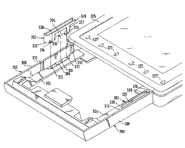
Fig. 1 and 2 i!lustrate schematically an upper shell 325 of the housing provi-
ded with an aperture 20û or display window which, in the ernbodiment, is
provided with a transparent pane 202. The width of the window transverse to
the reciprocation direction of the slider is 120 mm. The slider comprises lon-
gitudinal ledges 300 extending in reciprocation direction and having an L-sha-
ped cross section. Sheet-supporting arms 304 of the ledges extend parallel to
the plane of the window 200. The inner ends of arms 304 are spaced by a
width such that sheets of minimum size, e.g. 118 mm, are still supported and
cannot fall through the open slider bottom. T he upstanding arms 308 of the
ledges define the space necessary to accomodate sheets of a maximùm width
indicated to be 135 mm. Fig. 2 shows that even a sheet or photo print having
a width of 127.5 mm fully fills the display window although is is somewhat
misaligned when abutting ona of the upstanding arms 308. In F~igO 1 S the sliderledges ara shown equipped with stop rnembers 302 so as to reduce the width
between the arms 308 to about 127.5 mm, and as can be sean in Fig~ 1, even
a sheat of t23.75 mm width fully fills the display window when abutting one
of the stop members 302. Accordingly, the slider may be adapted to hold
shee~s having a width tolerance between 123.75 and 135 mm.
The illustrated embodiment is a sheet exchanger. That is, upon withdrawal of
the slider loaded with a stack of sheets, the lowermost sheet is retained in
2, ~
the housing, and when the slider is pushed back into the housing, this retained
sheet is placed on top of the stack. Thus, upon each reciprocation cycle of
the slider, the one retained sheet is displaced relative to the slider, and if the
slider is provided with the stop members 302, these must not interfere with
the exchange function. For this reason they are designed in a particular
manner to be described heteinafter.
Each supporting arm 304 of the slider ledges has a recess 306 having a con-
tour which is complementary to the contour of the allocated stop membar
302. This prevents the one sheet which is displaced relative to the slider from
creeping between the stop member and the sheet-supporting arm. Similarly,
guide extensions 310 are integrally molded with the guide arms 308 so as to
shield the gap between stop member 302 and arm 308~
The supporting arms 304 each have three asymmetrically arranged aperturas
within the confines of the recess 306. The two apertures marked 312 receive
anchoring hooks 314 integrally formed with the stop members. ~he third
aperture 316 receives a support foot 318 which stabilizes the position of the
stop member and further prevents interchanqing of the stop members upon
their being inserted; this is necessaty because the stop members themselves
are asymmetric, too.
Each stop member has a front ramp 320 and a rear ramp 322 so as to direct
a sheet corner inwards during exchange or filling the slider with a stack of
sheets. For the same reason, a fin~er recess 324 is delimited by similar
ramps. This recess permits to remove the stop member by withdrawing it
upwards.
R ibs 327 are integrally formed with the upper housing shell 325. One of these
ribs, marked 327', is so positioned that it would interfere with the stop
member unless the latter would be provided with a groove 326. These ribs
serve the purpose to bend downward the end of the one sheet which was re-
tained in the housing during the slider's return stroke so that this sheet end
O ~ ~
cannot enter between the upstanding arm 308 of the slider ledges and the
inner face of the housing. Of course, such sheet end must not enter between
the upper face of the stop member 302 and the housing either. For this re-
ason, the inner end of the stop member has guide slopes 328 which direct an
abutting sheet corner towards inner ramp 322, and the groove bottom end has
a chamfer 330 for the same reason.
:
- : ' ' :