Note: Descriptions are shown in the official language in which they were submitted.
`` X-8058
~5~
INSULATED DRUG SUPPLY POUC~
(1) Field of the Invention
The present invention relates tO belt-mounted supply pouches.
5 More specifically, the present invelltion relates to an environmentally
protected, belt-mounted supply poucll u~sed for holding drug cartridges
in a ~emperature insulated and contamillation resistant environment.
(2) Prior Art
Medical personnel al-e sollle~ les reqllired to administer
subcutaneous injections to patients in the field or outside the confines
of a medically sterile and tempera~ule controlled clinical enYironment.
Veterinarians are often called up()ll to administer injectic7ns to domestic
Iivestock in barnyards, corrals, or ou~-buil(lings. These environrnents
15 are typically subject to high levels of slut`ace and airborne
contaminants such as dirt~ anilllal e~cremenl, animal hair, feed
particulate or other forms of con[ami~ ioll~ In addition, these
environments are subject to weatller all(l temperature extremes. Field
injections typically take place yeal-rolllld in many geographical areas;
20 thus, the field environmenl in wllicll these injections occur is subject to
- the extreme cold of the winter months or northern latitudes and the
extreme heat of summer months or solltllern latitudes.
The need for a drug injection system for use in the field is
increasingly more important. In general, such systems employ a
2s deliYery means for injecting a drllg formlllation trom a prefilled and
disposable cartridge or contaillen Mally dl`LI_ formulations such as
antibiotics, steroids. vitamills~ or forllllllatiolls for increasing milk or
meat yield in dome:;tic alliMals can be a(lministered using these drug
delivery systems. One parliclllarly sigllificanl formula~ion is bovine
30 sornatotropin (BST) for use as all ~ngellt for increasing milk production
efficiency of dairy cows Often these formulations are sensitive to
-
x-805 8
temperature exlremes present in Ihe ellvironment in whic}~
adminis~ered. This is true not only because the formulations
themselves may be rendele(l inetlective beyond some temperature
threshold, but also becallse an increase in the viscosity of a particular
5 formulation associated with a decrease in temperature may render the
drug delivery system used with the formulation inoperable. An
important component klcking in a Iypical field-use drug delivery system
is a means tor storing a sllpply of dl u, contaillers in an insulated,
contamination resist,lnt and re,ldily port.lble sllpply pouch.
lo Prior art supply pOUCll design~ typically do not provide an
insulated cavity; since, most priol all pouclles are not oriented toward
medical or drug cartridge contaillment applications. Those prior ar~
pouches including inslllcltioll ale not designed to be attached to a belt
and worn on the waist ot` the llSCI~ 'I he ad(le(l benefit of a
15 contamination resistalll desigl~ not app.llellt in the prior art. Further,
the ability to reach into a covered pouch withollt opening a cover is not
apparent in the prior art The combinatioll s)t` these features has been
particularly difficult to achieve becallse of the bulky nature of the
insulating material and the need l`or a belt-mounted device to be small,
20 compact, and easily portable.
Thus, a readily portable yel telnperat~lre insulated and
contamination resistant ~llpply poucll ~c)r holding a supply of drug
cartridges or containers is needed.
x-sos8
SUMMARY OF'rH INVENTION
The preferred embodiment of the present invention includes a
belt-worn medical supply pouch ~Ised for holding a supply of drug
containers in a cavity in~ulated from contaminants and temperature
S extremes. The medical sllpply pouch comprises a substantially
rectangular housing fabricated from a thick insulating rmaterial and
covered with a water-prool' fabric. 'I'he sllpply pouch housing
comprises a front and back panel~ two si(te panels, a bottom and an
open top. The bottom, ~iicle, t'rOIll clllCI bacl~ panels are affixed at edges,
10 thus defining a housing with an inteliol regioll or cavity of the pouch.
Extending across the top openino l`rom one side panel to the other side
panel is a protective panel angle(l dowllwilld toward the interior cavity
of the pouch. The protective pallel restrict.s the entry of contaminants
into the interior ol' the poucll wllile allowillg a user of the pouch to
5 conveniently and repeilte(lly insel~ a hall(l into the pouch to retrieve a
drug cartridge contained theleill. Two bel~ loop members are affixed
to the back panel of the pouch. A llsel ol' the pouch may wear the
pouch on his/her hip by passillg a hclt thl-o~lgh the two belt members
affixed to the pouch, thus att(lcllill~~ the device to the waist of an
20 individual using the s~lpply poucll. A rectallglllar allxiliary pocket
affixed on three sides to the fron~ pallel of the pouch housing is
included with a closure flap exlen~ acrosci alld over the open top of
the auxiliary pocket. The sllpply poucll t'llrlller includes a small heating
element containment pocket at'fixe(l to an interior wall inside the cavity
~s of the pouch. The contailllllellt pocket is llse(l for holding a chemical
or electrical heating elelllelll io r l~e;l(illg Ihe interior cavity of the
supply pouch. The insllliltillg malerial ~ormillg the panels of the
medical supply pouch are covere(l ~dtll a watel proof nylon or other
material designed to be reSicitilnt to moistllre an(l contaminants.
x-8058
BRIEF DESCR51' r10N OF THE DRAWINGS
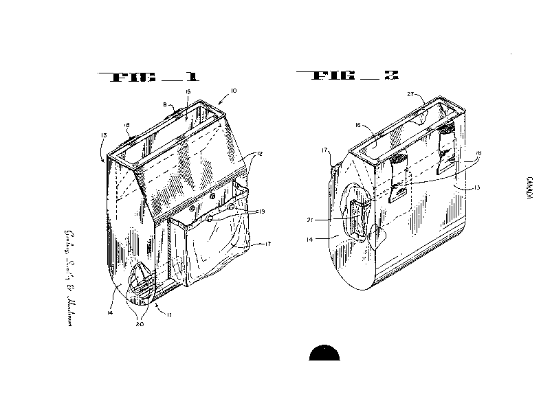
Figure I is a fronlcll eleva~ioll view of the medical supply pouch
of the present invention sllowillg the frollt panel, the top and a side
s panel.
Figure 2 is a real elevation vic~w ol` Ihe supply pouch showing
the back panel, the top and a si(3e panel.
Figure3isasectiollview sllowillg ~he internal cavity of the
pouch from a side view.
Figure 4 is a perspective, schematic view showing
an alternate embodiment of a portion of the medical
supply pouch of the present invention.
,: :
X-8058
DETAILED DESCRlP'l'lON Ol' THE PREFERRED EMBODIMENT
In the preferred embodimenls, described and illustrated in the
drawings provided herein, the presel1t invention disclosed provides a
5 readily portable means for hoklil1g a sllpply of drug containers in a
temperature-stable and contamil1cltioll re.~i.stant environment.
Referring to Fi~ure l, a pret`el-le(l embodiment of the supply :~
pouch l0 of the presen~ in\~el1tiol1 is illustrated. The medical supply
pouch 10 is shown to compri~ie a gel1elcllly rectangular housing formed :~
l0 from a front panel 12 and a back panel l 3 connected by or bonded
with side panels 14 and bottom 11 racl. of the panels comprising said
housing are formed from al1 in.~lllatil1g malerial approximately 1/2 inch
thick and Cllt at subslantially pel-pcl1liiclllal ed~es. The insulating
material is a commonly available syl1ll1elic t`oam or styrofoam material
5 with an insulating t`actor .suilclble ~or olltdoor llse,
In a first alternative embodimcl1~, lhe front panel l2, bottom 11
and back panel 13 are all forl11ed frol11 a sil1gle piece of insulating
material. In this embo(limenl~ a gel1crally rectal1gular piece of
insulating Malerial i~.:CUI .n1(l tol(le(l to torm a U-shaped front and back
20 panel with a rounde(l bottom. Side panels 14 are two additional pieces
of insulating material Clll IO COllt'Orlll tO the U-shaped edges defined by
the bottom, fronl and back panels. 'l'he ~ide panels 14 are connected
or glued to the edges of lhe boltom, frol1t and back panels with a
suitable and commonly available a(lhe~ive capable of bonding synthetic
25 foam or rubber material and re~ilient to nloislllre and temperature
extremes. In an alterl1a~ c embodimenl, ~ide panels 14 may be
connected to the botton1~ l`rol1t all(l h~lck panels by sewing the edges of
side panels 14 to front panel 12, bacl~ pal1el l~ and bottom l1. In
either equivalent manl1el, .~ide pal1el.~i 14 ale permanently connected to
3~ front panel 12, back panel l~ alld hollolll 11 lo form the housing of the
present invention.
()
,
,
x-8058
In a second alternative emt)odin~en~ front panel 12
13 and bottom 11 mcly be cu~ as three xeparate pieces of insulating
material instead of the single piece as described in the first alternative
embodiment. These three ~sllbstalltially rectangular pieces are cut from
S a stock of insulating matelicll alld bonded 01' connec~ed at the edges
along with side panels 14 tO fOIIll a sub~stal1tially rectangular housing
equivalen~ to the housil1g de.sclibed il) the lilst alternative embodiment.
In both the first and se~ol~d al~eln;llive cn1bodill1ents panels may be
connected at the edges ll~iing a .~llilable adlle~sive compound or by
0 sewing the edges together as dc.sclibed above.
In a third alterl1ative eml odil11el1l~ the housing 10 depicted in
Figure I is formed from l sil~gle mol(led piece of insulating material In
this equivalent embodimel~t the p anels l`orl11ing the housing of the
supply pouch ale forllle(l Iroll~ a ~ aly col1~stlllction Molding process
wherein each of tlle pal1els col11l~risil~ ~ lhc holl~sing are integrally
connected at edges in a ~single n1al1llfactlllil1g process. Techniques for
creating a unitary constr~lction hou.~ ot this ~ype are well known in
the art.
Using any of the ll1ree eglliv.llcl~l al~elr1ative embodiments
described abQve l ~enel llly re~a.ll) ~ r housil1g open at one end and
having a bottomj an ~lpri~ht frol1l and back panel~ and two side panels
is described. The housing thlls desclibed defines an opening 15 and an
internal cavity 25 ~l~sed l`ol sloliln~ lpply nf dlllg car~ridges. In order
to reduce the dimension Or apell~lr( IS a portion of front panel 12 is
angularly inclined or ~apelc(l lo~vald rear p.lnel 13. One edge of side
panels 14 is tapered in corlc.spon(lil~ rasl1ioIl with the incline of front
panel 1~ in order to acl1ieve closllle ol IhC hOll.Sillg without
overextended sides. The reduced opening I S is less vulnerable to
contamination entering the pOllCIl Irolll the top.
In a fourth alternalive en1bodil11el1l~ Irol1t panel 12 back panel 13
and side panel~s 14 are forl1le(1 Irol11 a single rectclngular piece of
t~
" ~058
insulating material 31 in Figure 4 that is rolled into a cylindrical shape
open at both snds. A bottom panel 33 may then be connected to the
edges of one end of the cylindrical shape to forrn a housing open at one
end wi~h a side panel and a bottom panel.
Referring again to Figures 1 and 3, top opening i5 is forrned
widely enough to allow access for the hand of a user of the supply
pouch. Opening 15 is also long enough to allow the removal of a drug
cartridge 20 contained within the cavity 25 of the housin~ 10. In order to
prevent foreign material or contamination from entering opening 15 and
e dropping into cavity 25 inside the housing, a protecthJe panel 16 is
provided as shown in Figures 2 and 3. Protective panel 16 is also a
substantially rectangular piece of insulating mat0rial positioned inside
opening 15 and connected to the interior surface of front panel 12. A
well-known adhesive or bonding agent is used to connect an upper
edge of protective panel 16 to the interior surface of front panel 12.
Protective panel 1~ is angied downward into the housing cavity and
inclined toward the interior surface of back panel 13. The incline or
tapering of the portion of front panel 12 which reduces the size of
opening 15 also serves to reduce the size of protective panel 16
necessary to protect opening 15. Proteetive panel 16 is typically not
bonded to the interior surface of back panel 13. Rather, one or more
edges of protective panel 16 flexibly abut or nearly abut back panel 13.
Protective panel 16 may also be connected to the interior surfaces of
side panels 14 at 35.
By virtue of the natural elasticity and flexibility of the insulating
material from which protective panel 16 and the other housing panels
are made, a user of the pouch will flexibly deflect protective panel 16
away from the interior of ~ack panel 13 when inserting hisfher hand
x-8058
into opening 15 and down into hou~ g c;lvity 25. When the user
removes his/her hand from hollsillg cavity 25, the natural elastic action
of the insula~ill;, maleri~ll ilg~ a.~ lO llrge the rehlrn of protective
panel 16 to a stable pOSili()ll in colll;l~l wilh or ~lbuttillg the interior
s surface of back panel 13 as showll h~ l'ig~ll-e 3, The incline of the
portion of front panel 12 whicll recillces ~he size of opening 15 also
minimizes the degree of det'lectioll l~ece~sal-y t'or ,protective panel 16
while the cavity 25 is beillo ~Iccc~se~l. Minimizing the degree of
deflection of the proteclivc pallcl 1( icnd~i lo increase the number of
o times the protective pallel 16 C.Ul l~c del'lccted before the elastic nature
of the material wears out,
There is no need for ally hillgt or spling Inaded mechanisms in
the preferred embodimelll ol' the plc.~iellt invelltion. Thus, the action of
retrieving a cartlidge froln Ihc pnucl~ C.lll he performed in one fluid
5 motion withoul the nee(l ~o m;lnil~ e a covel flap or opening
mechanism, The protective p;lllcl I( ;ll~ay~ covers opening 15 except
when a hand or other object is in Ihe process of accessing the interior
cavity 25, Thus, the prolective panc! 16 provides a maximum of
protection from conlclrnil~alioll w ilh ;l ll~illilll~llll of user maniplJlation.
20 The lack of user m~ulip~llalioll rc(llli,c(l lo access the pouch facilitates
the quick retrieval ol` dlll' callli(lgcs~ Ihelcl~y increasing the number of
injections that can be adlllillislcl~(l h~ a giVCIl time period.
In a first altemative embn(lilllclll~ the entire outer surfaces of the
housing and protective panel 16 alc c(lvelc(l witll a nylon pack cloth
2s material with a watel-pl()()l' ulelllan~ c().lting. Tlle nylon coating acts
to protect the pouch fr()lll IllOiS~IIC an(l colllalllill~ltion and to provide
an additional level of inslll.llion fOI Ille dlllg containers 20 contained
within cavity 25. Other e~l~livalclll walel-ploof and wear-resistent
coating materials may also be llse(l, SllCIl .IS a treated canvas or
30 suitable synthetic materi;ll, ~'hc illlCIi()l sllll'ace of the panels formingthe housing are also liue(l ~vilh a \v:llel-l)lool' nyloll matericll. As
.,
x-80s8
shown in Fi~ure 3 ~his intel'iOI' lillill" 26 exlends throughout the
surfaces forming cavity 2~5 al1(1 con~lects with the material covering the
upper surf lce ot` proleclive p Incl 1 ( L ~Icllding entirely around
opening 15 at the top ol` the housillg lO the exterior protective layer is
s connected to the interior Iining at a ~eaM ~7 extending around the
opening IS The seam 27 thus conl1ec~ the interior and exterior
protective layers is forl11ed llsing a sland.ll(l and well l<nown sewn
seam with piping added lor a beller ~eall1cr proof seal
In a seconcl altellliltive el11l~odill1el1l~ ~he hollsing does not
0 require a weather prool exleliol Ol i~ riOI protective layer Rather
the insulating materi.ll con~pli~il1 p;llleli ol` the pouch is itself a
water-proof ancl weal-resis~.ln~ m a~elial~ 1`hese insulating materials
such as a syn~hetic toal11 Ol stylol();ll11 n~aleri.ll may not require a
water-proof exterior layel~
lS The present invel1tiol1 is dcsi l~e(l lo be wol~ on a waist belt of a
user of the supply pouch In or~lel ~o provide this means of convenient
use and portability attaching means or belt loops 18 are provided as
shown in Figures 2 al1(1~ rhi.i a~laclling n1elns 18 comprises two
rectangular strips of nylol1 m.llc r ial alti~ed lo the exterior side of back
panel 13 Belt loops 1~ alc a~ l1e~1 IO l~a~l~ panel 13 at the upper and
lower edges of the S~lipS only l`his pl()\~i(les an opening between the
interior side of the belt loop al1d IhC e~lcl iol` side of back panel 13
through which a belt or s~lap m ay l~c slide.lbly inserted Belt loops 18
may be attached to bacl~ p.ll1el I ~ l11c uppel and lower point using a
sewn down stitch or a s~ clble a(lhe~ivc bonding agent~ The material
from which belt loops I ~ ale n1 Ide al1(1 Ihe ~echnique used to amx belt
loops 18 to baclc panel 1~ n1~ pro(lllce lclt loops of sufficient strength
to support a fully loa(led sllpply pollcll as i~ hangs from the belt of a
u ser
Referring to F`igllles I an(l a sl11.l11 p()cket 21 is attlched to the
interior wall of frollt p.ll1el 1 ? all(l col1~ail1e(1 within cavity 25 Pocket
1(~
x-80s8 ;~ $~
21 is used for holding a small he.~ g element, such as a chemically
active or bat~ery operaled heater l`or lhe pulpose of heating the interior
cavity 25 of housing I(). In Ihe prcl`erlc(l embodiment, pocket 21 is
forrned from a substantially recl.lng~llar piece of nylol1 or other suitable
material sewn or glued arolllld thlce !iides to the interior lining of front
panel 12. Three sides ol` Ihe rcclan~ ll pocket thus attached leaves
the top side open and accessible l`or inseltil1g a ~small heating element
into the pocliel. Me~ho(ls lor ~iCWil~" Ol` ~ ;, pocket 21 tO the interior
lining in this manllel ale well kno~ e .Irl
0 1n an alterna~ive embodiment, heatillg containment means 21
may be implemented as ~I holizoll~ll loop ol` m~lterial attached to the
interior lining of from p.lnel 12. I ~vo cl~ds of lhe loop are attached
leaving the sulfclce bet~een lhc el~ds o pCIl all(l accessible for slideably
placing a heatillg elemenl ~l1eleilu 11~ Ihis en~bo(liment, the heating
IS element must be configllle(l il~ .a \~ay IO plevellt the heating element
from sliding all the way thl`O~Igll thc COI~t;lilllllellt loop.
Whether the he~ltil1g elcmclll ~ol1l~linlllent meclns is implemented
as pocket 21, a hori~.onlal loop. Or olhcl me.llls~ the heating element
containment means plovides ~l1c desinll~lc l`ealllles of holding a heating
2() element up al-(l away Irol1l dlll~ ~alllid~c~ 20 while still providing easy
access for a usel ~o insell ~I h.ll1(1 inlo opcl~ IS down into cavity 25
in order to retrieve one ol` lhe dlllg c.lrlli(l;ges 20. Also, by inserting a
hand into opening IS .Ind illtO C.l\'ily 2~ I he~lling element may be
installed into pocl~et 21 Or rel1lo~c(1 thclel`lolll as necessary.
Referring ag ail1 to I- iglllC~ d ~ exterllal allxiliary pocket
17 is affixed to the olltsi(lc s~ c ol Ironl pallel 12. In order to
provide a s~orage meal1s l`or ilCl11~ rc(lllilillg lhe insulated and
contamination resistant envirol11nel1l insi(le lhe housing, auxiliary
pocket 17 is provided In tlle prctellc(l eml odilllent~ pocket 17 is
fabricated from a sllbslallti.llly rccl;lll~lll.ll piece of nylon or other
suitable material stllrdy enollgl1 to \~dtll.~ l lhe more severe
11
x-sos8
environmental conditioll~ ollt~idc Ihc l~o~lch. poci~et 17 is sewn or
glued around ~hree sides ollto tlle o~lt~ide slllt`ace of front panel 12. A
pocket thus attached ptovi(le.~ .Ul Ope~ t the top for access to items
stored therein. A pair of watel-lesistallt snaps 19 are attached to the
open edge of pocket 19 ill ordel to plovide clos-lre of the pocket
against snap receiving all~l loclihlg meal~ att.lclled to the outer surface
of front panel 12. Snapping mealls (i.e. sllap buttons) and a method for
attaching same to poci~et 17 alld l`ront pallel 12 are well known in the
art.
0 Thus, a belt worn medical sllpply pollch used for holding a
supply of drug cont~ lers il) Ll C~l~'ily iu~lllate(l from contaminants and
temperature extrellles is dis~lo~;-d.
Althollgll thi~ illvcnlioll h;~ hc.~ h()~vn in relation to particular
embodiments, it shoul(l n()l bc coll~;i-lclcd so limited. Rather, it is
S limited only by the appende(l clailll~.