Note: Descriptions are shown in the official language in which they were submitted.
- 2 - 205023 1
A GRID CEILING
The present invention relates to grid ceilings. Many different forms of
grid ceilings have been proposed, these usually being designed to cover up
services such as water and gas feed pipes, electric wiring, air conditioning andthe like. For example U.S. Patents Nos. 4,658,562 and 4,665,674 show one
particular form of ceiling, in which a main grid is provided and into each of the
rectangular openings in this grid is fitted a grid panel. A somewhat different
structure is shown in U.S. Patent No. 4,625,470 in which each grid panel is, in
effect, formed by two T-shaped members, the stem and the arms of which are
hinged to one another. These grid ceilings are generally satisfactory, but give
a rather limited visual effect. It is an object of the present invention to provide
the facility for giving a greater variety of visual effect.
It is now proposed, according to the present invention, for the grid ceiling
to comprise a plurality of elongate first support members, said first support
members having parallel longitudinal axes; a plurality of elongate second support
members, said second support members having parallel longitudinal axes angled
with respect to the longit~1flin~l axes of the first support members, effective to
define therewith a grid with polygonal first openings therein; a first grid element
inserted in at least one of said first openings, said first grid element defining
therein at least one second opening and a second, smaller grid element inserted
in said at least one opening of said first grid element.
With such a structure one can readily modify the format of the second
smaller grid element which can be inserted in all or in some of the second
openings in a variety of different arrangements to give a totally different visual
effect.
Preferably the first grid element comprises a plurality of first elongate
members angled with respect to one another effective to define said at least onesecond opening, whereby said at least one second opening is of polygonal shape.
The second grid element may comprise a plurality of second elongate grid
members angled with respect to one another, the second grid members being
2050~231
- 3
shorter in length than the relevant parallelly extending first grid members. In
this way one can have progressively smaller grid elements.
Desirably the first grid members are mounted at a level different from the
level of the first and second support members and alternative or additional, thesecond grid members are mounted at a level different from the first and second
support members.
Advantageously a third opening is defined in the or each second grid
element and a third grid element is mounted in the third opening. Additional
grid elements can continue to be mounted in this way. If the grid elements are
mounted at different levels, as suggested above, one can produce, in effect, a
pyramidal shape in each opening in the support members.
In order that the present invention may more readily be understood, the
following description is given, merely by way of example, reference being made
to accompanying drawings in which:
Figure 1 is a perspective view showing a portion of one embodiment of
grid ceiling according to the invention;
Figure 2 shows, in perspective, first and second grid elements of the
ceiling of Figure 1, prior to being assembled; and
Figure 3 is a view similar to Figure 1, but showing a larger portion of a
second embodiment of grid ceiling according to the invention.
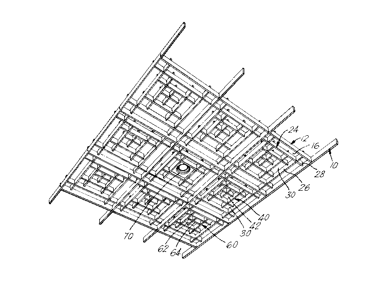
Referring first to Figure 1, there is illustrated therein a presently preferred
embodiment of grid ceiling according to the invention. This comprises a support
grid comprising a plurality of elongate first support members 10, having
longitudinal parallel axes 11 and a variety of elongate second support members
12, the second support members having parallel longitudinal axes 13 angled in
the embodiment illustrated at right angles to the axes 11 effective to define
therewith the grid with polygonal in this instance, rectangular first openings 16
therein.
The support members 10, 12 in this construction are each in the form of
U-profiled sheet metal members having a lower web 18, side flanges 20 these
having inturned rims 22 at their upper edges.
~4~ 205023 1
Mounted within some, or all, of the openings 16 are first grid elements
24 which are each formed of a plurality of first elongate members 26 (Figure 2)
and second elongate grid members 28, defining a central second opening 30.
The grid members 26, 28 are again each of U-profiled sheet metal, similar to thesupport members 10, 12 and they may be formed of the same cross section
material or, as shown, of smaller cross section material. The grid members 26
each have intermediate their ends cutouts extending upwardly from the web
portion of the grid member 26 to about half the height of the grid member 26
while the second grid members 28 have similar, complementary cutouts whereby
the members 26, 28 can be interfitted, as shown in the drawings, to define end
portions 31, 32 which are notched at 34, 36. The distance between the ends of
the grid members 26, defined by the notches 34 at the ends thereof, is chosen tobe a close fit between the side walls or flanges 20 of the support members 12 sothat the unnotched portions 35 thereof rest on the rims 22 and prevent the grid
moving in that direction.
Similarly the lengths of the grid members 28 between the notched portions
36, at the ends thereof, is adapted to the spacing between the support members
10 so that the unnotched portions 37 of grid members 28 rests on the rims of thesupport members 10.
In a similar way, second grid elements 40, are identical, but of smaller
dimensions, are mounted in the openings 30 and define a third opening 42 in
which a third grid element 44, again of identical but smaller construction is
mounted. This again defines a further central opening 46 in which a further gridelement 48 is mounted.
In the embodiment shown, because of the provision of the notches 36 in
each of the grid members, this notch extending approximately 2/3rds of the way
up the length of the associated grid member, each grid element is mounted higherthan the support grid, the second grid element is mounted higher than the first
grid element and so on. In this way a generally pyramidal structure can be
provided.
205023 1
For internal use, the grid elements may simply be retained in place by
gravity. For external use, where the assembly may be subjected to winds and
other environmental problems, it may be advantageous for the grid elements to
have means positively to retain them in place and for this reason there is
illustrated in Figure 2 a rounded protrusion 50 on the end of each notched end
portion 34, 36 and this being adapted to be engaged in a corresponding opening
in the adjacent support member 10, 12. Second and subsequent grid elements
may be retained by similar protrusions engaging in similar corresponding
openings 52 of a surrounding grid element.
In the second embodiment of ceiling shown in Figure 3, like parts have
been indicated by like reference numerals. As before, there are a plurality of
elongate first support members 10 and elongate second support members 12
defining rectangular first openings 16 therein. Mounted within these openings
16 are first grid elements 24 which are each formed of a plurality of first
elongate grid members 26 and second elongate grid members 28, in a similar
manner to that described above. The second grid elements again define a second
central opening 30 in which is mounted, in a similar way, second grid elements
40 which are identical, but of smaller dimensions with the first grid elements 24
and define a third opening 42.
At this point, however, there is a variation as compared with that of the
first embodiment. In the third opening 42 is mounted a different form of third
grid element 60. In this construction the third grid element 60 consists of a
cross-shaped member defined by a first elongate element 62 and a second
elongate element 64. It will be seen that this gives rather a different visual
effect.
At the centre of the grid shown in Figure 3 there is mounted a further
possible "third element", namely, a light fitting 70. It will be appreciated that
in a given ceiling several such light fittings could be mounted at appropriate
locations.
.
- 6 - 2050231
The structure of the present invention is therefore very well adapted to
significant variations to suit the requirements of a particular ceiling designerdesiring to give a particular visual and/or lighting effect.